
Service Manual


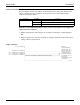


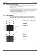


Table Of Contents
- Cover
- Table of contents
- Part 1 List of Functions
- Part 2 Specifications
- Part 3 Printed Circuit Board Connector Wiring Diagram
- Part 4 Refrigerant Circuit
- Part 5 Functions and Control
- Part 6 Test Operation and Field Settings
- Part 7 Remote Controller
- Part 8 Troubleshooting
- 1. Troubleshooting with LED
- 2. Service Diagnosis
- 3. Error Codes and Description
- 4. Troubleshooting for CTXG, CTXS, FTXS, CDXS, FDXS, FVXS Series
- 5. Troubleshooting for FFQ Series
- 6. Troubleshooting for Branch Provider (BP) Unit
- 7. Troubleshooting for Outdoor Unit
- 8. Thermistor Resistance/Temperature Characteristics
- 9. Pressure Sensor
- 10. Method of Replacing Inverter’s Power Transistors Modules
- Part 9 Appendix

Field Settings SiUS181631EA
138 Test Operation and Field Settings
2.1.6 Setting of Vacuuming Mode
In order to perform vacuuming operation at site, fully open the expansion valves of indoor and
outdoor units and turn on some solenoid valves.
Operating procedure
(1) In setting mode 2 with units in stop mode, set the item No.21 (refrigerant recovery/vacuuming
mode) to ON. The respective expansion valve of indoor and outdoor units are fully opened. Test
Operation and Under Centralized Control are displayed on the remote controller, and the
indoor/outdoor unit operation is prohibited.
After setting, do not cancel setting mode 2 until completion of Vacuuming operation.
(2) Use the vacuum pump to perform vacuuming operation.
(3) Press MODE (BS1) button once and reset setting mode 2.
2.1.7 Check Operation
To prevent any trouble in the period of installation at site, the system is provided with a test
operation mode enabling check for incorrect wiring, stop valve left in closed, coming out (or
misplacing with suction pipe thermistor) or discharge pipe thermistor and judgment of piping length,
refrigerant overcharging, and learning for the minimum opening degree of electronic expansion valve.
Unit stopping
Press the TEST button for 5 seconds.
10 seconds to 10 minutes
LED display (H1P~H7P) (
k :ON h :OFF l :BLINK)
hhkhhhh
hlhhhhk
Pressure equalizing
Step 1
20 seconds to 2 minutes
10 minutes
3 minutes
15 minutes
hlhhhkh
Cooling start controlStep 2
hlhhhkk
hlhhkkk
Stability waiting operationStep 3
Refrigerant overcharge judgment
Step 7
• Stop valve close check
• Wrong wiring check
• Piping length check
hlhhkhh
hlhhkhk
hlhhkkh
Judgment function
Step 4~6
5 seconds
hlhkhhk
hlhkhkh
Pump-down residual operation
Step 8
2 minutes
Standby for restarting
Completion
Step 9
(R12957)