
Service Manual


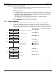


Table Of Contents
- Cover
- Table of contents
- Part 1 List of Functions
- Part 2 Specifications
- Part 3 Printed Circuit Board Connector Wiring Diagram
- Part 4 Refrigerant Circuit
- Part 5 Functions and Control
- Part 6 Test Operation and Field Settings
- Part 7 Remote Controller
- Part 8 Troubleshooting
- 1. Troubleshooting with LED
- 2. Service Diagnosis
- 3. Error Codes and Description
- 4. Troubleshooting for CTXG, CTXS, FTXS, CDXS, FDXS, FVXS Series
- 5. Troubleshooting for FFQ Series
- 6. Troubleshooting for Branch Provider (BP) Unit
- 7. Troubleshooting for Outdoor Unit
- 8. Thermistor Resistance/Temperature Characteristics
- 9. Pressure Sensor
- 10. Method of Replacing Inverter’s Power Transistors Modules
- Part 9 Appendix

Field Settings SiUS181631EA
132 Test Operation and Field Settings
Switching Mode (1):
Set Cool/Heat Separately for Each Outdoor Unit System by Indoor Unit Remote Controller
It does not matter whether or not there is outdoor - outdoor unit wiring.
Set the DIP switch DS1-1 of the outdoor unit PCB (A2P) to IN (factory setting).
Set cool/heat switching to IND (individual) in the setting mode 1 (factory setting). (Refer to page
126 for details.)
Switching Mode (2):
Set Cool/Heat Separately for Each Outdoor Unit System by Cool/Heat Selector
Connect the cool/heat selector (option) to the terminals A, B, C on the outdoor unit PCB (A4P).
It does not matter whether or not there is outdoor - outdoor unit wiring.
Set the DIP switch DS1-1 of the outdoor unit PCB (A2P) to OUT.
Set cool/heat switching to IND (individual) in the setting mode 1 (factory setting). (Refer to page
126 for details.)
Service PCB
(A2P)
Noise filter PCB
(A3P)
C/H selector PCB
(A4P)
Terminal strip
(Control) (X2M)
DIP switch
Switching mode (1)
DS1-1
Set the DIP switch
DS1-1 to IN.
DIP switch
Switching mode (2)
DS1-1
Set the DIP switch
DS1-1 to OUT.