
Service Manual
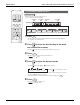
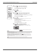

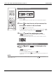


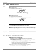
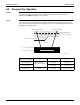
Table Of Contents
- Cover
- Table of contents
- Part 1 List of Functions
- Part 2 Specifications
- Part 3 Printed Circuit Board Connector Wiring Diagram
- Part 4 Refrigerant Circuit
- Part 5 Functions and Control
- Part 6 Test Operation and Field Settings
- Part 7 Remote Controller
- Part 8 Troubleshooting
- 1. Troubleshooting with LED
- 2. Service Diagnosis
- 3. Error Codes and Description
- 4. Troubleshooting for CTXG, CTXS, FTXS, CDXS, FDXS, FVXS Series
- 5. Troubleshooting for FFQ Series
- 6. Troubleshooting for Branch Provider (BP) Unit
- 7. Troubleshooting for Outdoor Unit
- 8. Thermistor Resistance/Temperature Characteristics
- 9. Pressure Sensor
- 10. Method of Replacing Inverter’s Power Transistors Modules
- Part 9 Appendix

FFQ Series Function SiUS181631EA
100 Functions and Control
8.4 Program Dry Operation
Outline Program dry operation removes humidity while preventing the room temperature from lowering.
Since the microcomputer controls both the temperature and airflow rate, the temperature
adjustment and FAN setting buttons are inoperable.
Details The microcomputer automatically sets the temperature and airflow rate. The difference between
the room thermistor temperature at start-up and the target temperature is divided into two zones.
Then, the unit operates in an appropriate capacity for each zone to maintain the temperature and
humidity at a comfortable level.
Room thermistor
temperature at start-up
Target temperature
X
Thermostat OFF point
Y
Thermostat ON point
Z
24.5°C or more
(76.1°F or more)
Room thermistor
temperature at start-up
X - 2.5°C
(X - 4.5°F)
X - 1.0°C
(X - 1.8°F)
16.5 ~ 24°C
(61.7 ~ 75.2°F)
X - 2.0°C
(X - 3.6°F)
X - 1.0°C
(X - 1.8°F)
16°C or less
(60.8°F or less)
16°C
(60.8°F)
X - 2.0°C
(X - 3.6°F)
X - 1.0°C = 15°C
(X - 1.8°F = 59°F)
Zone A = Thermostat OFF
Target temperature X
Zone B
Room temperature Room temperature
Zone C = Thermostat ON
Y = X – 2.5°C (4.5°F)
or
Y = X – 2.0°C (3.6°F)
Z = X – 1.0°C (1.8°F)
X – 1.0°C (1.8°F)
(R24367)