
Specifications


4P357732-1 – 2014.04 Page 38 of 58
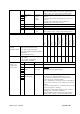
Holding register
VRV
Sky-air
HRV
Split
VRV hydrobox
LT & HT
Air curtains
ERQ control box
Heating
Applied
On/Off
On/Off of indoor units
* For VRV hydrobox LT & HT &
Heating:
On/off “space cooling/heating”
O
O
O
O
O*
O
O
O*
O
Fan speed (Air
flow rate)
LL, L, M, H, HH (depending on
indoor unit capability)
* Air curtain:
CYV models: not available CYQ
models: available
HRV (ventilation rate):
VAM models: available
VKM models: not available
O
O
O*
-
-
O*
-
-
-
Fan direction
Swing, Flap direction (depending on
indoor unit capability)
O
O
-
-
-
-
-
-
-
42001 (1-00)
42004 (1-01)
.. (step of 3)
42190 (4-15)
Bit
Description
Meaning
15
-
14
Fan speed
0 till 7
This value is depending on “fan speed steps
capability” value
Value
0
1
2
3
4
5
6
7
Fix
-
-
-
-
-
H
-
-
2step
-
L
-
-
-
H
-
-
3step
-
L
-
M
-
H
-
-
5step
-
LL
L
M
H
HH
-
-
(note: Fan control flag bit 7-6-5-4 must be set to
value 6)
Note: The BMS needs to copy input register value:
32001 (1-00)… bit 14-13-12 to this holding register.
(note: in case no fan capability this register should be
set to 0)
HRV (ventilation rate) : For VAM units:
Values 0/1/2:L & 3/4/5/6/7:H
(note for HRV: fan speed steps capability is fixed to
0)
(note for HRV: Fan control flag bits 7-6-5-4 are not
applicable)
(note for HRV: Related input register with actual
value: 32001 (1-00)… bit 14-13-12
Attention during the BMS copy: value 3 “L” of input
register should be translated to value 2 “L” in holding
register by the BMS to avoid a change to “H”
ventilation rate.
Value 7 “H” of input register can be copied to equal
value7 “H” in holding register.)
13
12
11
-
10
Fan direction
0 till 7
This value has only meaning if “Fan direction
capability” exist
0: P0, 1: P1, 2:P2, 3: P3, 4: P4, 5: -, 6: Stop, 7: swing
P0 = horizontal direction
P4 = vertical direction
9
8