
Specifications


4P357732-1 – 2014.04 Page 33 of 58
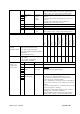
Input register
VRV
Sky-air
HRV
Split
VRV hydrobox
LT & HT
Air curtains
ERQ control box
Heating
Applied
Room
temperature
Suction temperature of indoor units
(or user interface sensor
temperature)
* Split: KRP928BB2S is required
O
O
-
O*
O
-
O
O
-
32005 (1-00)
32011 (1-01)
.. (step of 6)
32383 (4-15)
Bit
Description
Meaning
15..0
Room
temperature
- 511,9 ..
511,9°C
(unity: 0,1°C)
16 bit signed integer equals the value multiplied by
10
(bit 15= sign)
Additional notes concerning the room temperature Or Suction temperature.
By default the Suction temperature value is applicable.
If the room temperature of the user interface (e.g. BRC1E52A/B7 or BRC2/3E52C7) is required, following
settings should be confirmed on the user interface:
Mode No. –
First Code
No.
( ) = group
setting
Description of setting
Required values:
User interface settings (e.g. BRC1E52A/B7 or BRC2/3E52C7)
1c – 1
Thermostat sensor used for the
"Auto" operation mode and the
Setback function (room temperature on detailed
display).
Value 02:
Remote controller
thermistor
Unit settings
10 (20) – 2
Thermostat sensor in the remote
controller
Value 03:
Use exclusively
10 (20) – 5
Sensor value information to DIII devices
Value 02:
Sensor value as
set by 10-2-0X or 10-6-0X.
10 (20) – 6
Thermostat sensor in group
control
Value 02:
Use both the unit sensor (or
remote sensor if installed) AND
the remote controller sensor.
For more information, refer to the installation manual of applicable indoor unit.