00_CV_3P249378-6L.fm Page 1 Sunday, September 30, 2012 5:07 PM INSTALLATION MANUAL English SPLIT SYSTEM Air Conditioners Deutsch MODELS (Ceiling Suspended type) FHQ35CAVEB FHQ50CAVEB FHQ60CAVEB FHQ71CAVEB FHQ100CAVEB FHQ125CAVEB FHQ140CAVEB Français Español Italiano CAREFULLY READ THESE INSTRUCTIONS BEFORE INSTALLATION. KEEP THIS MANUAL IN A HANDY PLACE FOR FUTURE REFERENCE. ÅëëçíéêÜ LESEN SIE DIESE HINWEISE VOR DER INSTALLATION SORGFÄLTIG DURCH.
01_EN_3P249378-6L.fm Page 1 Sunday, September 30, 2012 2:30 PM FHQ35CAVEB FHQ50CAVEB FHQ60CAVEB FHQ71CAVEB FHQ100CAVEB FHQ125CAVEB FHQ140CAVEB SPLIT SYSTEM Air Conditioners Installation manual CONTENTS 1. SAFETY PRECAUTIONS .................................................................................... 1 2. BEFORE INSTALLATION .................................................................................... 3 3. SELECTION OF INSTALLATION LOCATION ................................................
01_EN_3P249378-6L.fm Page 2 Sunday, September 30, 2012 2:30 PM • Be sure to use only the specified parts and accessories for installation work. Failure to use the specified parts may result in the air conditioner falling down, water leakage, electric shocks, a fire, etc. • Install the air conditioner on a foundation that can withstand its mass. Insufficient strength may result in the air conditioner falling down and causing injury.
01_EN_3P249378-6L.fm Page 3 Sunday, September 30, 2012 2:30 PM 2. BEFORE INSTALLATION When unpacking and moving the indoor unit after unpacked, do not apply force to the piping (refrigerant and drain) and resin parts. • Make sure to check in advance that the refrigerant to be used for installation work is R410A. (The air conditioner will not properly operate if a wrong refrigerant is used.) • For installation of the outdoor unit, refer to the installation manual attached to the outdoor unit.
01_EN_3P249378-6L.fm Page 4 Sunday, September 30, 2012 2:30 PM 2-2 OPTIONAL ACCESSORIES • For this indoor unit, the remote controller is separately required. • There are 2 kinds of remote controller; wired type and wireless type. Install the remote controller to the place where the customer has given consent. Refer to the catalog for the applicable model. (Refer to the installation manual attached to the remote controller for how to install.
01_EN_3P249378-6L.fm Page 5 Sunday, September 30, 2012 2:30 PM Points of the operation explanation In addition to the general usage, since the items in the operation manual with the WARNING and CAUTION marks are likely to result in human bodily injuries and property damages, it is necessary not only to explain these items to the customer but also to have the customer read them.
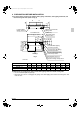
01_EN_3P249378-6L.fm Page 6 Sunday, September 30, 2012 2:30 PM 4. PREPARATION BEFORE INSTALLATION (1) For the locations of indoor unit hanging bolts, piping outlet holes, drain piping outlet hole, and electric wiring inlet hole. (Refer to Fig.
01_EN_3P249378-6L.fm Page 7 Sunday, September 30, 2012 2:30 PM (3) Remove the parts of the indoor unit. 1) Remove the suction grille. • Slide the suction grille fixing knobs (35, 50 type: 2 places for each, 60~140 type: 3 places for each) toward backward direction (as shown by an arrow) to open the suction grille widely. (Refer to Fig. 4) • Keeping the suction grille opened, hold the knob at the back of the suction grille and at the same time, pull the suction grille forward to remove. (Refer to Fig.
01_EN_3P249378-6L.fm Page 8 Sunday, September 30, 2012 2:30 PM CAUTION Do not remove the tape (milky white) applied to the outside of the indoor unit. It may cause electric shocks or a fire. (4) Install the hanging bolts. • Use M8 or M10 bolts for hanging the indoor unit. • Adjust the length of the hanging bolt from the ceiling in advance. (Refer to Fig.
01_EN_3P249378-6L.fm Page 9 Sunday, September 30, 2012 2:30 PM (4) Tighten the hanger installing bolts (M8) at 4 places securely. (Refer to Fig. 11) Attachement part Hanger Reinforcing plate (left/right) When carrying the indoor unit, do not hold the reinforcing plates. Hanger fixing screw (M5) Hanger installing bolt (M8) Fig. 11 (5) When hanging the indoor unit, make sure to use the level to have better drainage and install it horizontally.
01_EN_3P249378-6L.fm Page 10 Sunday, September 30, 2012 2:30 PM 6. REFRIGERANT PIPING WORK • For the outdoor unit refrigerant piping, refer to the installation manual attached to the outdoor unit. • Carry out insulation of both gas and liquid refrigerant piping securely. If not insulated, it may cause water leakage. For gas piping, use insulation material of which heat resistant temperature is not less than 120°C. For use under high humidity, strengthen the insulation material for refrigerant piping.
01_EN_3P249378-6L.fm Page 11 Sunday, September 30, 2012 2:30 PM • For the tightening torque, refer to the Table 1. Table 1 φ 6.4 15.7 ± 1.5 8.9 ± 0.2 φ 9.5 36.3 ± 3.6 13.0 ± 0.2 φ 12.7 54.9 ± 5.4 16.4 ± 0.2 φ 15.9 68.6 ± 6.8 19.5 ± 0.2 Flare shape 45˚±2˚ Dimension for processing flare A (mm) R0.4-0.8 A Tightening torque (N·m) 90˚±2˚ Piping size (mm) CAUTION • Do not have oil adhere to the screw fixing part of resin parts. If oil adheres, it may weaken the strength of screwed part.
01_EN_3P249378-6L.fm Page 12 Sunday, September 30, 2012 2:30 PM • After leak test, referring to Fig. 15, insulate both the gas and liquid piping connection with the attached joint insulating material (6) and (7) to prevent the piping from getting exposed. Then, tighten the both ends of insulating material with the clamp (4). • Wrap the sealing material (Small) (9) around the joint insulating material (6) (flare nut section), only the gas piping side.
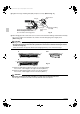
01_EN_3P249378-6L.fm Page 13 Sunday, September 30, 2012 2:30 PM (1) For rear side piping • Remove the rear piping penetration cover, and connect the piping. (Refer to Fig. 16 and Fig. 18) (2) For upward piping • For upward piping, L-shaped connection piping kit (optional accessory) will be required. • Remove the top panel penetration cover, and use the L-shaped connection piping kit (optional accessory) to conduct piping. (Refer to Fig. 16 and Fig.
01_EN_3P249378-6L.fm Page 14 Sunday, September 30, 2012 2:30 PM • After piping is finished, cut the removed penetration cover along the shape of piping, and install. Also, for top panel penetration cover, as it was before removed, put the horizontal blade motor and thermistor lead through the clamp of the top panel penetration cover and fix. (Refer to Fig. 16 and Fig.
01_EN_3P249378-6L.fm Page 15 Sunday, September 30, 2012 2:30 PM 7. DRAIN PIPING WORK (1) Carry out drain piping. • Carry out drain piping so that drainage can ensured. • Drain piping can be connected from the following directions: For right rear/right side, refer to Fig. 18 of ‘‘6. REFRIGERANT PIPING WORK’’, and for left rear/left side, refer to Fig. 21. • When conducting left rear/left side drain piping, remove the protection net.
01_EN_3P249378-6L.fm Page 16 Sunday, September 30, 2012 2:30 PM • Make sure to use the attached drain hose (1) and metal clamp (2). Also, insert the drain hose (1) into the root of the drain socket, and tighten the metal clamp (2) at the root of the drain socket tightly. (Refer to Fig. 25 and Fig. 26) (Install the metal clamp (2) so that the tightening part is in the range of about 45°as shown in the Fig. 26.) (Do not bond the drain socket and drain hose.
01_EN_3P249378-6L.fm Page 17 Sunday, September 30, 2012 2:30 PM 100mm or more < CAUTION > • To avoid the attached drain hose (1) getting excessive force, do not bend nor twist it. (It may cause water leakage.) • When conducting the centralized drain piping, follow the instructions in Fig. 28. For the diameter of the centralized drain piping, select the diameter matching the capacity of the indoor unit to be connected. (Refer to technical guidebook.
01_EN_3P249378-6L.fm Page 18 Sunday, September 30, 2012 2:30 PM 8. ELECTRIC WIRING WORK 8-1 GENERAL INSTRUCTIONS • Make certain that all electric wiring work is carried out by qualified personnel according to the applicable legislation and this installation manual, using a separate circuit. Insufficient capacity of the power supply circuit or improper electrical construction may lead to electric shocks or a fire. • Make sure to install an earth leakage breaker in accordance with applicable legislation.
01_EN_3P249378-6L.fm Page 19 Sunday, September 30, 2012 2:30 PM • If the above is not available, make sure to observe the following items. • 2 wirings of different sizes to the terminal block for power supply is prohibited. Connection of 2 wirings of same size must be carried out on both sides. Connection of 2 wirings on one side is prohibited. Connection of wirings of different sizes is prohibited. (Abnormal heating may occur if the wirings are not tightened securely.
01_EN_3P249378-6L.fm Page 20 Sunday, September 30, 2012 2:30 PM Outdoor unit Indoor unit Terminal block (X2M) Earth terminal R10 or more Terminal block Terminal block Terminal numbers of outdoor and indoor units must be matched R10 or more Transmission wiring and Earth wiring Transmission wiring connection method Forbidden • Do not carry out soldering finish. Transmission and earth wiring connection method Forbidden • Never connect the power supply wiring. • Do not carry out soldering finish.
01_EN_3P249378-6L.fm Page 21 Sunday, September 30, 2012 2:30 PM Remote controller wiring Wiring fixture (11) (accessory) Clamp (4) (accessory) (1) Install the fixture at the wiring entrance side. Power supply wiring and Earth wiring DETAIL (2) Fix the wiring to the fixture by clamps so that no tension will be given to the terminal connection. Clamp (4) (accessory) (3) To avoid the loosing of the power supply wiring and Earth wiring, band the clamp to tightly fit the fixture at terminal block side.
01_EN_3P249378-6L.fm Page 22 Sunday, September 30, 2012 2:30 PM • 2 remote controllers control: 2 remote controllers control 1 indoor unit. (Refer to Fig. 36) Simultaneous operation system Pair type Power supply 220 - 240V ~ 50Hz Earth leakage breaker Power supply 220 - 240V ~ 50Hz Earth leakage breaker Outdoor unit Outdoor unit 1 2 3 1 2 3 NOTE 1) NOTE 1) 1 2 3 1 2 3 1 2 3 P1 P2 P1 P2 Indoor unit Indoor unit (Master) Remote controller (Optional accessory) P1 P2 P1 P2 NOTE 2) Fig.
01_EN_3P249378-6L.fm Page 23 Sunday, September 30, 2012 2:30 PM When implementing group control • When using as a pair unit or as a master unit for simultaneous operation system, you may carry out simultaneous start/stop (group) control up to 16 units with the remote controller. (Refer to Fig. 34) • In this case, all the indoor units in the group will operate in accordance with the group control remote controller. • Select a remote controller which matches as many of the functions (airflow direction, etc.
01_EN_3P249378-6L.fm Page 24 Sunday, September 30, 2012 2:30 PM Control with 2 remote controllers control Power supply 220 - 240V ~ 50Hz Earth leakage breaker Indoor unit (Slave) Outdoor unit Outdoor unit 1 2 3 Indoor unit (Master) NOTE) 1 2 3 P1 P2 Indoor unit Remote controller P1 P2 (Optional accessory) P1 P2 Remote controller (Optional accessory) Remote Remote controller 1 controller 2 (Optional (Optional accessory) accessory) Fig.
01_EN_3P249378-6L.fm Page 25 Sunday, September 30, 2012 2:30 PM 10. MOUNTING SUCTION GRILLE · DECORATION SIDE PANEL Install securely in the reverse order when decoration side panel and suction grille were removed. • When installing the suction grille, hang the string of the suction grille to the hanging part of the indoor unit shown Fig. 38. CAUTION When closing the suction grille, the strap may get caught. Confirm that the strap does not stick out of the side of the suction grille before closing.
01_EN_3P249378-6L.fm Page 26 Sunday, September 30, 2012 2:30 PM 11-2 WHEN USING WIRELESS REMOTE CONTROLLER • When using a wireless remote controller, it is necessary to set the wireless remote controller address. Refer to the installation manual attached to the wireless remote controller. 11-3 SETTING CEILING HEIGHT (TYPE 100 OR LESS) • When installing indoor unit type 35 - 100, specify the SECOND CODE No. in accordance with the ceiling height.
01_EN_3P249378-6L.fm Page 27 Sunday, September 30, 2012 2:30 PM 11-6 SETTING NUMBER OF THE CONNECTED INDOOR UNITS AS SIMULTANEOUS OPERATION SYSTEM • When using in simultaneous operation system mode, change the SECOND CODE No. as shown in Table 7. • When using in simultaneous operation system mode, refer to “SIMULTANEOUS OPERATION SYSTEM INDIVIDUAL SETTING” section to set master and slave units separately.
01_EN_3P249378-6L.fm Page 28 Sunday, September 30, 2012 2:30 PM Power supply 220 - 240V ~ 50Hz Earth leakage ( 3 ) ( 7 ) breaker Earth leakage breaker Outdoor unit Outdoor unit 1 2 3 1 2 3 NOTE) Power supply 220 - 240V ~ 50Hz NOTE) 1 2 3 1 2 3 P1 P2 1 2 3 P1 P2 1 2 3 P1 P2 P1 P2 Indoor unit (Master) Indoor unit Indoor unit (Slave) Indoor unit (Master) (Slave) (4) P1 P2 Remote controller P1 P2 ( 9 ) Remote controller (1)(2) (5)(6) Fig.
01_EN_3P249378-6L.fm Page 29 Sunday, September 30, 2012 2:30 PM [Mode switching] BRC1D, Once Normal operating mode Test operation mode Field setting * e Once c On Once Once Once (Press 4 seconds or more) Wireless remote controller * “Malfunction code” display Once * After leaving 10 seconds or more, the mode returns to the normal operating mode. “Indoor unit type code” display * Once “Outdoor unit type code” display Inspection mode 12-1 HOW TO DIAGNOSE FOR PROBLEMS With the power on.
01_EN_3P249378-6L.fm Page 30 Sunday, September 30, 2012 2:30 PM 12-2 MALFUNCTION CODE • For places where the malfunction code is left blank, the “ ” indication is not displayed. Though the system continues operating, be sure to inspect the system and make repairs as necessary. • Depending on the type of indoor or outdoor unit, the malfunction code may or may not be displayed.
01_EN_3P249378-6L.
01_EN_3P249378-6L.
01_EN_3P249378-6L.fm Page 33 Sunday, September 30, 2012 2:30 PM 13. WIRING DIAGRAM (Refer to Fig.
English INDOOR UNIT PRINTED CIRCUIT BOARD (FLOAT SWITCH) THERMISTOR (AIR) PUSH BUTTON (ON/OFF) PILOT LAMP (ON-RED) PILOT LAMP BS1 H1P H2P 3D079559-1A (FILTER SIGN-RED) PILOT LAMP (TIMER-GREEN) PRINTED CIRCUIT BOARD A3P H3P PRINTED CIRCUIT BOARD A2P WIRELESS REMOTE CONTROLLER (RECEIVER/DISPLAY UNIT) R1T WIRED REMOTE CONTROLLER CIRCUIT SIGNAL TRANSMISSION TC (NOISE FILTER) SIGNAL RECEIVER CIRCUIT FERRITE CORE Z1C RC ADAPTOR) NOISE FILTER Z1F POWER SUPPLY CIRCUIT TERMINAL BLO
00_CV_3P249378-6L.