
Specifications


ESIE02–01 Disassembly and Maintenance: Indoor Units
Part 5 – Disassembly and Maintenance 5–53
3
5
1
5
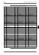
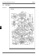
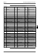
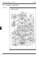
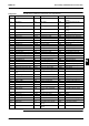
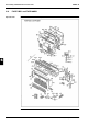
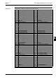
Components The table below contains the components of the exploded view.
No. Component No. Component No. Component
B1 Heat exchanger assy F3 Side plate assy swing unit F13 Decorative frame air dis-
charge
B1.1 Distributor F3.1 Side plate F14 Decorative frame air dis-
charge
B1.2 Union joint (gas line) F3.2 Air swing unit F15 Horizontal vane air dis-
charge
B1.3 Union joint (liquid line) F3.2.1 Air swing motor F16 Horizontal vane air dis-
charge
B1.4 Flare nut F3.2.2 Limit switch F17 Blind plate pipng hole
B1.5 Flare nut F3.2.3 Bearing assy (right) F18 Partition plate evaporator
C1 Rotor assy F3.2.4 Bearing assy (left) F19 Blind plate heat exchanger
C2 Lock nut fan rotor F3.2.5 Joint F20 Fitting plate evaporator
C3 Lock washer F3.2.6 Air swing motor base F21 Retainer refrigerant piping
E1 Electric components assy F3.2.7 Cover air swing motor F22 Cover inspection hole
E2 Switch box F3.2.8 Cam air swing F23 Bell mouth
E3 Set plate control devices F4 Side plate assy F24 Drain hose assy
E4 PCB assy F4.1 Side plate F25 Drain pan assy
E4.1 Printed circuit (control) F4.2 Bearing assy (right) F25.1 Drain plug
E4.1.1 Air thermistor F4.3 Bearing assy (left) F26 Heat insulator (internal)
E4.2 Capacity setting adaptor F5 Hook metal refr. piping F27 Air adjust plate
E5 Printed circuit (power unit) F6 Hook metal F28 Retainer lead wire
E5.1 Fuse F7 Hook metal F29 Retainer thermistor
E6 Terminal block F8 Air suction grille assy F30 Set bolt fan motor
E7 Capacitor F8.1 Air suction grille F31 Vibration isolator fan motor
E8 Terminal block F8.2 Reinforcement plate F32 Set plate drain pump
E9 Wire harness (transmission) F8.3 Air dilection lever assy F32.1 Set base drain pump
E10 Wire harness (power unit) F8.3.1 Lever air suction grille F32.2 Float switch
E11 Wire harness (power unit) F8.3.2 Spring air suction grille F32.3 Buffer rubber drain pump
E12 Wire harness (PCB termi-
nal)
F8.4 Air direction lever assy F34 Set bolt fan motor
E13 Grounding wire F8.5 Air filter F35 Plain washer
E14 Wire clip F8.6 Reinforcement metal grille F36 Air guide plate assy
E15 Wire clip F8.7 DAIKIN name plate K2 Insulation cover (liquid line)
E16 Edge saddle F8.8 Reinforcement plate K3 Insulation tube (gas line)
E17 Cover switch box F9 Corner cover assy K4 Hose band
E18 Housing power unit F9.1 Corner cover K5 Drain hose
E19 Wire harness (fan motor) F9.2 Corner cover K6 Drain pipe joint
E20 Drain pump F10 Corner cover refrigerant
piping
K7 Lead wire remote control
E22 Heat exchanger thermistor F10.1 Corner cover upper K8 Sealer drain hose
E23 Fan motor F10.2 Corner cover lower K9 Staple
E24 Grounding wire F10.3 Internal corner cover K10 Pan head wood screw
F1 Top plate F10.4 Internal corner cover K11 Shelter air discharge grille
F2 Side plate assy F10.5 Tapping screw K12 Lock plate insulator
F2.1 Side plate F11 Decorative frame air dis-
charge
K13 Lock plate insulator
F2.2 Joint assy F12 Decorative frame air dis-
charge
K14 Lock plate insulator