
Specifications
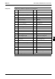
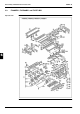
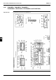

ESIE02–01 Disassembly and Maintenance: Indoor Units
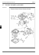
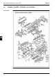
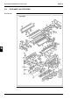
Part 5 – Disassembly and Maintenance 5–41
3
5
1
5
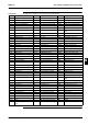
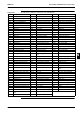
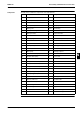
Components The table below contains the components of the exploded view.
No. Component No. Component
B1 Evaporator assy E24 Heat exchanger thermistor
B1.1 Distributor with strainer E25 Fan motor
B1.2 Union joint (gas line) F1 Casing frame assy
B1.3 Union joint (liquid line) F2 Cover inspection window
B1.4 Flare nut F3 Heat insulation cover assy
B1.5 Flare nut F4 Top flat plate
C1 Fan rotor (turbo) F5 Drain pan assy
C2 Lock washer F5.1 Drain plug
C3 Hexagon lock nut F6 Bell mouth
E1 Electric component assy F7 Cover switch box
E2 Switch box F8 Cover switch box
E3 Set plate electric devices F9 Fixture panel
E4 Printed circuit F10 Blind plate heat exchanger
E4.1 Printed circuit F11 Set plate heat exchanger
E4.1.1 Air thermistor F12 Retainer piping
E4.2 Adaptor (capacity control) F13 Rubber bush
E5 Terminal block F14 Vibration isolator fan motor
E6 Terminal block F15 Flange nut
E7 Power transformer F16 Set bolt drain pump
E9 Capacitor F17 Fixture feeler
E10 Tapping screw F20 Bolts and nuts list
E12 Tie wrap G1 Drain hose assy
E13 Wire harness G2 Hose band
E14 Wire harness K1 Drain hose assy
E15 Wire harness K2 Hose band
E18 Wire harness K3 Insulation tube (gas line)
E19 Grounding terminal K4 Insulation tube (liquid line)
E23 Drain pump assy K5 Operation manual
E23.1 Drain pump K6 Sealer drain hose
E23.2 Set plate drain pump K7 Sealer drain hose
E23.3 Float switch —
E23.4 Vibration isolator drain pump