
Specifications


ESIE02–01 Disassembly and Maintenance: Outdoor Units
Part 5 – Disassembly and Maintenance 5–23
3
5
1
5
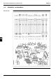
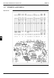
Components
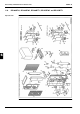
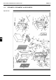
The table below contains the components of the exploded view.
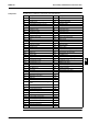
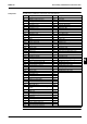
No. Component No. Component
1 Front plate 1 35 Filter
2 Front plate 2 36 Filter
3 Side plate 37 Fan propeller
4 Top plate assy 38 Washer
5 Bottom frame assy 39 Nut with washer
6 Fixation leg 40 Filter
7 Partition plate assy 41 Fan motor
8 DAIKIN name plate 42 Fan motor
9 Stop valve mounting plate 43 Switch box body
10 Fan motor base 44 Magnetic contactor + OC
11 Air discharge grille 45 Starting relay
12 Air suction grille 46 PCB assy
13 Handle 46.1 Glass tube fuse
14 Compressor scroll 47 PCB assy
15 Rubber cushion pre-assy 48 Transformer
16 Nut with washer 49 Air thermistor
17 Bolt for compressor 50 Heat exchanger thermistor
18 Compressor sound absorber 51 Discharge thermistor
19 Heat exchanger 52 Resin PCB support
20 Receiver 53 Running capacitor compressor
21 4-way valve 54 Running capacitor compressor
22 Coil 4-way valve 55 Start capacitor compressor
23 Motor valve body 56 Capacitor fan motor
24 Coil of motor valve 57 Resistor assy
25 Solenoid valve coil 58 Terminal strip
26 Solenoid valve 59 Locking card spacer
27 High-pressure switch 60 Compressor cable assy
28 Low-pressure switch 61 Cable holders
29 Charge valve 62 Clamp for harness
29.1 Valve core (service port) 63 Thermistor fixing plate
29.2 Blind cap (service port) 64 Thermistor mounting spring
30 Stop valve assy 65 Thermistor mounting spring
31 Stop valve assy 66 Stop valve cover
32 Service cap 67 Bottom tray assy
33 Flare nut 68 Packing case shell
34 Flare nut 69 Packing cushion assy