
Specifications

ESIE02–01 Disassembly and Maintenance: Outdoor Units
Part 5 – Disassembly and Maintenance 5–13
3
5
1
5
Components
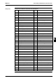
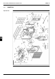
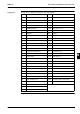
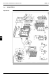
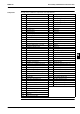
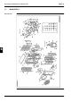
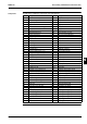
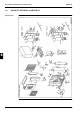
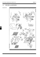
The table below contains the components of the exploded view.
No. Component No. Component
1 Front plate 32 Union joint (liquid line)
2 Side plate back assy 33 Union joint (gas line)
2.1 Handgrip 34 Union joint (gas line)
3 Side plate front assy 35 Union joint (gas line)
3.1 DAIKIN name plate 36 Flare nut
3.2 Handgrip 37 Flare nut
3.3 R407C sticker 38 Flare nut
4 Top plate assy 39 Flare nut
4.1 Wiring diagram 40 Fan motor
5 Air discharge grille assy 41 Propeller fan
6 Suction grille 42 Fan nut
7 Bottom frame assy 43 Switch box assy
8 Service cover assy 43.1 Switch box plate
9 Partition plate 43.2 PCB assy
10 Fan motor stand 43.2.1 Fuse (printed circuit)
11 Piping mounting plate cover assy 43.2.2 Varistor
11.1 Liquid/gas indication N/P 43.3 PCB assy
12 Compressor 43.4 Reverse phase protector
13 Compressor rubber 43.5 Locking card spacer
14 Compressor nut 43.6 Power transformer
15 Terminal cover 43.7 Magnetic contactor
16 Terminal nut 43.8 Magnetic contactor
17 Terminal rubber 43.9 Fan capacitor
18 Compressor set plate assy 43.10 Noise filter
19 Set plate for thermistor 43.11 Surge absorber
20 Compressor sound absorber shell 43.12 Electronic expansion valve coil
21 Accumulator assy 43.13 Terminal strip
22 Heat exchanger assy 43.14 Terminal strip
23 Heat exchanger assy 43.15 Wire clamp (lead wire)
24 Cushion outdoor heat exchanger 43.16 Insulation strip for wire clamp
25 Low pressure control valve 43.17 Wire clamp
26 Motor valve 43.18 Insulation strip for wire clamp
27 Branch pipe 43.19 Low ambient thermostat
28 Stop valve outlet pipe assy 44 Set plate half union joint
29 Strainer 45 Set plate half union joint
30 Stop valve assy (liquid line) 46 Set plate half union joint
30.1 Valve core 47 Set plate half union joint
30.2 Blind cap —
30.3 Valve cap (stop valve)
31 Stop valve assy (gas line)
31.1 Valve core
31.2 Blind cap
31.3 Valve cap (stop valve)