
Specifications

ESIE02–01 Disassembly and Maintenance: Outdoor Units
Part 5 – Disassembly and Maintenance 5–9
3
5
1
5
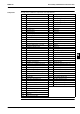
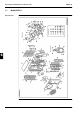
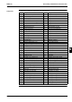
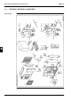
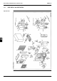
Components
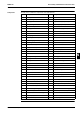
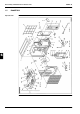
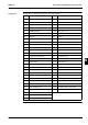
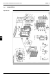
The table below contains the components of the exploded view.
No. Component No. Component
1 Front plate 28 Solenoid valve assy
2 Side plate right rear 29 High-pressure switch
2.1 Handgrip 30 Stop valve assy (liquid line)
3 Side plate right left 30.1 Valve cap (stop valve)
3.1 DAIKIN name plate 31 Flare nut
3.2 Handgrip 32 Stop valve assy (gas line)
3.3 R407C sticker 32.1 Valve core (service port)
4 Top plate 32.2 Cover for service port
4.1 Wiring diagram 32.3 Stop valve cover
4.2 Fault diagnosis name plate 33 Flare nut
5 Air discharge grille assy 34 Fan motor
6 Suction grille 35 Propeller fan assy
7 Bottom frame assy 36 Fan nut
8 Service cover assy 37 Switch box assy
9 Partition plate 37.1 Switch box plate
10 Fan motor stand 37.2 PCB assy
11 Compressor 37.2.1 Varistor
12 Spring holder upper 37.3 Locking guard spacer
13 Spring 37.4 Power transformer
14 Spring holder lower 37.5 Transformer fixing plate
15 Flange nut 37.6 Thermistor assy
16 Terminal cover 37.7 Magnetic contactor
17 Retainer o.l. relay 37.8 Running capacitor
18 Lead wire protection bush 37.9 Capacitor fixing band
19 Compressor sound absorber shell 37.10 Fan capacitor
20 Accumulator 37.11 Set plate for high-pressure switch
21 Accumulator sound absorber shell 37.12 Terminal strip
22 Heat exchanger assy 37.13 Wire clamp
22.1 Service port assy 37.14 Insulation strip for wire clamp
22.1.1 Valve core (service port) 37.15 Filter capacitor assy
22.1.2 Cover for service port 38 Overload protector
23 Heat exchanger fixing plate 39 Outdoor thermistor mounting plate
24 Bypass seal plate 40 Set metal (thermistor use)
25 Cushion outdoor heat exchanger 41 Strainer
26 Capillary assy 42 Accumulator cushion rubber
27 4-way valve body 43 Plate spring