
Service manual


Outdoor Unit Si18-201
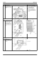
326 Removal Procedure
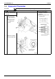
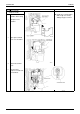
8. Detaching the control
PCB
1
The control PCB is
located as shown at
right.
2
The setting and self-
diagnostic PCB is
located also as shown
at right.
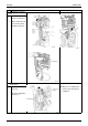
"
The PCB1 and
PCB4 are integrally
constructed.
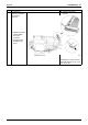
3
Disconnect all the
connectors.
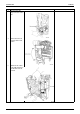
Remove the two
screws from the control
PCB.
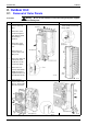
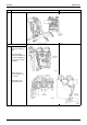
4
Remove the two
screws from the
electrolytic capacitor.
Step Procedure Points