
Service manual

For BPMK928B42 · 43 Si18-201
314 Removal Procedure
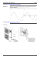
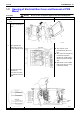
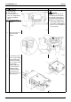
2. Removing the PCB
"
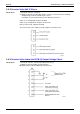
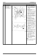
The PCB is treated for
moisture resistance.
Replace the PCB and its
mount together, if required.
"
The LED (green) lights up
while the microcomputer
functions.
"
Self-diagnostic LEDs
LED-A (green)
LED-1 (red)
LED-2 (red)
LED-3 (red)
LED-4 (red)
S4: Motorized valve coil (yellow)
S3: Motorized valve coil (blue)
S2: Motorized valve coil (red)
S1: Motorized valve coil (white)
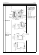
1
The codes of the
connectors on the PCB
are as shown at right.
2
Remove the four
screws from the PCB.
3
Loosen the two
keyhole-provided
screws and remove the
two other screws from
the PCB mount.
Step Procedure Points