Si18-201 Service Manual J Series [Applied Models] !Super Multi Plus : Cooling Only !Super Multi Plus : Heat Pump
Si18-201 Super Multi Plus J Series !Heat Pump Indoor Unit FTX25JVEA9 FTX35JVEA9 FTX25JVEC FTX35JVEC FTX25JAVET FTX35JAVET FTX25JAV1NB FTX35JAV1NB FTXD25KZV1B FTXD35KZV1B FVX25KZV1B FVX35KZV1B FTXD50JVEA9 FTXD60JVEA FTXD71JVEA FTX50HVEC FTX60HVEC FTXD50JVET FTXD60JVET FTXD71JVET FTXD50JV1B FTXD60JV1B FTXD71JV1B CDX25HAVEA CDX35HAVEA CDX50HAVEA CDX60HAVEA CDX25HAVEC CDX35HAVEC CDX50HAVEC CDX60HAVEC CDX25HAV1NB CDX35HAV1NB CDX50HAV1NB CDX60HAV1NB CDX25JV1NB CDX35JV1NB CDX50JV1NB CDX60JV1NB CDX25JVEC CDX35JV
Si18-201 NOTICE : Special specifications Model RMK140JAVM has the following different specifications from the others. Take the important notes below. This model is designed for cooling mode only, which means it has no heating functions at all. ★Important points : The model is not equipped with the receiver circuit. 1) The heating mode is not available because the following parts are not built in.
Si18-201 1. Introduction ............................................................................................ ix 1.1 Safety Cautions ....................................................................................... ix Part 1 List of Function .................................................................. 1 1. List of Function........................................................................................2 1.1 1.2 1.3 1.4 1.5 1.6 1.7 Function List for General .....................
Si18-201 Part 5 Main Functions Outdoor Unit / BP Unit.......................... 101 1. Refrigerant System and Function of Functional Parts of Outdoor Unit....................................................................................103 1.1 Refrigerant System and Function of Functional Parts of Outdoor Unit .....................................................................................103 1.2 Major Functional Parts .........................................................................104 1.
Si18-201 3.38 JIS Mode ..............................................................................................167 3.39 Pump Down Operation .........................................................................168 3.40 Protection Control of SkyAir Indoor Units.............................................169 Part 6 Flow of Refrigerant ........................................................ 171 1. Flow of Refrigerant..............................................................................
Si18-201 1.3 Code Indication on the Remote Controller ...........................................230 1.4 Troubleshooting....................................................................................231 1.5 Troubleshooting Detail .........................................................................232 2. Troubleshooting - SkyAir Indoor Unit ..................................................246 2.1 2.2 2.3 2.4 2.5 2.6 The INSPECTION/TEST Button.....................................................
Si18-201 Part 12 Appendix......................................................................... 359 1. Piping Diagrams..................................................................................360 1.1 Outdoor Units .......................................................................................360 1.2 BP Units ...............................................................................................362 1.3 Indoor Units ..................................................................
Si18-201 viii Table of Contents
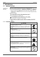
Si18-201 Introduction 1. Introduction 1.1 Safety Cautions Cautions and Warnings " Be sure to read the following safety cautions before conducting repair work. " The caution items are classified into “ Warning” and “ Caution”. The “ Warning” items are especially important since they can lead to death or serious injury if they are not followed closely. The “ Caution” items can also lead to serious accidents under some conditions if they are not followed.
Introduction Si18-201 Caution Do not repair the electrical components with wet hands. Working on the equipment with wet hands can cause an electrical shock. Do not clean the air conditioner by splashing water. Washing the unit with water can cause an electrical shock. Be sure to provide the grounding when repairing the equipment in a humid or wet place, to avoid electrical shocks. Be sure to turn off the power switch and unplug the power cable when cleaning the equipment.
Si18-201 Introduction Warning Be sure to use the specified cable to connect between the indoor and outdoor units. Make the connections securely and route the cable properly so that there is no force pulling the cable at the connection terminals. Improper connections can cause excessive heat generation or fire. When connecting the cable between the indoor and outdoor units, make sure that the terminal cover does not lift off or dismount because of the cable.
Introduction Si18-201 Caution Check to see if the parts and wires are mounted and connected properly, and if the connections at the soldered or crimped terminals are secure. Improper installation and connections can cause excessive heat generation, fire or an electrical shock. If the installation platform or frame has corroded, replace it. Corroded installation platform or frame can cause the unit to fall, resulting in injury. Check the grounding, and repair it if the equipment is not properly grounded.
Si18-201 Part 1 List of Function 1. List of Function........................................................................................2 1.1 1.2 1.3 1.4 1.5 1.6 1.7 Function List for General ..........................................................................2 Function List for China .............................................................................3 Function List for Taiwan ...........................................................................4 Function List for Europe ........
List of Function Si18-201 1.
Si18-201 Function List for China Division Outdoor Unit Cooling Only Indoor Unit Wall Mounted Type Floor/ Ceiling Suspended Dual Type Ceiling Mounted Cassette Type Duct Connected Type Outdoor Unit Heat Pump Indoor Unit Wall Mounted Type Floor/ Ceiling Suspended Dual Type Ceiling Mounted Cassette Type Duct Connected Type List of Function Indoor Unit / Outdoor Unit Inverter (with Inverter Power Control) PAM control (Pulse Amplitude Modulation Control) Horizontal Scroll, Oval Scroll Compressor (DAIKI
List of Function Function List for Taiwan Division Cooling Only Indoor Unit Outdoor Unit Wall Mounted Type Floor/ Ceiling Suspended Dual Type Ceiling Mounted Cassette Type Duct Connected Type Outdoor Unit Heat Pump Indoor Unit Wall Mounted Type 4 Floor/ Ceiling Suspended Dual Type Ceiling Mounted Cassette Type Duct Connected Type Indoor Unit / Outdoor Unit Inverter (with Inverter Power Control) PAM control (Pulse Amplitude Modulation Control) Horizontal Scroll, Oval Scroll Compressor (DAIKIN SCR
Division Outdoor Unit Wall Mounted Type Duct Connected Type Indoor Unit / Outdoor Unit Inverter (with Inverter Power Control) PAM control (Pulse Amplitude Modulation Control) Horizontal Scroll, Oval Scroll Compressor (DAIKIN SCROLL) Reluctance DC Motor Dual Flaps Power-Airflow Dual Flaps Power-Airflow Diffuser Wide-Angle Louvers Vertical Auto-Swing (Up and Down) Horizontal Auto-Swing (Right and Left) 3-D Airflow Auto Fan Speed Silent Operation Control (Automatic) Intelligent Eye Automatic Operation Progr
Cooling Only Indoor Unit 1.
Si18-201 Function List for Australia Division Outdoor Unit Cooling Only Indoor Unit Wall Mounted Type Floor/ Ceiling Suspended Dual Type Ceiling Mounted Cassette Type Duct Connected Type Outdoor Unit Heat Pump Indoor Unit Wall Mounted Type Floor/ Ceiling Suspended Dual Type Ceiling Mounted Cassette Type Duct Connected Type Indoor Unit / Outdoor Unit Inverter (with Inverter Power Control) PAM control (Pulse Amplitude Modulation Control) Horizontal Scroll, Oval Scroll Compressor (DAIKIN SCROLL) Relu
Division Outdoor Unit Wall Mounted Type Duct Connected Type 8 Indoor Unit / Outdoor Unit Inverter (with Inverter Power Control) PAM control (Pulse Amplitude Modulation Control) Horizontal Scroll, Oval Scroll Compressor (DAIKIN SCROLL) Reluctance DC Motor Dual Flaps Power-Airflow Dual Flaps Power-Airflow Diffuser Wide-Angle Louvers Vertical Auto-Swing (Up and Down) Horizontal Auto-Swing (Right and Left) 3-D Airflow Auto Fan Speed Silent Operation Control (Automatic) Intelligent Eye Automatic Operation Pr
Si18-201 Part 2 Specifications 1. Specifications ........................................................................................10 1.1 1.2 1.3 1.4 1.5 1.6 Outdoor Units .........................................................................................10 BP Units .................................................................................................18 Indoor Units (for General).......................................................................19 Indoor Units (for China) ......
Specifications Si18-201 1. Specifications 1.1 Outdoor Units 1.1.1 Cooling Only 50Hz 220-240V / 60Hz 220-230V Model RMK140JVMC9 (8) Cooling Capacity (19.0°CWB) kW kcal/h 14.5 12,470 W A 5,000 23.2 Power Consumption ★ Running Current ★ Casing Color Ivory White Hermetically Sealed Scroll Type (Oval Discharge) Type Compressor Model JT100FBVD Motor Output Refrigerant Oil Refrigerant W 3,300 Model SUNISO 4GSD.I. Charge kg 1.5 Type R22 Charge m³/min Air Flow Rate cfm kg 9.
Si18-201 Specifications 60Hz 220V Model RMK140JVMT9 Cooling Capacity (19.5°CWB) Power Consumption ★ kW 14.5 kcal/h W 12,500 4,950 Running Current ★ A 23.0 Casing Color Compressor Ivory White Type Model Hermetically Sealed Scroll Type (Oval Discharge) JT100FBVD Motor Output Refrigerant Oil Refrigerant W 3,300 Model SUNISO 4GSD.I. Charge Type kg Charge kg 9.9 H 114 L H 104 4,024 m³/min Air Flow Rate cfm 1.
Specifications Si18-201 50Hz 220-230-240V / 60Hz 220-230V Model RMK140JAVM Cooling Capacity (19.0°CWB) Power Consumption ★ kW 14.5 kcal/h W 12,470 4,650 Running Current ★ A 20.4 Casing Color Compressor Ivory White Type Model Hermetically Sealed Scroll Type (Oval Discharge) JT100FBVD Motor Output Refrigerant Oil Refrigerant W 3,300 Model SUNISO 4GSD.I. Charge Type kg Charge kg 4.5 H 114 L H 104 4,024 m³/min Air Flow Rate cfm 1.
Si18-201 Specifications 50Hz 220-230-240V / 60Hz 220-230V Model RMK140JZVMA Cooling Capacity (19.0°CWB) Power Consumption ★ kW 14.5 kcal/h W 12,470 5,000 A 23.2-22.2-21.3 Running Current ★ Casing Color Compressor Ivory White Type Model Hermetically Sealed Scroll Type (Oval Discharge) JT100FAVD Motor Output Refrigerant Oil Refrigerant W 3,300 Model DAPHNE FVC68D Charge Type kg Charge kg 9.9 H 114 L H 104 4,024 m³/min Air Flow Rate cfm 1.
Specifications Si18-201 1.1.2 Heat Pump 50Hz 220-240V / 60Hz 220-230V RMX140JVMC9 (8) Model Cooling Heating kW 14.5 16.5 kcal/h 12,470 14,190 Power Consumption ★ W 5,000 5,780 Running Current ★ A 23.2 Cooling Capacity (19.0°CWB) 26.8 Casing Color Compressor Ivory White Type Model Hermetically Sealed Scroll Type (Oval Discharge) JT100FBVD Motor Output Refrigerant Oil Refrigerant W 3,300 Model SUNISO 4GSD.I. Charge Type L Charge kg 9.
Si18-201 Specifications 60Hz 220-230V RMX140JVMT9 Model Cooling Cooling Capacity (19.5°CWB) Heating kW 14.5 16.5 kcal/h 12,500 14,200 W A 4,950 23.0 5,870 27.2 Power Consumption ★ Running Current ★ Casing Color Ivory White Type Compressor Refrigerant Oil Refrigerant Hermetically Sealed Scroll Type (Oval Discharge) Model Motor Output Model SUNISO 4GSD.I. Charge L 1.5 kg R22 9.
Specifications Si18-201 50Hz 220-240V / 60Hz 220-230V RMX140JVMB Model Cooling Cooling Capacity (19.0°CWB) Heating kW 14.5 16.5 kcal/h 12,470 14,190 W A 5,000 23.2 5,780 26.8 Power Consumption ★ Running Current ★ Casing Color Ivory White Type Compressor Refrigerant Oil Refrigerant Hermetically Sealed Scroll Type (Oval Discharge) Model Motor Output Model SUNISO 4GSD.I. Charge L 1.5 kg R22 9.
Si18-201 Specifications 50Hz 220-230-240V / 60Hz 220-230V RMX140JZVMB Model Cooling Cooling Capacity (19.0°CWB) Heating kW 14.5 16.5 kcal/h 12,470 14,190 W A 5,000 23.2-22.2-21.3 6,050 28.1-26.8-25.7 Power Consumption ★ Running Current ★ Casing Color Ivory White Type Compressor Refrigerant Oil Refrigerant Hermetically Sealed Scroll Type (Oval Discharge) Model Motor Output Model DAPHNE FVC68D Charge L 1.5 kg R407C 9.
Specifications 1.2 Si18-201 BP Units 50Hz 220-240V / 60Hz 220-230V Model Connectable Indoor Units Capacity BPMK928B42 BPMK928B43 1~2 Units 1~3 Units — Cooling kW — Heating kW — Casing Color — Paintingless Power Consumption W 10 10 Running Current A 0.05 0.05 Refrigerant Type — Charge Dimensions (H×W×D) Package Dimensions kg — mm mm 223×400×272 651×342×281 Machine Weight kg 7 8 Gross Weight kg 10 11 mm Main : φ9.5×1/ Branch : φ6.4×2 Main : φ9.5×1/ Branch : φ6.
Si18-201 1.3 Specifications Indoor Units (for General) 1.3.1 Cooling Only " Wall Mounted Type " 2.5kW Class 50Hz 220-230-240V / 60Hz 220-230V FTK25JVE9 Model Rating Capacity kW Front Panel Color Almond White m³/min Air Flow Rates cfm Fan FTK25JVEA9 2.5 Type Motor Output Speed H 7.5 M 6.4 L H 5.
Specifications Si18-201 " 5.0kW Class 50Hz 220-230-240V / 60Hz 220-230V Model FTKD50JVE Rating Capacity kW Front Panel Color Almond White H 12.9 m³/min M L 11.4 9.9 H 455 cfm M 402 L 349 Cross Flow Fan Air Flow Rates Type Fan FTKD50JVEA9 5.0 Motor Output Speed W 54 Steps 5 Steps and Auto Air Filter Removal / Washable / Mildew Proof Running Current ★ (Rated) A Power Consumption ★ (Rated) W 40 Power Factor ★ % 95.7-96.7-98.0 / 95.7-96.7 0.19-0.18-0.17 / 0.19-0.
Si18-201 Specifications " 7.1kW Class 50Hz 220-230-240V / 60Hz 220-230V Model FTKD71JVE Rating Capacity kW Front Panel Color Almond White H 14.3 m³/min M L 12.3 10.4 H 505 cfm M 434 L 367 Cross Flow Fan Air Flow Rates Type Fan FTKD71JVEA 7.1 Motor Output Speed W 54 Steps 5 Steps and Auto Air Filter Removal / Washable / Mildew Proof Running Current ★ (Rated) A Power Consumption ★ (Rated) W 50 Power Factor ★ % 98.8-98.8-99.2 / 98.8-98.8 0.23-0.22-0.21 / 0.23-0.
Specifications Si18-201 " Duct Connected Type " 2.5kW Class 50Hz 220-230-240V / 60Hz 220-230V Model CDK25HAVE Rating Capacity 2.5 H 13.0 m³/min M L 12.0 11.0 H 459 cfm M 424 L 388 Sirocco Fan Front Panel Color — Air Flow Rates Type Fan CDK25HAVEA kW Motor Output W 47 Steps 5 Steps and Auto Running Current ★ (Rated) A — 0.40 - 0.40 - 0.40 / 0.43 - 0.43 Power Consumption ★ (Rated) Power Factor ★ W % 85 - 85 - 90 / 90 - 90 96.6 - 92.4 - 93.8 / 95.1 - 91.
Si18-201 Specifications " 5.0kW Class 50Hz 220-230-240V / 60Hz 220-230V Model CDK50HAVE Rating Capacity 5.0 H 13.0 m³/min M L 12.0 11.0 H 459 cfm M 424 Front Panel Color — Air Flow Rates L 388 Type Fan CDK50HAVEA kW Sirocco Fan Motor Output Speed W Steps 47 5 Steps and Auto Air Filter Running Current ★ (Rated) A 0.40 - 0.40 - 0.40 / 0.43 - 0.43 Power Consumption ★ (Rated) W 85 - 85 - 90 / 90 - 90 Power Factor ★ % 96.6 - 92.4 - 93.8 / 95.1 - 91.
Specifications Si18-201 " Floor/Ceiling Suspended Dual Type " 2.5kW Class 50Hz 220-230-240V / 60Hz 220-230V Model FLK25HVE Rating Capacity kW Front Panel Color Almond White H 7.6 m³/min M L 6.8 6.0 H 268 cfm M 240 L 212 Sirocco Fan Air Flow Rates Type Fan FLK25HVEA 2.5 Motor Output W 34 Steps 5 Steps and Auto Running Current ★ (Rated) A Removable / Washable / Mildew Proof 0.32 - 0.32 - 0.32 / 0.34 - 0.
Si18-201 Specifications " 5.0kW Class 50Hz 220-230-240V / 60Hz 220-230V Model FLK50HVE Rating Capacity FLK50JVEA9 kW 5.0 Front Panel Color Almond White H 11.4 11.4 m³/min M L 10.0 8.5 9.9 8.5 H 402 402 cfm M 351 349 L 300 Air Flow Rates 300 Type Fan Sirocco Fan Motor Output Speed W Steps 34 5 Steps and Auto Air Filter Running Current ★ (Rated) A Removable / Washable / Mildew Proof Power Consumption ★ (Rated) W 94 - 96 - 98 / 98 - 101 Power Factor ★ % 94.2 - 92.
Specifications Si18-201 " Ceiling Mounted Cassette Type (SkyAir) " 3.75kW Class · 5.2kW Class Model 50Hz 220-230-240V / 60Hz 220-230V FHYC35KVE9 Rating Capacity kW Front Panel Color 5.2 White m³/min Air Flow Rates cfm H 14.0 15.0 L H 10.0 494 11.0 530 L 353 Type Fan FHYC50KVE9 3.75 388 Turbo Fan Motor Output Speed W 45 Steps 2 Steps and Auto Air Filter Running Current ★ (Rated) A 0.8 - 0.8 / 0.9 Power Consumption ★ (Rated) Power Factor ★ W % 140 - 140 / 161 79.5 - 72.9 / 81.
Si18-201 Specifications " Duct Connected Type (SkyAir) " 6.15kW Class · 7.7kW Class Model 50Hz 220-230-240V FDYM60FAV1 Rating Capacity kW 6.15 Front Panel Color m³/min Air Flow Rates cfm 7.7 H — 20 L H — 706 L — Type Fan FDYM03FAV1 Sirocco Fan Motor Output W 125 Steps 2 Step and Auto Air Filter Running Current ★ (Rated) A 0.9 Power Consumption ★ (Rated) Power Factor ★ W % 170 85.
Specifications Si18-201 1.3.2 Heat Pump " Wall Mounted Type " 2.5kW Class · 3.5kW Class 50Hz 220-230-240V / 60Hz 220-230V FTX25JVEA9 Model Rating Capacity Front Panel Color kW Heating Cooling Heating 2.5 3.4 3.5 4.2 7.8 6.7 8.7 7.4 Almond White H M m³/min Air Flow Rates cfm Type Motor Output Fan FTX35JVEA9 Cooling 7.5 6.4 8.8 7.5 L 5.4 6.2 5.5 6.
Si18-201 Specifications " 7.1kW Class 50Hz 220-230-240V / 60Hz 220-230V FTXD71JVEA Model Cooling Rating Capacity Front Panel Color kW Heating 7.1 8.5 Almond White m³/min Air Flow Rates cfm H 14.3 M 12.3 18.1 14.9 L H 10.4 505 11.7 639 M 434 526 L 367 413 Type Fan Cross Flow Fan Motor Output Speed W 54 Steps 5 Steps and Auto Removal / Washable / Mildew Proof Air Filter Running Current ★ (Rated) A W 0.23-0.22-0.21 / 0.23-0.22 50 Power Factor ★ Temperature Control % 98.
Specifications Si18-201 " Duct Connected Type " 2.5kW Class · 3.5kW Class 50Hz 220-230-240V / 60Hz 220-230V CDX25HAVEA Model Rating Capacity kW CDX35HAVEA Cooling Heating Cooling Heating 2.5 3.86 3.5 4.42 Front Panel Color — m³/min Air Flow Rates cfm H 13.0 M 12.0 L 11.0 H 459 M L 424 388 Type Fan Sirocco Fan Motor Output Speed W 47 Steps 5 Steps and Auto — 0.40 - 0.40 - 0.40 / 0.43 - 0.
Si18-201 Specifications " Floor / Ceiling Suspended Dual Type " 2.5kW Class · 3.5kW Class 50Hz 220-230-240V / 60Hz 220-230V FLX25HVEA Model Rating Capacity Front Panel Color kW FLX35HVEA Cooling Heating Cooling Heating 2.5 3.86 3.5 4.42 Almond White m³/min Air Flow Rates cfm H 7.6 9.2 8.7 10.0 M 6.8 8.3 7.7 9.0 L 6.0 7.4 6.6 8.
Specifications Si18-201 " Ceiling Mounted Cassette Type (SkyAir) " 3.75kW Class · 5.2kW Class Model Rating Capacity Front Panel Color FHYC50KVE9 Cooling Heating Cooling Heating 3.75 4.22 5.2 5.8 White m³/min Air Flow Rates cfm Fan 50Hz 220-230-240V / 60Hz 220-230V FHYC35KVE9 Type Motor Output H 14.0 15.0 L 10.0 11.0 H 494 530 L 353 388 Turbo Fan 45 W Speed Steps 2 Steps and Auto Air Filter Resin Net (with Mold Resistant) Running Current ★ (Rated) A 0.8 - 0.8 / 0.9 0.
Si18-201 Specifications " Duct Connected Type (SkyAir) " 6.0kW Class · 7.7kW Class 50Hz 220-230-240V FDYM60FAV1 Model Rating Capacity Front Panel Color FDYM03FAV1 Cooling Heating Cooling Heating 6.0 7.0 7.7 7.9 — H m³/min Air Flow Rates cfm — H 706 L — W Sirocco Fan 125 Steps 2 Step and Auto Running Current ★ (Rated) A 0.9 Power Consumption ★ (Rated) W 170 Power Factor ★ % 85.9 Fan Type Motor Output 20.
Specifications 1.4 Si18-201 Indoor Units (for China) 1.4.1 Cooling Only " Wall Mounted Type 50Hz 220V Model FTK25JVEC Rating Capacity kW Front Panel Color H M m³/min Air Flow Rates cfm Fan Type Motor Output Speed FTK35JVEC 2.5 3.5 Almond White Almond White 7.5 6.4 7.5 6.5 L 5.5 5.
Si18-201 Specifications " Duct Connected Type 50Hz 220V Model Rating Capacity kW Front Panel Color CDK35HAVEC 2.5 3.5 — — H 13.0 13.0 m³/min M L 12.0 11.0 12.0 11.0 H 459 459 cfm M 424 424 L 388 Sirocco Fan 388 Sirocco Fan Air Flow Rates Type Fan CDK25HAVEC Motor Output W 47 47 Steps 5 Steps and Auto 5 Steps and Auto Running Current ★ (Rated) A — 0.40 — 0.40 Power Consumption ★ (Rated) Power Factor ★ W % 85 96.6 85 96.
Specifications Si18-201 " Floor / Ceiling Suspended Dual Type 50Hz 220V Model FLK25HVEC Rating Capacity kW Front Panel Color 2.5 3.5 Almond White Almond White H 7.6 8.7 m³/min M L 6.8 6.0 7.7 6.6 H 268 307 cfm M 240 270 L 212 233 Sirocco Fan Sirocco Fan 34 5 Steps and Auto 34 5 Steps and Auto Air Flow Rates Type Fan FLK35HVEC Motor Output Speed W Steps Air Filter Running Current ★ (Rated) Removable / Washable / Mildew Proof Removable / Washable / Mildew Proof A 0.
Si18-201 Specifications " Ceiling Mounted Cassette Type (SkyAir) 50Hz 220V Model FHYC35KV1C9 Rating Capacity kW FHYC60KV1C9 5.2 6.15 3.75 Front Panel Color White m³/min Air Flow Rates cfm Speed 7.7 H 14.0 15.0 L H 10.0 494 11.0 530 14.0 671 L 353 388 494 Turbo Fan Motor Output FHYC71KV1C9 White 19.0 Type Fan FHYC50KV1C9 Turbo Fan W 45 45 Steps 2 Steps and Auto 2 Steps and Auto Air Filter Running Current ★ (Rated) A 0.8 Resin Net (with Mold Resistant) 0.8 0.
Specifications Si18-201 1.4.2 Heat Pump " Wall Mounted Type 50Hz 220V FTX25JVEC Model Rating Capacity Front Panel Color kW H M Air Flow Rates cfm Type Motor Output Heating Cooling 2.5 3.4 3.5 Running Current ★ (Rated) Power Consumption ★ (Rated) 8.5 7.3 8.7 7.5 5.4 6.2 5.5 6.
Si18-201 Specifications " Duct Connected Type 50Hz 220V CDX25HAVEC Model Rating Capacity Front Panel Color kW Cooling Heating Cooling 2.5 3.86 3.5 Air Flow Rates cfm — H 13.0 13.0 13.0 M 12.0 12.0 12.0 12.0 L 11.0 11.0 11.0 11.0 H 459 459 459 459 M L 424 388 424 388 424 388 424 388 Type 13.0 Sirocco Fan Motor Output Speed Heating 4.
Specifications Si18-201 " Duct Connected Type 50Hz 220V CDX25JVEC Model Rating Capacity Front Panel Color kW Cooling Heating Cooling 2.5 3.86 3.5 Air Flow Rates cfm — H 10.4 10.4 11.0 11.0 M 9.6 9.6 10.2 10.2 L 8.7 8.7 9.3 9.3 H 367 367 388 388 M L 339 307 339 307 360 328 360 328 Type Sirocco Fan Motor Output Speed Heating 4.
Si18-201 Specifications " Floor / Ceiling Suspended Dual Type 50Hz 220V FLX25HVEC Model Rating Capacity Front Panel Color kW Cooling Heating Cooling 2.5 3.86 3.5 Air Flow Rates cfm Almond White H 7.6 9.2 8.7 10.0 M 6.8 8.3 7.7 9.0 L 6.0 7.4 6.6 8.0 H 268 325 307 353 M L 240 212 293 261 270 233 318 282 Type Sirocco Fan Motor Output Speed Heating 4.
Specifications Si18-201 " Ceiling Mounted Cassette Type (SkyAir) 50Hz 220V FHYC35KV1C9 Model Rating Capacity Front Panel Color FHYC60KV1C9 m³/min cfm Type Motor Output Heating Cooling Heating Cooling Heating Cooling Heating 3.75 4.22 5.2 5.8 6.15 7.0 7.7 7.9 White H 14.0 15.0 19.0 L 10.0 11.0 14.
Si18-201 1.5 Specifications Indoor Units (for Taiwan) 1.5.1 Cooling Only " Wall Mounted Type " 2.5, 3.5kW Class 60Hz 220V FTK25JAVET Model Rating Capacity kW 2.5 Front Panel Color 3.5 Almond White H M m³/min Air Flow Rates cfm Fan FTK35JAVET Type Motor Output 7.5 6.4 L 5.4 5.5 H 265 275 M 226 237 L 191 194 Cross Flow Fan 18 W Speed 7.8 6.
Specifications Si18-201 " 7.1kW Class 60Hz 220V Model FTKD71JVET Rating Capacity kW Front Panel Color H 14.3 m³/min M L 12.3 10.4 H 505 cfm M 434 L 367 Cross Flow Fan Air Flow Rates Type Fan 7.1 Almond White Motor Output Speed W 54 Steps 5 Steps and Auto Air Filter Removal / Washable / Mildew Proof Running Current ★ (Rated) A Power Consumption ★ (Rated) W 50 Power Factor ★ % 98.8 Temperature Control 0.
Si18-201 Specifications " Duct Connected Type 60Hz 220V Model Rating Capacity kW Front Panel Color CDK35HAVET 2.5 3.5 — — H 13.0 13.0 m³/min M L 12.0 11.0 12.0 11.0 H 459 459 cfm M 424 424 L 388 Sirocco Fan 388 Sirocco Fan Air Flow Rates Type Fan CDK25HAVET Motor Output W 47 47 Steps 5 Steps and Auto 5 Steps and Auto Running Current ★ (Rated) A — 0.48 — 0.48 Power Consumption ★ (Rated) Power Factor ★ W % 100 94.7 100 94.
Specifications Si18-201 " Floor / Ceiling Suspended Dual Type 60Hz 220V Model FLK25HVET Rating Capacity kW Front Panel Color 2.5 3.5 Almond White Almond White H 7.6 8.7 m³/min M L 6.8 6.0 7.7 6.6 H 268 307 cfm M 240 270 L 212 233 Sirocco Fan Sirocco Fan 34 5 Steps and Auto 34 5 Steps and Auto Air Flow Rates Type Fan FLK35HVET Motor Output Speed W Steps Air Filter Running Current ★ (Rated) Removable / Washable / Mildew Proof Removable / Washable / Mildew Proof A 0.
Si18-201 Specifications " Ceiling Mounted Cassette Type (SkyAir) 60Hz 220V Model FHYC35KVE9 Rating Capacity kW FHYC60KVE9 5.2 6.15 3.75 Front Panel Color White m³/min Air Flow Rates cfm Speed 7.7 H 14.0 15.0 L H 10.0 494 11.0 530 14.0 671 L 353 388 494 Turbo Fan Motor Output FHYC71KVE9 White 19.0 Type Fan FHYC50KVE9 Turbo Fan W 45 45 Steps 2 Steps and Auto 2 Steps and Auto Air Filter Running Current ★ (Rated) A 0.9 Resin Net (with Mold Resistant) 0.9 1.
Specifications Si18-201 1.5.2 Heat Pump " Wall Mounted Type " 2.5kW Class · 3.5kW Class 60Hz 220V FTX25JAVET Model Rating Capacity Front Panel Color kW Cooling Heating Cooling Heating 2.5 3.4 3.5 4.2 7.8 6.7 8.7 7.4 Almond White H M m³/min Air Flow Rates cfm Type Motor Output Fan FTX35JAVET 7.5 6.4 8.8 7.5 L 5.4 6.2 5.5 6.2 H 265 311 275 307 M L 226 191 265 219 237 194 261 219 Cross Flow Fan 18 W Speed Steps 5 Steps and Auto Removal / Washable / Mildew Proof A W 0.
Si18-201 Specifications " 7.1kW Class 60Hz 220V FTXD71JVET Model Cooling Rating Capacity Front Panel Color kW 8.5 Almond White m³/min Air Flow Rates cfm H 14.3 M 12.3 14.9 L H 10.4 505 11.7 639 18.1 M 434 526 L 367 413 Type Fan Heating 7.1 Cross Flow Fan Motor Output Speed W 54 Steps 5 Steps and Auto Removal / Washable / Mildew Proof Air Filter Running Current ★ (Rated) A W 0.23 50 Power Factor ★ Temperature Control % 98.
Specifications Si18-201 " Floor / Ceiling Suspended Dual Type 60Hz 220V FLX25HVET Model Cooling Rating Capacity Front Panel Color kW m³/min Air Flow Rates cfm Heating Cooling 2.5 kW Class Almond White H 7.6 9.2 8.7 10.0 6.8 8.3 7.7 9.0 L 6.0 7.4 6.6 8.0 H 268 325 307 353 M L 240 212 293 261 270 233 318 282 Sirocco Fan Motor Output Speed Heating 3.
Si18-201 Specifications " Ceiling Mounted Cassette Type (SkyAir) 60Hz 220V FHYC35KVE9 Model Rating Capacity Front Panel Color kW FHYC60KVE9 FHYC71KVE9 Cooling Heating Cooling Heating Cooling Heating Cooling Heating 3.75 4.22 5.2 5.8 6.15 7.0 7.7 7.9 White m³/min Air Flow Rates cfm Fan FHYC50KVE9 Type Motor Output H 14.0 15.0 19.0 L 10.0 11.0 14.
Specifications 1.6 Si18-201 Indoor Units (for Europe) 1.6.1 Heat Pump " Wall Mounted Type " 2.5kW Class · 3.5kW Class 50Hz 230V FTX25JAV1NB Model Rating Capacity kW FTX35JAV1NB Cooling Heating Cooling Heating 2.5 3.4 3.5 4.2 Front Panel Color Almond White m³/min Air Flow Rates cfm H 7.1 8.4 7.4 8.4 M 5.9 7.0 6.0 7.1 L 4.6 5.7 4.7 5.
Si18-201 Specifications " 5.0kW Class · 6.0kW Class 50Hz 230V FTXD50JV1B Model Rating Capacity Front Panel Color kW FTXD60JV1B Cooling Heating Cooling Heating 5.0 6.5 6.0 7.2 Almond White m³/min Air Flow Rates cfm H 12.3 14.9 13.0 16.5 M 10.7 12.8 11.5 13.7 L H 9.1 434 10.5 526 9.9 459 11.
Specifications Si18-201 " Duct Connected Type " 2.5kW Class · 3.5kW Class 50Hz 230V CDX25HAV1NB Model Rating Capacity kW CDX35HAV1NB Cooling Heating Cooling Heating 2.5 3.86 3.5 4.42 39 37 40 38 36 36 Front Panel Color — m³/min Air Flow Rates cfm H 13.0 M 12.0 L 11.0 H 459 M L 424 388 Type Fan Sirocco Fan Motor Output Speed W 47 Steps 5 Steps and Auto — 0.40 Air Filter Running Current ★ (Rated) A Power Consumption ★ (Rated) W 85 Power Factor ★ % 92.
Si18-201 Specifications " 2.5kW Class · 3.5kW Class 50Hz 230V CDX25JV1NB Model Rating Capacity kW CDX35JV1NB Cooling Heating Cooling Heating 2.5 3.86 3.5 4.42 Front Panel Color — m³/min Air Flow Rates cfm H 13.0 M 12.0 L 11.0 H 459 M L 424 388 Type Fan Sirocco Fan Motor Output Speed W 47 Steps 5 Steps and Auto Removable / Washable / Mildew Proof 0.40 Air Filter Running Current ★ (Rated) A Power Consumption ★ (Rated) W 85 Power Factor ★ % 92.
Specifications Si18-201 " Floor / Ceiling Suspended Dual Type " 2.5kW Class · 3.5kW Class 50Hz 230V FLX25HV1NB Model Rating Capacity Front Panel Color kW FLX35HV1NB Cooling Heating Cooling Heating 2.5 3.86 3.5 4.42 Almond White m³/min Air Flow Rates cfm H 7.6 9.2 8.7 10.0 M 6.8 8.3 7.7 9.0 L 6.0 7.4 6.6 8.
Si18-201 Specifications " Floor Standing Type " 2.5kW Class · 3.5kW Class 50Hz 230V FVX25KZV1B Model Rating Capacity Front Panel Color kW FVX35KZV1B Cooling Heating Cooling Heating 2.5 3.4 3.5 4.2 Almond White m³/min Air Flow Rates cfm H 8.1 9.2 8.3 9.2 M 6.2 7.0 6.3 7.1 L 4.3 4.8 4.3 5.
Specifications 58 Si18-201 Specifications
Si18-201 Part 3 Printed Circuit Board Connector Wiring Diagram and Name 1. Printed Circuit Board Connector Wiring Diagram and Name ................60 1.1 Branch Provider Unit BPMK928B42, B43 ..............................................60 1.2 Outdoor Unit RMK (X) 140JVMT (C) 9 (8), RMK140JAVM, RMX140JVMB, RMK (X) 140JZVMA (B) ...............................................61 1.3 FTK25 / 35J Series, FTX25 / 35J Series, FTXD25 / 35K Series, FVX25 / 35K Series.................................................
Printed Circuit Board Connector Wiring Diagram and Name Si18-201 1. Printed Circuit Board Connector Wiring Diagram and Name 1.
Si18-201 1.
Printed Circuit Board Connector Wiring Diagram and Name Si18-201 Other Designations 1) H1P (LED A on PCB 4) 2) H2P (PCB 1) 3) H3P (PCB 3) 4) H4P (PCB 3) 5) LED 2~4 (PCB 4) 6) SW1, SW2 (PCB 4) 7) SW3 (PCB 4) 8) SW4 (PCB 4) 9) SW5 (PCB 4) 10) SW6 (PCB 4) 11) SW7 (PCB 4) 12) FU1 (PCB 1) 13) JP LED for Outdoor Unit Status-normal LED for Outdoor Unit Status-normal LED for Outdoor Unit Fan Status-normal LED for Outdoor Unit Fan Status-normal Digital Service Monitor Address Selection Switches Forced Operation M
Si18-201 Printed Circuit Board Connector Wiring Diagram and Name Printed Circuit Board (2) (Filter PCB) Printed Circuit Board (3) (Fan Control) Printed Circuit Board (4) (Indicator PCB) Printed Circuit Board Connector Wiring Diagram and Name 63
Printed Circuit Board Connector Wiring Diagram and Name 1.
Si18-201 Printed Circuit Board Connector Wiring Diagram and Name Printed Circuit Board (1)~(3) S1 Control P C B (1) Signal receive P C B (2) S27 GRN YLW GRN LED1 LED2 LED3 SW7 12V check Jumper S7 ground Intelligent eye sensor P C B (3) JA JB JC S6 5V check Jumper S36 S21 S32 S26 S35 (RL001) Printed Circuit Board (1)~(3) Detail Printed Circuit Board Connector Wiring Diagram and Name 65
Printed Circuit Board Connector Wiring Diagram and Name 1.
Si18-201 Printed Circuit Board Connector Wiring Diagram and Name Printed Circuit Board (2) (Power Supply PCB) Printed Circuit Board (3) (Display PCB) Printed Circuit Board (4) (Signal Receiver PCB) Printed Circuit Board Connector Wiring Diagram and Name 67
Printed Circuit Board Connector Wiring Diagram and Name 1.
Si18-201 Printed Circuit Board Connector Wiring Diagram and Name Printed Circuit Board (1)~(3) S1 Control P C B (1) 12V check Jumper S7 ground sensor P C B (3) JA JB JC S6 5V check Jumper S36 S21 S26 S35 (RL001) Printed Circuit Board (1)~(3) Detail Printed Circuit Board Connector Wiring Diagram and Name 69
Printed Circuit Board Connector Wiring Diagram and Name 1.
Si18-201 Printed Circuit Board Connector Wiring Diagram and Name Printed Circuit Board (1) (Control PCB) Printed Circuit Board (2) (Power Supply PCB) Printed Circuit Board Connector Wiring Diagram and Name 71
Printed Circuit Board Connector Wiring Diagram and Name Si18-201 Printed Circuit Board (3) (Display PCB) Printed Circuit Board (4) (Signal Receiver PCB) 72 Printed Circuit Board Connector Wiring Diagram and Name
Si18-201 1.
Printed Circuit Board Connector Wiring Diagram and Name Si18-201 Printed Circuit Board 74 Printed Circuit Board Connector Wiring Diagram and Name
Si18-201 1.
Printed Circuit Board Connector Wiring Diagram and Name Si18-201 Printed Circuit Board 76 Printed Circuit Board Connector Wiring Diagram and Name
Si18-201 Part 4 Main Functions Indoor Unit 1. Main Functions......................................................................................78 1.1 Main Functions in Split Type ..................................................................78 1.2 SkyAir .....................................................................................................98 1.3 Cautions when SkyAir [Auto] [FAN] are used.......................................100 The RMK140JAVM specifications are special.
Main Functions Si18-201 1. Main Functions 1.1 Main Functions in Split Type 1.1.1 Power-Airflow Flap & Diffuser For FTK, FTX50/ 60 H Series Only The large flaps send ample volume of warm air downward to heat the feet of people in the room, while the wide-angle diffuser ensures the air reaches every corner of the room. The upper and lower flaps located at the air outlet provide optimum air flow control in the cooling, heating and dry modes.
Si18-201 Main Functions Temperature Distribution Air conditioner 24ºC 25ºC 26ºC 28ºC 1m 2m 3m 4m 5m 6m 5m 6m 0m Air conditioner 1m 28ºC 1m 26ºC 1m 2m 3m 4m 6.4m (ML024) < Conditions > Outside temperature: 7ºCDB, thermostat setting: 23ºC, air flow setting: High (H tap), approximately 40 minutes after operation start, height of air outlet: approx. 2 m. *Note that temperature distribution varies depending on the heat insulation, furniture arrangement and other factors in the room. 1.1.
Main Functions Flap Angle Si18-201 During Heating During Cooling Capable of sending air to the center of a room even if it is installed at a corner of the room. 1.1.3 Horizontal Auto-Swing (Up and Down) For FTK, FTX50/ 60 H Series Only Auto-swing angles are about “A” degrees when the fan is ON, and about “B” degrees when the cooling or program dry operation is ON. The up-and-down swing of the flaps widens the direction of wind.
Si18-201 Main Functions Cooling, Dry, Operation (For Cooling Only Model) FTK50/60H Series A B FTK50/60H Series A B Cooling Dry 20º 15º ↔ 40º 20º 15º ↔ 40º Cooling, Dry, Heating Operation (For Heat Pump Model) Cooling Dry Heating 20º 15º ↔ 40º 20º 15º ↔ 40º 20º ↔ 40º 30º ↔ 60º Note: Notes on flap angles The diffuser is kept open in DRY, COOL or FAN mode. Note: Unless [SWING] is selected, you should set the flap at a near-horizontal angle in COOL or DRY mode to obtain the best performance.
Main Functions Si18-201 1.1.4 Wide Angle Flaps, Louvers and Auto-Swing For FTK(X)25/35J Series Only Outline of the Action It can be commanded for J type by means of a user setting to select either any one desired position among the five-step directions of air flow adjusted on a remote controller, or Autoswing.
Si18-201 Main Functions Heating (In The Case of SwingOFF Start) Heating (In The Case of SwingON Start) Note: Main Functions The flaps remain in the preset position for about 10 seconds before they return to the full-open processing.
Main Functions Si18-201 1.1.6 Fan Speed Control for Indoor Units For FTK(X)25/35J, FTK(X)50/60 H Series Control Mode The airflow rate can be automatically controlled depending on the difference between the set temperature and the room temperature. This is done through phase control and Hall IC control. For more information about Hall IC, refer to ‘Hall IC check (A6)’ on page 309. Phase Steps Phase control and fan speed control contains 8 steps: LLL, LL, L, ML, M, HM, H and HH.
Si18-201 Main Functions 1.1.7 ON/OFF Button on Indoor Unit For FTK, FTX50/ 60 H Series Only An ON/OFF switch is provided on the front panel of the unit. Use this switch when the remote controller is missing or if its battery has run out. Every press of the switch changes from Operation to Stop or from Stop to Operation " Push this button once to start operation. Push once again to stop it. " This button is useful when the remote controller is missing. " The operation mode refers to the following table.
Main Functions Clean the Front Grille. Si18-201 " You may wipe it with a soft cloth soaked in water. " Only neutral detergent may be used. " You may wash the grille with water. After washing, dry it with cloth, then dry it up in the shade. Attach the Front Grille. " Set the 3 keys of the front grille into the slots and push them in all the way. " Supporting the front grille with one hand, fit the lock by sliding up the knob with the other hand. " Close the front grille slowly in this state.
Si18-201 Main Functions 1.1.12 Mold Proof Air Filter For FTK(X)25/35 J, FTK(X)50/60 H Series The filter net is treated with mold resisting agent TBZ (harmless, colorless, and odorless). Due to this treatment, the amount of mold growth is much smaller than that of normal filters. 1.1.13 Pre-Heat Operation (Heat Pump Only) For FTK(X)25/35 J, FTK(X)50/60 H Series 1.
Main Functions Si18-201 ON point Frequency switching point 0.5 C OFF point 5 min Compressor control Stop LHz *55Hz Indoor unit fan Extra-low air flow Stop 5 min Stop LHz Extra-low air flow *55Hz LHz Stop Stop Stop Low air flow Low air flow LHz indicates low frequency. Item marked with varies depending on models. (ML047) 1.1.
Si18-201 Main Functions 1.1.17 Night Set Mode When the OFF Timer is set, the New Night Set Circuit automatically activates. The Night Set Circuit automatically switches the fan speed to a low setting to minimize operating noise. On the other hand, the New Night Set Circuit maintains the airflow setting made by users. (Some models are equipped with an Night Set Circuit ON switch.
Main Functions Si18-201 1.1.21 Intelligent Eye For FTK(X)25/35 J Series Only Outline The function that detects existence of humans in the air-conditioned room and reduces the capacity when no humans are available in the room in order to save electricity by means of a human motion sensor. Processing 1. Detection method by human motion sensor sampling (20msec) Sensor output 1sec If the sensor detects the outputs 10 times/sec. or more, it judges humans are available.
Si18-201 Main Functions " Since the set temperature is shifted by 2°C higher for 40 minutes, compressor speed becomes low and can realize energy saving operation. But as thermostat is prone to be off by the fact that the set temperature has been shifted, the thermostat-off action is prohibited in 40 minutes so as to prevent this phenomena.
Main Functions Si18-201 1.1.23 Program Dry Operation By the function of the microcomputer, program dry operation reduces the humidity keeping the temperature in a minimum drop. Room temperature and air volume can not be controlled by room temperature adjusting button and air volume adjusting button because they are controlled automatically. When the program dry function starts, dry operation is provided, and then it repeats 5 minute suspension and 4-minute dry operation alternately.
Si18-201 Main Functions 1.1.24 Cooling Monitoring Function Monitoring function is activated while cooling and program dry operation are suspended.
Main Functions Si18-201 1.1.25 Freeze Protection Function When the indoor heat exchanger temperature falls below “A”°C in cooling or program dry operation, " the compressor and the outdoor fan are forced to turn OFF, and " the indoor fan rotates at the L tap (in cooling operation) or W2 tap (in program dry operation). Note that this function is not activated for 6 minutes after compressor turns ON. When the indoor heat exchanger reaches “B”°C, the compressor and the outdoor fan restart the operations.
Si18-201 Main Functions 1.1.29 Air Flow Automatic (Auto Fan Speed) In cooling operation, if automatic airflow has been selected, the wind flow is determined according to the room temperature and the temperature setting. BLADE ANGLE UP/DOWN : (AUTOMATIC) RIGHT/LEFT : (MANUAL) COOLING DRY FLAP 20˚ 40˚ 20˚ 40˚ 45 ˚ 45 ˚ (RL005) 1.1.30 Night Set Mode Function This mode automatically keeps temperature slightly higher than the temperature setting.
Main Functions Si18-201 1.1.31 Emergency Operation Function (ON/OFF Switch) The unit can be turned ON only by pressing ON/OFF operation switch. This is convenient when the remote controller cannot be found or if the batteries are dead. The operation condition is as follows: Operation mode Fan speed Cool Auto Set temperature 22°C Pressing the switch again will turn the unit OFF. 1.1.
Si18-201 Main Functions 1.1.33 Filter Check Indicator " The filter check indicator located at the center of the unit will indicate the time for cleaning the air filters. The indicator will indicate an appropriate cleaning time depending on the environment (dusty place or not). This will prevent you from forgetting filter cleaning and also prevent performance drop that might be caused by using clogged filters and wasteful use of electricity by approximately 8%.
Main Functions 1.2 Si18-201 SkyAir Thermostat Control Existing cooling/heating preset temperature range has been changed. Draft Avoidance Control 1 Draft is circumvented by delaying transfer of the flap to the Po0 (horizontal) position for a certain amount of time when defrosting and in the heating mode with the thermostat OFF.
Si18-201 Main Functions Draft Avoidance Control 2 When hot start is cancelled or when cold air prevention control is finished, if the fan speed is set to “H,” the fan turns at L speed for a certain amount of time, thus avoiding draft while the flap is moving. Air Flow Volume Shift Control The air flow volume of an indoor unit is varied to prevent shutdown due to a rise in the high pressure level. (Air volume up at heating operation) 1.
Main Functions 1.3 Si18-201 Cautions when SkyAir [Auto] [FAN] are used 1.3.1 Heat Pump Model The Corresponding Models FHYC35 / 50 / 60 / 71K FDYM60 / 03 F (A) ★Excludes the case connecting the cooling only models. Cautions 1. In case of plural and simultaneous operation including the corresponding models stated above, the mode change (Cooling → Heating, or Heating → Cooling) will not be carried out automatically, even if [Auto] is selected.
Si18-201 Part 5 Main Functions Outdoor Unit / BP Unit 1. Refrigerant System and Function of Functional Parts of Outdoor Unit....................................................................................103 1.1 Refrigerant System and Function of Functional Parts of Outdoor Unit .....................................................................................103 1.2 Major Functional Parts .........................................................................104 1.
Si18-201 3.33 BP Unit Motorized Valve Control in High Discharge Pipe Temperature.................................................................................162 3.34 Inter-BP Units Heating Heat Exchanger Isothermal Control ................163 3.35 Inter-BP Units Gas Pipe Isothermal Control.........................................164 3.36 BP Unit Motorized Valve Control by Target Discharge Pipe Temperature.................................................................................165 3.
Main Functions E M F 2 3 1 H LP sensor JT100F-VD Oil separator H Discharge pipe thermistor H Outdoor air thermistor C 7 M EVG 6 Filter B LPS A HPS 9 4 EVP 8 Filter 11 EVL 5 RA BP unit SA Indoor unit Refnet joint EVn EVH 14 Refnet joint H Liquid pipe termistor H Heat exchanger thermistor Flexible tube G H Suction thermistor Filter 10 Filter H (M1001) H Heat exchanger thermistor J K H Room temp.
Refrigerant System and Function of Functional Parts of Outdoor Unit 1.2 Si18-201 Major Functional Parts Compressor : JT100F-VD The application of Inverter drive enables the capacity control for 1 Hz/step at 25 to 98Hz in cooling operation or at 30 to 105Hz in heating operation. Oil separator Collects oil discharged from the compressor. The oil discharged passes through filter, capillary tube and accumulator to return to the compressor.
Si18-201 Refrigerant System and Function of Functional Parts of Outdoor Unit EVT : Motorized valve in non-operating room BP unit In cooling operation, fully closed. In heating operation, carries out the control equal to Super-multi unit control (entire system control). EVH : Bypass motorized valve in BP unit Opens at specified opening degree when oil collecting operation is conducted in heating mode. The EVH opens as well when oil collecting and defrosting operation is conducted in cooling mode.
Refrigerant System and Function of Functional Parts of Outdoor Unit 1.3 Si18-201 Protective Devices, Thermistors, Sensors A HPS When the high pressure rose abnormally, HPS is actuated to stop the compressor. B Low pressure sensor Carries out controls such as low pressure protection (compressor protection), and ending pump down operation, and judgement of gas shortage.
Si18-201 Protection Device 2. Protection Device 2.1 Outdoor Unit RMX140JVM 3.3kW × 1 Scroll M1C Compressor JT100F-VD J1HC HPS Crankcase Heater High Pressure Protection — (3SA45022-1) OFF: 2.94MPa ON: 2.16MPa SP Low Pressure Sensor Y1E (EVG) Electronic Expansion Valve (3SA48112-1) PS8040A 0~0.
Protection Device 2.2 Si18-201 BP Unit FU1 ~ 4 FUSE BPMK928B42, BPMK928B43 (3EB82010-1) 250V 3.
Si18-201 System control 3. System control 3.
System control 3.
Si18-201 3.3 System control Standby Control at Power ON To initialize the motorized valve at power ON, to determine the valve opening degree and promote pressure equalization, and to conduct a standby operation. Purpose of the Function The reason for promoting pressure equalization at power ON is to prevent the compressor from locking due to insufficient pressure equalization that could result if units are restarted immediately after reset during operation (due to momentary power outage and others).
System control 3.4 Si18-201 Cooling / Heating Standby Operation at Startup To prepare for the next startup after operation shutdown and to collect refrigerant into the receiver in order to prevent liquid refrigerant from returning to the accumulator and compressor at startup. Purpose of the Function Standby Operation Cooling operation Heating operation 4-way valve *Command frequency at power ON or mode change.
Si18-201 3.5 System control Equalizing Control Purpose of the Function To provide equalizing control after a standby operation in order to prevent the compressor from locking due to insufficient equalizing and to ensure smooth compressor startup.
System control Si18-201 Equalizing Control in Heating 3 min standby timer Standby operation 4-way valve (Delay timer for OFF) Command frequency ON 180 sec 140 sec OFF 700 rpm Outdoor unit upper fan 650 rpm Outdoor unit lower fan Delay time for fan OFF EVP EVL EVG 150 sec 450 pulses 450 pulses 450 pulses 0 pulse 0 pulse 0 pulse 0 pulse 450 pulses 450 pulses 450 pulses 100 pulses 0 pulse Each room motorized valve Bypass motorized valve Equalizing interval timer 450 pulses 25 sec 0
Si18-201 3.6 System control Determination of Initial Frequency 3.6.1 Determination of Operation Frequency Purpose of the Function To control the operating frequency in order to ensure compressor reliability and optimise the operating condition. Outline ∆D signals (difference between room temperature and temperature setting) from BP units are used to determine the frequency corresponding to the capacities of the indoor units connected to the BP units.
System control Si18-201 3.6.2 BP Unit Command Conversion 1. ∆D (room temperature − temperature setting) signals from BP units are converted to α values. ∆D signals from BP units are used as the α value in frequency commands (excludes when Powerful function is in operation). Temperature Difference ←Thermostat OFF 0 ∆D Signal α Value 0 0 1 2 0 1 0.5 1.0 3 4 2 3 1.5 2.0 5 6 4 5 2.5 3.0 7 8 6 7 3.5 4.0 9 A 8 9 4.5 5.0 B C A B 5.5 6.0 D E C D 6.5 7.0 F E 7.
Si18-201 System control 3.6.3 Determination of Initial Frequency Initial frequency setting (determination of initial operating frequency based on S value and ∆D signal (α value)) Outline When the compressor starts and when a change occurs in the conditions such as change of room unit operations, the sum of the maximum α value (MAXα) of each H/U unit, the total of S values of operating indoor units (ΣSU) and the total of S values of non-operating room units (ΣST) is used for the frequency initialization.
System control Si18-201 Determination of initial frequency for cooling Initial frequency FSR is determined based on the correction of outside air temperature (DOA) and discharge pipe temperature (DO) in accordance with the above matrix.
Si18-201 System control Determination of initial frequency for heating Initial frequency FSR is determined based on the correction of outside air temperature (DOA) and discharge pipe temperature (DO) in accordance with the above matrix.
System control 3.7 Si18-201 Oil Return Operation Purpose of the Function To collect refrigerating machine oil that adheres on the internal connection pipe wall during regular operation and send it to the compressor. Outline The oil recovery operation is conducted in the cooling cycle in both heating and cooling modes.
Si18-201 System control Oil recovery operation in heating mode When starting-up of heating 55Hz Time for judgement on oil Cumulative heating time recovery 0 Hz Compressor operation frequency start.
System control 3.8 Outline Si18-201 Defrost Operation During heating operation, the outdoor heat exchanger intermediate temperature of a frosted unit is estimated based on the outdoor temperature and compressor output frequency. If the outdoor heat exchanger intermediate temperature is lower than the estimated defrosting temperature, the unit is considered to be frosted; therefore, the compressor is stopped and the cooling cycle is activated for a defrosting operation (reverse cycle defrost).
Si18-201 3.9 System control Pre-Equalization Standby Operation Outline In local air conditioner control mode and frequency fix mode, this function collects surplus refrigerant in the receiver before the operation mode is changed from cooling or the compressor stops due to thermostat OFF. This ensures proper oil level and dilution for the next startup operation. This function is also activated before cooling operation starts in units that have not completed the standby operation.
System control Si18-201 3.10 Equalizing Control Outline This function provides equalizing control after a standby operation in order to prevent the compressor from locking due to insufficient equalization and to ensure smooth compressor startup.
Si18-201 System control Equalizing control in heating Standby operation 3 min standby timer 180 sec 4-way valve (OFF delay timer) ON Command frequency OFF Outdoor unit upper fan 140 sec 700 rpm 650 rpm Outdoor unit lower fan Fan OFF delay time 150 sec EVP 450 pulses 450 pulses EVL 0 pulse 0 pulse EVG 450 pulses 450 pulses Each room motorized valve 0 Nm³/hr 0 Nm³/hr BP bypass motorized valve 0 pulse Equalizing interval timer 25 sec 100 pulses 450 pulses 450 pulses 0 pulse 0 p
System control Si18-201 3.11 Capacity Control 3.11.1 Outdoor Unit Motorized Valve Low Pressure (Cooling Capacity) Control Outline This functions forms a discharge-suction bypass circuit to prevent the suction pressure from dropping (freezing of indoor unit) during cooling due to excessively low indoor heat exchange capacity even when operating at the minimum frequency.
Si18-201 System control 3.11.2 Outdoor Unit Motorized Valve High Pressure (Heating Capacity) Control Outline This function opens the gas pipe motorized valve then forms a discharge-suction bypass circuit to prevent high pressure rise during cooling due to excessively low indoor heat exchange capacity even when operating at the minimum frequency. The peak-cut control, low Hz high pressure control and high pressure control lower the operating frequency to the minimum level.
System control Si18-201 3.12 Peak Cut Control Outline Based on the indoor heat exchanger intermediate temperature signal sent from the indoor unit, the compressor output frequency is regulated to lower the compressor capacity in order to prevent an abnormal increase of the high pressure. Details Zones are produced based on the heat exchanger temperature signal sent from the BP unit (indoor unit), and the peak-cut control prevents an abnormal rise of the high pressure.
Si18-201 System control 3.13 Freeze-Up Prevention Outline According to the freeze prevention status sent from the BP unit, the compressor output frequency is regulated to decrease the compressor capacity in order to prevent the indoor heat exchanger from freezing. Details Zones are produced based on the freeze prevention status signal sent from the BP unit (indoor unit), and the freeze prevention control prevents freezing of the indoor unit.
System control Si18-201 3.14 Gas Shortage Malfunction Outline A gas shortage malfunction is detected by using electric current and by judging the discharge pipe temperature and motorized valve opening degree. Details Gas shortage detection based on current The current-based gas shortage detection is conducted when the operating frequency exceeds 55 Hz. When the following condition is met, a gas shortage malfunction is determined. Input current ≤ (23/256) × Operating frequency +(-3.
Si18-201 System control 3.15 Discharge Pipe Control Outline With the internal compressor temperature used as a substitute of the discharge pipe temperature, when the discharge pipe temperature exceeds the specified level, the discharge pipe control regulates the upper limit of the output frequency to prevent the internal pressure from rising. (This function serves the same purpose as the discharge pipe high temperature control that regulates the motorized valve.) Details Discharge pipe temp.
System control Si18-201 3.16 Input Current Control 3.16.1 Input Current Control I Outline The input current is detected by CT during compressor operation, and the input current value is used to control the upper limit of the frequency. As shown in the diagram below, the constraint frequency is varied differently in the stop, drooping, no-change and reset zones. When the constraint frequency remains in the stop zone for the specified period time, the compressor is stopped.
Si18-201 Details System control The input current is used to control the upper limit of the operating frequency in order to maintain the temperature around the electric parts under a certain level during cooling overload condition. When the outside temperature (DOA) is higher than 38°C, input current upper-limit value I3CH (27) A is decreased at a rate of (96/128) A/°C. 30.0 Input current limit control 29.0 28.0 27.0 26.0 25.0 24.0 23.0 22.0 21.0 20.
System control Si18-201 3.16.2 Input Current Control II (High Pressure Control) Outline Based on the input current and input voltage, the compressor output frequency is regulated to decrease the compressor capacity in order to prevent abnormal rising of the high pressure.
Si18-201 System control 3.17 Wet Protection Control I Outline When the outside air temperature is low, the lower limit of operating frequency is restricted to ensure the compressor suction air humidity. Details The lower limit of operating frequency (FCG) is set according to following formula and diagram when the outside air temperature (DOA) is 6.5°C or lower during heating operation. FCG = KCG1W ×outside air temp. (DOA) + FCG7W = 102/64 × (DOA) + 28 65.0 Operating frequency 60.0 55.0 50.0 45.0 40.
System control Si18-201 3.18 Electric Parts Cooling and Electric Parts / Fin Temperature Control Outline This function cools the electric parts (outside fan ON control) and turns off the inverter to prevent excessive heating that can cause malfunctions of the electric parts and reduces their service life.
Si18-201 System control 3.19 Differential Pressure Control Outline This function sets an upper limit for the fan rotation speed according to the outside temperature and outdoor heat exchanger temperature during cooling operation with low outside temperature. By limiting the fan rotation, the function ensures sufficient differential pressure.
System control Si18-201 3.20 Year-Round Cooling-Only Function Outline This function turns off the compressor based on the conditions of the outside temperature and high pressure equivalent saturation temperature to ensure compressor reliability. Details The year-round cooling-only function provides two types of shutdown function. One is based on the outside temperature and high pressure equivalent saturation temperature, and the other is based only on the outside temperature.
Si18-201 System control 3.21 Nighttime Low Noise Control Purpose of the Function This function lowers the operating sound when the noise causes problems during the night. Outline The function turns the nighttime low-noise instruction ON and OFF according to the outside temperature condition. ∗ Details Function start condition When the nighttime low-noise permit is set (jumper setting), the following control is activated.
System control Si18-201 3.22 PI Control Outline Based on the ∆D signal, MAXα of the command frequency is monitored every 20 seconds, and PI control is provided accordingly. (Coefficient of PI control varies for each S value.) P Control At every sampling time TFSMP, the maximum value (MAXα) of α value is calculated, and if the result differs from the previous value, the frequency is changed according to the amount of fluctuation.
Si18-201 System control 3.23 Warm-Up Function Outline This function operates the inverter in a open-phase mode to warm up the compressor when it receives a warm-up command under certain outdoor air temperature and discharge pipe temperature conditions. Details 1.
System control Si18-201 3.24 Compressor Protection Control Purpose of the Function This function ensures appropriate compressor oil level and dilution at startup. Outline The following upper-limit frequency control is provided at the compressor OFF→ON edge. (This function is inactive during defrost control.) Operating frequency Details (M1032) Startup A Startup B Startup C Startup D Startup E 1st stage 55 Hz 2nd stage 70 Hz 3rd stage 85 Hz Remarks See the diagram below.
Si18-201 System control 3.25 Fan Control Purpose of the Function This function changes the fan rotation speed or stop the fan operation according to the operating condition in order to prevent abnormal system operation (overload operation) and ensure compressor reliability. 3.25.1 Fan Control under Normal Condition Outline The following fan control functions are provided in normal operation. 1. Stop mode fan control. 2. Fan OFF function when the number of heating room units decreases. 3.
System control Si18-201 Cooling operation Normal fan control DOAL1 (37˚C) Zone H DOAL2 (8˚C) Zone L DOAL3 (-5˚C) FFANC (118Hz) FHP (118Hz) (M1035) Fan control in normal heating mode Due to outside air temperature DOA and output frequency FOUT, conditions and listed below are met, the silent mode is activated and sets the fan rotation speed to FANLW. DOA > 4°C FOUT < FFANW Normal fan control Zone L (4˚C) Zone H FFANW (118Hz) (M1036) 3.25.
Si18-201 System control 3.26 Motorized Valve Control of Outdoor Unit 3.26.1 Outline of Motorized Valve Control Outline The EVL and EVG valve opening operations switch the with/without-receiver selection. Cooling mode " When EVL is fully closed (without receiver), the BP motorized valve provides the system control and distribution control. EVU ... Target discharge pipe temperature control, gas pipe isothermal control EVT ... Fully closed EVG ...
System control Si18-201 3.26.2 Outdoor Unit Motorized Valve Opening Restriction Outline This function restricts the opening degree of the outdoor unit motorized valves (discharge bypass motorized valve, gas pipe motorized valve and liquid pipe motorized valve) in order to quickly stabilize and control the system. 1. EVP opening restriction There are two types of EVP control: complete closing and completely closing with retightening EVP's max. opening is set to EVPMAX. EVP's min. opening is set to EVPMIN.
Si18-201 System control 3.
System control Si18-201 3.26.3 Outdoor Unit Motorized Valve Control in Startup and During the Number of Operating Room Units Change Outline This function improves the convergibility of refrigerating cycle during startup (operation startup, when the number of operating room unit changes, in thermostat reset). It also ensures sufficient oil level for compressor startup (low-temperature heating operation start).
Si18-201 System control " In case of KBPIW 1.5 ≤ FPIMN / initial frequency When initial frequency is equal or smaller than FPIMN / 1.5 = 0.67, EVL = 52 EVG = 450 EVP = 267 × KBP - 349 The ending condition for startup control and the control when the number of operating room unit changes, Cooling mode DO > DE > 36°C Heating mode DO > DGMNT - 5 > DCMXT > 29°C 3.26.
System control Si18-201 3.26.5 Outdoor Units Motorized Valve Control by Target Discharge Pipe Temperature Outline This function adjusts the motorized valve opening in order to set the actual discharge pipe temperature close to the target discharge pipe temperature obtained from the indoor heat exchanger temperature and outdoor heat exchanger temperature. Target discharge temperature is set so as to attain target superheated degree.
Si18-201 System control 3.27 Cooling Outdoor Unit SC Control Outline This function controls the subcooling of the outdoor heat exchanger in order to ensure maximum use of the outdoor heat exchanger capacity. " Normal cooling operation ... Controls the difference between the high pressure and outside temperature to the temperature difference most suitable for the heat exchanger capacity. " Cooling operation under low outside temperature ...
System control Si18-201 3.28 BP Unit Motorized Valve Control Purpose of the Function This function provides instructions regarding the absolute flow rate, relative flow rate and fully closing from the outdoor unit to the BP unit in order to ensure outdoor unit compressor safety and optimum refrigerating cycle of the system. When the specification of the BP unit or outdoor unit is changed, the air flow rate is used as the transmission data to maintain compatibility.
Si18-201 System control 3.28.4 Full Closing of Motorized Valves Purpose of the Function The motorized valves are initialized when the power is turned on. Details The following processes are conducted. 1. Conducts P1 pulses close when power is turned on, and sets current opening to 0 pulse (fully closing process). 2. Sends motorized valve initialization signal to outdoor unit. 3. Closes the motorized valve of each chamber (sets the motorized-valve pulse to 0). 4.
System control Si18-201 3.28.6 Control Based on Relative Flow Rate Instruction Purpose of the Function This function operates the motorized valve based on the relative flow rate instruction sent from the outdoor unit. Outline This function distributes the relative flow rate instruction sent from the outdoor unit to each room unit in connection, and obtain the amount of change in the target motorized valve flow rate.
Si18-201 System control 3.29 Gas Pipe Isothermal Control in Cooling Operation Purpose of the Function This function ensures appropriate refrigerant distribution when many room units are operating in the cooling mode. Outline The gas pipe temperatures of operating room units are detected by the gas pipe thermistors, and the motorized valves' flow rates are corrected so as to equalize the temperatures of the gas pipes.
System control Si18-201 Outside Air Temperature Gas Pipe Lower-Limit Temperature -5 0 0 1 5 10 2 3 15 20 4 5 25 30 6 7 35 40 8 9 45 10 The motorized valve operating amount is determined based on deviation EGA between each room unit's gas pipe temperature and of DGAV after GFTUYU correction and previous deviation EGAZ. (Example) The following example is based on room A. EGA = DGA - DGAV When the operating flow rate of EVA is QRGA QRGA = KPCB (0.05) × ((EGA-EGAZ) + KIB (0.32) × (EGA + EGAZ)) = 0.
Si18-201 System control 3.30 SH Control in Cooling Operation Purpose of the Function This function ensures appropriate refrigerant distribution when many room units are operating in the cooling mode.
System control Si18-201 Regarding target superheated degree SH (Example) The following example is based on room A. When the sum of heat exchanger temperature (DCA) and target superheated degree is smaller than gas pipe lower limit temperature, the following condition is set: DSH = Gas pipe lower-limit temperature – DCA. When DLA < DCA (when liquid pipe temperature is exceeded due to heat exchanger intermediate superheating), the motorized valve is opened based on the fixed value determined by QRSHA = (0.
Si18-201 System control 3.31 SC Control in Heating Operation Purpose of the Function This function ensures appropriate refrigerant distribution when room units are operating in the heating mode. Outline The function serves the following two main purposes. 1) Appropriate refrigerant distribution to each room unit In the case of heating SC control 2, the motorized valves of only operating room units are regulated.
System control Details Si18-201 The heat exchanger intermediate temperature and liquid pipe temperature are detected at every sampling time of 60 sec of the heating SC control. The range of target SC : 3°C ≤ SC1 ≤ 8°C 10 9 Target SC 8 7 6 5 4 3 2 1 0 0 50 100 150 Capacity supply QCOMP (%) (M1050) The motorized valve of operating room unit is operated to obtain the target SC.
Si18-201 System control 3.32 Heat Exchanger Isothermal Control in Heating Operation Purpose of the Function This function ensures appropriate refrigerant distribution when room units are operating in the heating mode. It prevents abnormal increase of the high pressure and operation with gas shortage due to uneven refrigerant distribution (Protection function).
System control Si18-201 3.33 BP Unit Motorized Valve Control in High Discharge Pipe Temperature When the discharge pipe temperature exceeds a certain level during compressor operation, this function opens the motorized valve to return the refrigerant to a low pressure level in order to cool the compressor with refrigerant and lower the discharge temperature.
Si18-201 System control 3.34 Inter-BP Units Heating Heat Exchanger Isothermal Control Purpose of the Function This function ensures appropriate refrigerant distribution to each BP unit in heating operation. It prevents abnormal increase of the high pressure and operation with gas shortage due to uneven refrigerant distribution (Protection function). Outline The indoor unit heat exchanger thermistors (of all connected room units including non-operating room units) in heating operation are detected.
System control Si18-201 3.35 Inter-BP Units Gas Pipe Isothermal Control Purpose of the Function This function ensures appropriate refrigerant distribution to each BP unit when many room units are operating in the cooling mode. Outline The gas pipe temperatures of operating room units are detected by the gas pipe thermistors, and the opening degrees of the motorized valves are corrected so as to equalize the gas pipe temperatures of the room units.
Si18-201 System control 3.36 BP Unit Motorized Valve Control by Target Discharge Pipe Temperature Purpose of the Function This function uses the discharge pipe temperature to provide indirect SH control. It also enables the management of the discharge temperature and wet operation (control in wet zone).
System control Si18-201 3.37 4-Way Valve Operation 3.37.1 4-Way Valve Operation Security Purpose of the Function This function ensures proper operation of the 4-way valve. (Because the pilot-system drive method is used, the current from the coil cannot provide fail-proof 4-way valve operation. Therefore, the difference of pressure before and after the valve is used to ensure proper valve operation.
Si18-201 System control 3.38 JIS Mode Purpose of the Function This aims to minimize capacity deviations at the time the JIS mode is determined. Outline When the JIS mode is determined, the function fixes the operating frequency (command frequency), target discharge temperature and target SC. Details Instruction frequency FSR is set as follows: FSR = FJIS. Cooling operation: 90 Hz Heating operation: 98 Hz Target discharge pipe temperature DOSET is set as follows: DOSET = DOSTJS.
System control Si18-201 3.39 Pump Down Operation Outline When the Pump-down button is pressed, the following control is provided to collect refrigerant in the receiver. Details 4-way valve ON OFF 45Hz 30 Hz Command frequency 775rpm Outdoor unit upper fan 715rpm Outdoor unit lower fan 450 pulses 450 pulses 0 pulse EVP 450 pulses 450 pulses 0 pulse EVL 0 pulse EVG 450 pulses Each room motorized valve 450 pulses BP bypass motorized valve Max. 5 min. or LP < 1.
Si18-201 System control 3.40 Protection Control of SkyAir Indoor Units SkyAir Indoor Unit Peak-Cut Zone The zones for SkyAir indoor unit peak-cut control is produced in the BP unit. Peak-cut control Based on the heat exchanger temperature information sent from the indoor unit, the zones are produced to prevent abnormal rise of the high pressure.
System control Si18-201 Monitoring Function During SkyAir Indoor Unit Heating Thermostat OFF In the case of SkyAir indoor units, the fan operates at the L tap during heating thermostat OFF. Therefore, the refrigerant continues to flow into the indoor heat exchanger. This can cause condensation, causing liquid trap. To prevent this, the BP unit sends a defrost signal (FD+FDS) to turn off the fan.
Si18-201 Part 6 Flow of Refrigerant 1. Flow of Refrigerant..............................................................................172 1.1 1.2 1.3 1.4 1.5 1.6 1.7 1.8 1.9 1.10 1.11 1.12 1.13 1.14 1.15 1.16 1.17 1.18 1.19 Flow of Refrigerant ...............................................................................172 Standby Operation (Cooling)................................................................173 Equalizing Control (Cooling)..........................................................
Flow of Refrigerant Si18-201 1. Flow of Refrigerant 1.1 Flow of Refrigerant No. 1.
Flow of Refrigerant COOLING REFRIGERANT FLOW HEAT EXCHANGER HEAT EXCHANGER THERMISTOR (DE) FILTER COMPRESSOR DISCHARGE PIPE THERMISTOR (DO) OIL SEPARATOR HEADER EVL EVG EVG EVU EVT EVH HEVL HEVP FLEXIBLE TUBE 120 pls Full open Full close Full close Full close Full close SUCTION PIPE THERMISTOR (DS) FILTER GAS LINE STOP VALVE CHECK VALVE LIQUID LINE STOP VALVE Securing the reliability (oil dilution proof in particular) of the compressor by the liquid return to accumulator when starting t
174 REFRIGERANT FLOW HEAT EXCHANGER HEAT EXCHANGER THERMISTOR (DE) FILTER EVG H EVL EVP EVG EVU EVT EVH GAS LINE STOP VALVE 100 pls Full open Full close Full close Full close Full close SUCTION PIPE THERMISTOR (DS) FILTER FLEXIBLE TUBE FILTER CHECK VALVE LIQUID LINE STOP VALVE When conducting the equalizing control after completing the standby operation, fully close each room motorized valves (EVU·EVT) and EVG·EVL, and fully open EVP only for the equalizing control.
Flow of Refrigerant COOLING REFRIGERANT FLOW HEAT EXCHANGER HEAT EXCHANGER THERMISTOR (DE) FILTER COMPRESSOR DISCHARGE PIPE THERMISTOR (DO) OIL SEPARATOR HEADER EVL EVG EVL EVP EVG EVU EVT EVH FLEXIBLE TUBE 100~450 pls 0~200 pls Full open or 60~100 pls Ordinal control Ordinal control (CLOSE) Full open FILTER ACCUMULATOR SUCTION PIPE THERMISTOR (DS) FILTER GAS LINE STOP VALVE CHECK VALVE LIQUID LINE STOP VALVE (1) Oil collecting operation in main pipe This operation aims to collect oil
176 COOLING REFRIGERANT FLOW HEAT EXCHANGER HEAT EXCHANGER THERMISTOR (DE) FILTER COMPRESSOR DISCHARGE PIPE THERMISTOR (DO) OIL SEPARATOR HEADER EVL EVG FLEXIBLE TUBE SUCTION PIPE THERMISTOR (DS) FILTER GAS LINE STOP VALVE SC control (Not fully closed) Freeze-up protection control Target discharge pipe temperature control SH control Full close Full close FILTER ACCUMULATOR FILTER CHECK VALVE LIQUID LINE STOP VALVE A pressure difference must be kept in cooling mode with low outside temp
Flow of Refrigerant COOLING REFRIGERANT FLOW HEAT EXCHANGER HEAT EXCHANGER THERMISTOR (DE) FILTER COMPRESSOR DISCHARGE PIPE THERMISTOR (DO) OIL SEPARATOR HEADER EVG CAPILLARY TUBE 4-WAY VALVE FILTER EVT EVH FILTER ACCUMULATOR FLEXIBLE TUBE SUCTION PIPE THERMISTOR (DS) FILTER GAS LINE STOP VALVE CHECK VALVE LIQUID LINE STOP VALVE As the refrigerant circuit is in the status of no receiver provided, the same control as the conventional super-multi type is conducted.
178 COOLING REFRIGERANT FLOW HEAT EXCHANGER HEAT EXCHANGER THERMISTOR (DE) FILTER COMPRESSOR DISCHARGE PIPE THERMISTOR (DO) OIL SEPARATOR HEADER EVL EVG As the refrigerant circuit is in the status of no receiver provided, the same control as the conventional super-multi type is conducted.
Flow of Refrigerant COOLING REFRIGERANT FLOW HEAT EXCHANGER HEAT EXCHANGER THERMISTOR (DE) FILTER COMPRESSOR DISCHARGE PIPE THERMISTOR (DO) OIL SEPARATOR HEADER EVG FILTER FLEXIBLE TUBE SC control (Not Fully closed) Full close Target discharge pipe temperature control SH control Full close Full close FILTER ACCUMULATOR SUCTION PIPE THERMISTOR (DS) FILTER GAS LINE STOP VALVE CHECK VALVE LIQUID LINE STOP VALVE As the surplus refrigerant is treated with the receiver, opening EVL stagnates t
180 COOLING REFRIGERANT FLOW HEAT EXCHANGER HEAT EXCHANGER THERMISTOR (DE) FILTER COMPRESSOR DISCHARGE PIPE THERMISTOR (DO) OIL SEPARATOR HEADER EVL EVG EVU EVT EVH FLEXIBLE TUBE SUCTION PIPE THERMISTOR (DS) FILTER GAS LINE STOP VALVE SC control (Not fully closed) Full close Target discharge pipe temperature control SH control Full close Full close FILTER FILTER CHECK VALVE LIQUID LINE STOP VALVE As the surplus refrigerant is treated with the receiver, opening EVL dwells the liquid ref
Flow of Refrigerant COOLING REFRIGERANT FLOW HEAT EXCHANGER COMPRESSOR DISCHARGE PIPE THERMISTOR (DO) OIL SEPARATOR HEADER EVG CAPILLARY TUBE 4-WAY VALVE FILTER FLEXIBLE TUBE SUCTION PIPE THERMISTOR (DS) FILTER GAS LINE STOP VALVE SC control (Not fully closed) Freeze-up protection control Target discharge pipe temperature control SH control Full close Full close FILTER ACCUMULATOR LIQUID LINE STOP VALVE CHECK VALVE FILTER In case the freeze-up protection control stays within the droopi
182 HEATING REFRIGERANT FLOW HEAT EXCHANGER COMPRESSOR DISCHARGE PIPE THERMISTOR (DO) OIL SEPARATOR HEADER FILTER CAPILLARY TUBE 4-WAY VALVE Full open Full close Full open Full close Full close Full close FILTER LIQUID LINE STOP VALVE FLEXIBLE TUBE SUCTION PIPE THERMISTOR (DS) FILTER GAS LINE STOP VALVE CHECK VALVE FILTER When conducting the equalizing control after completing the standby operation, fully open each room motorized valves (EVU·EVT) and EVG·EVL, and fully open EVP only for
Flow of Refrigerant REFRIGERANT FLOW HEAT EXCHANGER EVG EVU EVT EVH EVL EVP LIQUID LINE STOP VALVE FLEXIBLE TUBE SUCTION PIPE THERMISTOR (DS) FILTER GAS LINE STOP VALVE CHECK VALVE FILTER When conducting the equalizing control after completing the standby operation, fully close each room motorized valves (EVU·EVT) and EVG·EVL, and fully open EVP only for the equalizing control.
184 HEATING REFRIGERANT FLOW HEAT EXCHANGER COMPRESSOR DISCHARGE PIPE THERMISTOR (DO) OIL SEPARATOR HEADER EVG HEVU HEVT HEVH EVL EVP HEVG LIQUID LINE STOP VALVE FLEXIBLE TUBE SUCTION PIPE THERMISTOR (DS) FILTER GAS LINE STOP VALVE CHECK VALVE FILTER Full close Full close Full open→Full close→ 150 pls→Full open Fixed opening (190pls) Full close Fixed flow rate setting FILTER ACCUMULATOR ELECTRONIC EXPANSION VALVE HIGH PRESSURE SWITCH HPS EVP LOW PRESSURE SENSOR SP FILTER CAPILLARY
Flow of Refrigerant DEFROST REFRIGERANT FLOW HEAT EXCHANGER COMPRESSOR DISCHARGE PIPE THERMISTOR (DO) OIL SEPARATOR HEADER HEVP HEVG EVL HEVU EVT HEVH LOW PRESSURE SENSOR SP FLEXIBLE TUBE SUCTION PIPE THERMISTOR (DS) FILTER GAS LINE STOP VALVE Full open → 150 pls → Full open Full close → 70 pls → Full close Full open → Full close Fixed opening (190 pls) Full close Fixed opening (100 pls) FILTER ACCUMULATOR ELECTRONIC EXPANSION VALVE FILTER LIQUID LINE STOP VALVE CHECK VALVE FILTER The d
186 HEATING REFRIGERANT FLOW HEAT EXCHANGER COMPRESSOR DISCHARGE PIPE THERMISTOR (DO) OIL SEPARATOR HEADER EVG H H EVP EVU EVH EVT HEVL EVG FILTER FLEXIBLE TUBE SUCTION PIPE THERMISTOR (DS) FILTER GAS LINE STOP VALVE Full close (Reverse target discharge pipe temperature control) Target discharge pipe temperature control Full close Heating SC control Full close Target discharge pipe temperature control LOW PRESSURE SENSOR SP ACCUMULATOR ELECTRONIC EXPANSION VALVE FILTER LIQUID LINE STO
Flow of Refrigerant HEATING REFRIGERANT FLOW HEAT EXCHANGER COMPRESSOR DISCHARGE PIPE THERMISTOR (DO) OIL SEPARATOR HEADER EVG FILTER FLEXIBLE TUBE SUCTION PIPE THERMISTOR (DS) FILTER GAS LINE STOP VALVE Full close (Reverse target discharge pipe temperature control) Target discharge pipe temperature control (with upper limit of opening) Full close Target discharge pipe temperature control + SC control Target discharge pipe temperature control Full close FILTER ACCUMULATOR LIQUID LINE STOP VA
188 HEATING REFRIGERANT FLOW HEAT EXCHANGER COMPRESSOR DISCHARGE PIPE THERMISTOR (DO) OIL SEPARATOR HEADER LOW PRESSURE SENSOR SP LIQUID LINE STOP VALVE FLEXIBLE TUBE SUCTION PIPE THERMISTOR (DS) FILTER GAS LINE STOP VALVE CHECK VALVE FILTER As the surplus refrigerant is treated with the receiver, opening EVG stagnates the refrigerant condensed through the auxiliary heat exchanger.
Flow of Refrigerant HEATING REFRIGERANT FLOW HEAT EXCHANGER COMPRESSOR DISCHARGE PIPE THERMISTOR (DO) OIL SEPARATOR HEADER EVG HEVG HEVL LOW PRESSURE SENSOR SP FILTER ACCUMULATOR ELECTRONIC EXPANSION VALVE HIGH PRESSURE FILTER SWITCH HPS EVP CAPILLARY TUBE 4-WAY VALVE FILTER LIQUID LINE STOP VALVE SUCTION PIPE THERMISTOR (DS) FILTER GAS LINE STOP VALVE CHECK VALVE FLEXIBLE TUBE FILTER CHECK VALVE FILTER In case the peak-cut control stays within the drooping zone even when the opera
190 HEATING REFRIGERANT FLOW HEAT EXCHANGER COMPRESSOR DISCHARGE PIPE THERMISTOR (DO) OIL SEPARATOR HEADER EVG CAPILLARY TUBE 4-WAY VALVE FILTER FLEXIBLE TUBE SUCTION PIPE THERMISTOR (DS) FILTER GAS LINE STOP VALVE 0~150 pls Target discharge pipe temperature control High pressure system control SC control (+ Target discharge pipe temperature control) Target discharge pipe temperature control Full close FILTER ACCUMULATOR LIQUID LINE STOP VALVE CHECK VALVE FILTER In case the peak-cut co
Si18-201 Part 7 Operations 1. Remote Controller ...............................................................................192 1.1 Wireless Remote Controller .................................................................192 1.2 Wired Remote Controller......................................................................202 The RMK140JAVM specifications are special. Refer to (on page ii) for the changes in contents.
Remote Controller Si18-201 1. Remote Controller 1.1 Wireless Remote Controller 1.1.1 FTK, FTX25 / 35J Open the cover. Display Transmitter It displays the current settings. (In this illustration, each section is shown with all its displays ON for the purpose of explanation. Some models may not show all its indications.) It sends signals to the indoor unit. POWERFULL button C AMPM ON TEMPERATURE/TIME adjustment buttons It changes the temperature setting.
Si18-201 Remote Controller 1.1.
Remote Controller Si18-201 1.1.
Si18-201 Remote Controller 1.1.
Remote Controller Si18-201 1.1.
Si18-201 Remote Controller 1.1.6 FLK, FLX50 / 60J Open the cover. Transmitter It sends signals to the indoor unit. Display TEMPERATURE adjustment button It displays the current settings. (In this illustration, each section is shown with all its displays ON for the purpose of explanation.) It changes the temperature setting. ON C ON/OFF button AMPM Press it once to start operation. To stop it, press it once again.
Remote Controller Si18-201 1.1.7 CDK25 / 35 / 50 / 60HA, CDX25 / 35 / 50 / 60J Open the cover. Display Transmitter It displays the current settings. (In this illustration, each section is shown with all its displays ON for the purpose of explanation. Some models may not show all its indications.) It sends signals to the indoor unit. POWERFULL button TEMPERATURE/TIME adjustment buttons C AMPM It changes the temperature setting.
Si18-201 Remote Controller 1.1.8 FLK, FLX25 / 35 / 50 / 60H Open the cover. Display Transmitter It displays the current settings. (In this illustration, each section is shown with all its displays ON for the purpose of explanation. Some models may not show all its indications.) It sends signals to the indoor unit. POWERFULL button C AMPM ON TEMPERATURE/TIME adjustment buttons It changes the temperature setting. AMPM ON/OFF button MODE selector button It selects the operation mode.
Remote Controller Si18-201 1.1.
Si18-201 Operations Remote Controller 201
Remote Controller 1.2 Si18-201 Wired Remote Controller 1.2.1 FHYC35 / 50 / 60 / 71K (Optional Accessory) BRC1B61 REMOTE CONTROLLER 1.2.
Si18-201 Operations Remote Controller 203
Remote Controller 204 Si18-201 Operations
Si18-201 Part 8 Operating Test 1. Operating Test ....................................................................................206 1.1 1.2 1.3 1.4 Operating Test......................................................................................206 Test Operation Switch ..........................................................................209 Pump Down Operation Switch .............................................................210 Record of the Installation Position..........................
Operating Test Si18-201 1. Operating Test 1.1 Operating Test 1 OPERATING TEST Before performing a trial operation *Check the connection status. Be sure to carry out initial settings. Check Flow 1 When the power is first turned on, the LEDs 2 - 4 on the service monitor P-panel light up to indicate “888”.
Si18-201 Operating Test “ ” : BP unit unconnected, or transmission failure between outdoor units and BP unit “Numeral value” : The number of indoor units connected to each BP unit Flash Normal Transmission failure *ex.) : Connect indoor units (2 rooms) to BP1. Connect indoor units (3 rooms) to BP2. Connect indoor units (2 rooms) to BP3. The indoor units for 2 rooms are connected to BP3, but the display indicates “BP unit unconnected.” There is a transmission failure between outdoor units and BP unit.
Operating Test Si18-201 1. Record the installation location of each BP unit in the centralized name plate attached to the front panel (2) of the indoor unit. ↓ 2. Open the liquid/gas closing valves. ↓ 3. Check for improper wiring and piping. With a remote controller, start the cooling operation in one single room only. (Operating condition: indoor/outdoor temperature of –5˚C or higher) Set the temperature to 18˚C.
Si18-201 1.2 Operating Test Test Operation Switch TEST OPERATION SWITCH [SW7] Digital display: Press the FORCED OPERATION SWITCH [SW7] " " Aftrer sellecting the COOL/HEAT SWITCH [SW3] Blinking 1) Test operation stops automatically in about 60 minutes . 2) Cooling test operation cannot be performed if the outside air temperature is –5˚C or lower . 3) Operate SkyAir indoor unit in the same mode. [TO CONTINUE TEST OPERATION] Press the TEST SW [SW7] again.
Operating Test 1.3 Si18-201 Pump Down Operation Switch 1. Close the liquid side stop valve of outdoor unit. 2. Pump down PUMP DOWN OPERATION SWITCH [SW4] Press the PUMP DOWN OPERATION SWITCH [SW4] Digital display: " " PUMP DOWN OPERATION STOPS when LP (Low Pressure) After "Pd_" Blinks in the COMES TO 0.5kg/cm2 , or automatically in about 8 minutes . digital display, the LP (Low Pressure) indicator activates. 1) If the LP is 1kg/cm2 or less, the LP display blinks.
Si18-201 1.4 Operating Test Record of the Installation Position Be sure to enter the system unit installation position. 1 SYSTEM LAYOUT BP unit model FOR 3 rooms : BPMK928A43 FOR 2 rooms : BPMK928A42 Do not connect more than 7 indoor units together. Choose the BP unit type (2 rooms or 3 rooms) according to the installation pattern. INDOOR UNIT Max. 7 rooms Main piping Branch piping BP UNIT REFNET joint KHRJ928A4T (Can be purchased separately.
Method of Field Set Si18-201 2. Method of Field Set 2.1 Field Setting Wired Remote Controller Notes: Procedure 212 (Field setting must be made from the remote controller in accordance with the installation conditions.) " Setting can be made by changing the “Mode number”, “FIRST CODE NO.”, and “SECOND CODE NO.”. " Refer to the following procedures for Field setting. 1. Press the “ “ button for 4 seconds or more on normal mode to change to “FIELD SETTING MODE” 2.
Si18-201 Method of Field Set Wireless Remote Controller Note: Procedure If optional accessories are mounted on the indoor unit, the indoor unit setting may have to be changed. Refer to the instruction manual (optional hand book) for each optional accessory. 1. When in the normal mode, push the “ “ button for a minimum of four seconds, and the FIELD SET MODE is entered. 2. Select the desired MODE NO. with the “ “ button. 3. Push the “ “ button and select the FIRST CODE NO. 4.
Method of Field Set Si18-201 2.1.2 Local Setting Mode No. Example To set the filter sign time to “filter contamination - heavy” for all units in a group: Set mode No. to “10,” setting switch No. to “0,” and setting position No. to “02.” Table Mode Setting No. Switch Note 1 No. 10(20) 0 Setting Description Setting Position No.
Si18-201 Method of Field Set 3. When installing Sky Air simultaneous operation multi-unit, set to either “twin” or “triple.” Only when the factory setting is changed, it is necessary to make a setting using a remote controller. 4. For further details, see the installation instruction. 5. Since drafts may result, carefully select the installation location. 6. When power returns, units resume the settings made before the power outage.
Method of Field Set Si18-201 Wireless Setting (Address and MAIN/SUB Setting) Explanation If several wireless remote controller units are used together in the same room (including the case where both group control and individual remote controller control are used together), be sure to set the addresses for the receiver and wireless remote controller. (For group control, see the attached installation manual for the indoor unit.
Si18-201 Setting the Address of Wireless Remote Controller (It is Factory Set to “1”) Method of Field Set 1. Hold down the “ “ button and the “ “ button for at least 4 seconds, to get the FIELD SET MODE. (Indicated in the display area in the figure at right). 2. Press the “ “ button and select a multiple setting (A/b). Each time the button is pressed the display switches between “A” and “b”. 3. Press the “ “ button and “ “ button to set the address.
Method of Field Set After Setting Si18-201 Stick the Unit No. label at decoration panel air discharge outlet as well as on the back of the wireless remote controller. PRECAUTIONS Set the Unit No. of the receiver and the wireless remote controller to be equal. If the setting differs, the signal from the remote controller cannot be transmitted. 1. Do not use any settings not listed in the table. 2.
Si18-201 Method of Field Set Fan Speed Changeover when Thermostat is OFF By setting to “Set Fan Speed,” you can switch the fan speed to the set fan speed when the heating thermostat is OFF. ∗ Since there is concern about draft if using “fan speed up when thermostat is OFF,” you should take the setup location into consideration. Setting Table Mode No. First Code No. Second Code No.
Method of Field Set 2.2 Si18-201 Group Number Setting for Central Remote Control " When controlled by a central remote controller and an unified ON/OFF controller, the group number setting in each group is required. " Carry out the setting after the central remote controller, the unified ON/OFF controller, and the indoor units are powered on.
Si18-201 2.
Method of Field Set Note: 222 Si18-201 Setting of Centralized Controller Please refer to Operating Installations of each controllers.
Si18-201 2.4 Method of Field Set Precautions: For RMK140J / RMX140J Outdoor Unit Users Applicable model series * If you use the indoor unit listed below, and have it connected to the multi-type outdoor unit (RMK140J/RMX140J), be sure to read this precautions. * Use the furnished remote controller. For the ceiling-mounted cassette type, the remote controller is an option. Choose one of the following remote controllers.
Method of Field Set 224 Si18-201 Operating Test
Si18-201 Part 9 Service Diagnosis 1. Troubleshooting - Split Type Indoor Unit.............................................226 1.1 1.2 1.3 1.4 1.5 Troubleshooting with the Operation Lamp ...........................................226 Service Check Function .......................................................................228 Code Indication on the Remote Controller ...........................................230 Troubleshooting............................................................................
Troubleshooting - Split Type Indoor Unit Si18-201 1. Troubleshooting - Split Type Indoor Unit 1.1 Troubleshooting with the Operation Lamp The Operation lamp flashes when any of the following errors is detected. 1. When a protection device of the indoor or outdoor unit is activated or when the thermistor malfunctions, disabling equipment operation. 2. When a signal transmission error occurs between the indoor and outdoor units.
Si18-201 Troubleshooting - Split Type Indoor Unit Troubleshooting with the LED Indication Indoor Unit (For example, FTK50/60H Series, FTX50/60H Series) There are green and red LEDs on the PCB. The flashing green LED indicates normal equipment condition, and the OFF condition of the red LED indicates normal equipment condition. (Troubleshooting with the green LED) Even after the error is cancelled and the equipment operates in normal condition, the LED indication remains.
Troubleshooting - Split Type Indoor Unit 1.2 Si18-201 Service Check Function 1.2.1 ARC423 Series (FTK(X)25/35J Series) In the ARC423A series, the temperature display sections on the main unit indicate corresponding codes. 1. When the timer cancel button is held down for 5 seconds, a “00” indication flashes on the temperature display section. < Cover in open position > Open the cover. Display Transmitter It displays the current settings.
Si18-201 Troubleshooting - Split Type Indoor Unit 1.2.2 ARC417 Series (FTK(X)50/60H Series) In the ARC417A series, the temperature display sections on the main unit indicate corresponding codes. 1. When the timer cancel button is held down for 5 seconds, a “00” indication flashes on the temperature display section. < Cover in open position > 2. Press the timer cancel button repeatedly until a continuous beep is produced.
Troubleshooting - Split Type Indoor Unit 1.3 Si18-201 Code Indication on the Remote Controller 1.3.
Si18-201 1.4 Troubleshooting - Split Type Indoor Unit Troubleshooting 1.4.1 Indoor Units - : Not used for troubleshooting FTK(X)25/35 J Series ∗ : Varies depending on the cases. Indication on the remote controller Description of the Fault Details of fault (Refer to the indicated page.) 00 or ∗ Indoor unit in normal condition (Conduct a diagnosis of the outdoor unit.
Troubleshooting - Split Type Indoor Unit 1.5 Si18-201 Troubleshooting Detail 1.5.1 Faulty PCB A1 Remote Controller Display Indoor Unit LED Display Method of Malfunction Detection Evaluation of zero-cross detection of power supply by indoor unit. Malfunction Decision Conditions When there is no zero-cross detection in approximately 10 continuous seconds.
Si18-201 Troubleshooting - Split Type Indoor Unit 1.5.2 Operation Halt Due to the Freeze Protection Function Remote Controller Display A5 Indoor Unit LED Display A5 Note: B5 No LED Display on FTK(X)25/35J Series. Method of Malfunction Detection " High pressure control Malfunction Decision Conditions " High pressure control During heating operations, the temperature detected by the indoor heat exchanger thermistor is used for the high pressure control (stop, outdoor fan stop, etc.
Troubleshooting - Split Type Indoor Unit Troubleshooting Caution Check No.8 Refer to P.305 Si18-201 Be sure to turn off power switch before connect or disconnect connector, or parts damage may be occurred. Check the air passage. Is there any short-circuit? YES Provide sufficient air passage. NO Check the intake air filter. Is it very dirty? YES Clean the air filter. NO Check the dust accumulation on the indoor unit heat exchanger. Is it very dirty? YES Clean the heat exchanger. NO Check No.
Si18-201 Troubleshooting - Split Type Indoor Unit 1.5.3 Operation Halt Due to Fan Motor (AC Motor) or Related Abnormality Remote Controller Display A6 Indoor Unit LED Display A5 Note: B5 No LED Display on FTK(X)25/35J Series. Method of Malfunction Detection The rotation speed detected by the hall IC during fan motor operation is used to determine abnormal fan motor operation.
Troubleshooting - Split Type Indoor Unit Si18-201 1.5.4 Operation Halt Due to Detection of Thermistor or Related Abnormality Remote Controller Display C4, C5, C9, CA Indoor Unit LED Display A5 Note: B5 No LED Display on FTK(X)25/35J Series. Method of Malfunction Detection The temperatures detected by the thermistors are used to determine thermistor errors. Malfunction Decision Conditions When the thermistor input is more than 4.96 V or less than 0.04 V during compressor operation∗.
Si18-201 Troubleshooting - Split Type Indoor Unit 1.5.5 Faulty Indoor Unit PCB ∗ Remote Controller Display Indoor Unit LED Display Note: A4 B∗ No LED Display on FTK(X)25/35J Series. Method of Malfunction Detection The proper program operation of the microcomputer is checked by the program. Malfunction Decision Conditions When the microcomputer program does not function properly. Supposed Causes " Microcomputer program is in abnormal condition due to an external factor. ∗Noise.
Troubleshooting - Split Type Indoor Unit Si18-201 1.5.6 Faulty Indoor Unit PCB ∗ Remote Controller Display Indoor Unit LED Display Note: A5 B4 No LED Display on FTK(X)25/35J Series. Method of Malfunction Detection The condition of the transmission circuit for indoor-outdoor signal transmission is detected. Malfunction Decision Conditions When the transmission circuit remains ON. Supposed Causes " Faulty indoor unit PCB Troubleshooting Replace the indoor unit PCB.
Si18-201 Troubleshooting - Split Type Indoor Unit 1.5.7 Faulty Power Supply or Indoor Unit PCB (For FTK(X)25/35J) Remote Controller Display ∗ or U4 Indoor Unit LED Display Method of Malfunction Detection 1. The proper program operation of the microcomputer is checked by the program. 2. In indoor-outdoor signal communications, the indoor unit determines whether the outdoor unit receives signals properly by detecting signals transmitted by the outdoor unit to the indoor unit.
Troubleshooting - Split Type Indoor Unit Si18-201 1.5.8 Faulty Power Supply or Indoor Unit PCB (For FTK(X)50/60H, CDK(X)25~60H) ∗ or U4 Remote Controller Display Indoor Unit LED Display Note: A3 B∗ No LED Display on FTK(X)25/35J Series. Method of Malfunction Detection The proper program operation of the microcomputer is checked by the program. Malfunction Decision Conditions When the microcomputer program does not function properly. Supposed Causes " Display disabled by fault power supply.
Si18-201 Troubleshooting - Split Type Indoor Unit Troubleshooting Caution Be sure to turn off power switch before connect or disconnect connector, or parts damage may be occurred. Check the supply voltage. Does the power supply have the rated voltage? YES NO Check the power supply, and correct it if not proper. Check the varistor of the indoor unit PCB. Is it damaged? YES Replace the varistor. NO Check the fuse of the indoor unit PCB. Is there conductivity? NO Replace the fuse.
Troubleshooting - Split Type Indoor Unit Si18-201 Troubleshooting Caution Check No.16 Refer to P.309 Be sure to turn off power switch before connect or disconnect connector, or parts damage may be occurred. 1 Turn on the power again. Does the same LED indication appear again? NO YES Check the voltage of the transformer's secondary side. Is it 12 VAC or higher? NO Replace the transformer. YES Check the connector connection between indoor unit PCBs (1) and (2).
Si18-201 Troubleshooting - Split Type Indoor Unit 1.5.9 Signal Transmission Error (Between Indoor and Outdoor Units) Remote Controller Display U4 Indoor Unit LED Display A5 Note: B3 No LED Display on FTK(X)25/35J Series. Method of Malfunction Detection The data received from the outdoor unit in indoor unit-outdoor unit signal transmission is checked whether it is normal.
Troubleshooting - Split Type Indoor Unit Si18-201 1.5.10 Signal Transmission Error (Between Indoor Unit and Remote Controller) Remote Controller Display U5 Indoor Unit LED Display A5 Note: B3 No LED Display on FTK(X)25/35 J Series. Method of Malfunction Detection The data received from the indoor unit in indoor unit-remote controller signal transmission is checked whether it is normal.
Si18-201 Troubleshooting - Split Type Indoor Unit Troubleshooting Caution Be sure to turn off power switch before connect or disconnect connector, or parts damage may be occurred. Check the outdoor unit's LED A. Outdoor unit's LED A ON or OFF To the section on outdoor unit diagnosis Flashing Check the indoor unit's LED A. ON Indoor unit's LED A OFF Check the indoor unit's LED B.
Troubleshooting - SkyAir Indoor Unit Si18-201 2. Troubleshooting - SkyAir Indoor Unit 2.1 The INSPECTION/TEST Button Explanation 246 By turning the remote controller’s inspection /test button ON, you can change the mode as shown in the figure on the right. " When in the inspection mode, malfunction contents can be cleared by continuing to press the ON/OFF button for 5 seconds. (Let you know completion timing by blinking.) " To carry out a test run, follow the procedure below. 1.
Si18-201 2.2 Troubleshooting - SkyAir Indoor Unit Self-Diagnosis by Wired Remote Controller Explanation Service Diagnosis If operation stops due to malfunction, the remote controller’s operation LED blinks, and malfunction code is displayed. (Even if stop operation is carried out, malfunction contents are displayed when the inspection mode is entered.) The malfunction code enables you to tell what kind of malfunction caused operation to stop. See page 251 for malfunction code and malfunction contents.
Troubleshooting - SkyAir Indoor Unit 2.3 Si18-201 Fault Diagnosis by Wireless Remote Controller If equipment stops due to a malfunction, the operation indicating LED on the light reception section flashes. The malfunction code can be determined by following the procedure described below. (The malfunction code is displayed when an operation error has occurred. In normal condition, the malfunction code of the last problem is displayed.) Procedure 1. Press the INSPECTION/TEST button to select “Inspection.
Si18-201 Service Diagnosis Troubleshooting - SkyAir Indoor Unit 249
Troubleshooting - SkyAir Indoor Unit 2.4 Si18-201 Troubleshooting by LED on the Indoor Unit’s Foreword Troubleshooting can be carried out by service monitor LED (green).
Si18-201 2.5 Troubleshooting - SkyAir Indoor Unit Troubleshooting by Remote Controller Display / LED Display 2.5.1 Explanation for Symbols 5 : Blinks 4 : On 3 : Off — : No connection with troubleshooting % : High probability of malfunction $ : Possibility of malfunction ) : Low probability of malfunction — : No possibility of malfunction (do not replace) 2.5.
Troubleshooting - SkyAir Indoor Unit 2.6 Si18-201 Troubleshooting Detail 2.6.1 Failure of Indoor Unit PC Board Remote Controller Display A1 Indoor Unit LED Display Refer to p.251 Applicable Models All indoor unit models Method of Malfunction Detection Check data from E²PROM. Malfunction Decision Conditions When data could not be correctly received from the E²PROM E²PROM : Type of nonvolatile memory. Maintains memory contents even when the power supply is turned off.
Si18-201 Troubleshooting - SkyAir Indoor Unit 2.6.2 Malfunction of Drain Water Level System (Float Type) Remote Controller Display A3 Applicable Models FHYC Method of Malfunction Detection By float switch OFF detection Malfunction Decision Conditions When rise of water level is not a condition and the float switch goes OFF.
Troubleshooting - SkyAir Indoor Unit Si18-201 Troubleshooting Caution Be sure to turn off power switch before connect or disconnect connector, or parts damage may be occurred. If “A3” is detected by a PC board which is not mounted with X15A, the PC board is defective.
Si18-201 Troubleshooting - SkyAir Indoor Unit 2.6.
Troubleshooting - SkyAir Indoor Unit Si18-201 2.6.4 Swing Flap Motor Malfunction / Lock Remote Controller Display A7 Applicable Models FHYC Method of Malfunction Detection Utilizes ON/OFF of the limit switch when the motor turns. Malfunction Decision Conditions When ON/OFF of the microswitch for positioning cannot be reversed even though the swing flap motor is energized for a specified amount of time (about 30 seconds).
Si18-201 Troubleshooting - SkyAir Indoor Unit 2.6.5 Failure of Capacity Setting Remote Controller Display AJ Applicable Models FHYC Method of Malfunction Detection Capacity is determined according to resistance of the capacity setting adaptor and the memory inside the IC memory on the indoor unit PC board, and whether the value is normal or abnormal is determined.
Troubleshooting - SkyAir Indoor Unit Si18-201 2.6.6 Malfunction of Heat Exchange Temperature Sensor System Remote Controller Display C4 Applicable Models All indoor unit models Method of Malfunction Detection Malfunction detection is carried out by temperature detected by heat exchanger sensor. Malfunction Decision Conditions When the heat exchanger thermistor becomes disconnected or short-circuited while the unit is running.
Si18-201 Troubleshooting - SkyAir Indoor Unit 2.6.7 Malfunction of Suction Air Temperature Sensor System Remote Controller Display C9 Applicable Models AII indoor unit models Method of Malfunction Detection Malfunction detection is carried out by temperature detected by suction air temperature sensor. Malfunction Decision Conditions When the suction air temperature sensor’s thermistor becomes disconnected or short-circuited while the unit is running.
Troubleshooting - Outdoor Unit Related Si18-201 3. Troubleshooting - Outdoor Unit Related 3.1 The Unit Runs but Doesn’t Cool (Heat) the Room Supposed Causes " " " " " " " " " " " " Incorrect temperature setting Unconnectable models Clogged air filter Improper load for the capacity Excessively long refrigerant pipe Faulty installation of indoor unit / outdoor unit Clogged refrigerant circuit, etc.
Si18-201 Troubleshooting - Outdoor Unit Related Troubleshooting 1 Cooling What operation mode is applied? Heating Is stop valve open? NO Open the stop valve. YES Are the heat exchanger intermediate temperature and the liquid pipe temperature in YES the room with unit run excessively close to the saturated temperature equivalent to the high pressure? There is possibility of EVn malfunction.
Troubleshooting - Outdoor Unit Related 3.2 Si18-201 7 Seg. Display on the Outdoor P. C. Board Switch Box TROUBLE DAIGNOSIS [ GREEN ] [ Blinking slowly ] 7 seg. display LED DISPLAY [ ON ] OR [ OFF ] OR [ Blinking quickly ] LED (A)H1P LED H2P ABNORMAL NORMAL (Malfunction of control unit) LED H3P LED H4P Rotary SW position : Set SW1 to 0, Set SW2 to 0.
Si18-201 3.3 Troubleshooting - Outdoor Unit Related Troubleshooting Detail 3.3.1 High Pressure Malfunction Outdoor Unit Indication E3 Method of Malfunction Detection Continuity of the high pressure switch is detected by the safety device circuitry. Malfunction Decision Conditions When HPS malfunction is generated 4 times, the system shuts down.
Troubleshooting - Outdoor Unit Related Si18-201 3.3.2 Compressor Lock Outdoor Unit Indication E6 Method of Malfunction Detection Detection by the position signal waveform when starting the compressor. Malfunction Decision Conditions When the position detected signal coincides with the lock pattern at time of starting the compressor. " When a compressor lock is generated 4 times, the system shuts down.
Si18-201 Troubleshooting - Outdoor Unit Related 3.3.3 Fan Lock / Overcurrent Outdoor Unit Indication E7 Method of Malfunction Detection Fan lock is detected using the voltage signal given to the fan and number of turns of the fan motor. Overcurrent is detected by the signal from driver.
Troubleshooting - Outdoor Unit Related Si18-201 3.3.4 Operation Halt Due to Detection of INV Input Current Error Outdoor Unit Indication E8 Method of Malfunction Detection INV input current error is detected using INV input current detected by CT. Malfunction Decision Conditions When the inverter input current of 28A or more continued for 2.5 seconds. " When an INV input current error is generated 4 times, the system shuts down.
Si18-201 Troubleshooting - Outdoor Unit Related 3.3.5 Malfunction of Electronic Expansion Valve Outdoor Unit Indication E9 Method of Malfunction Detection Detection by checking continuity and lack of connector. Malfunction Decision Conditions Malfunction is determined by no common voltage applied when turning the power supply on.
Troubleshooting - Outdoor Unit Related Si18-201 3.3.6 Operation Halt Due to Discharge Pipe Temperature Control Outdoor Unit Indication F3 Method of Malfunction Detection Discharge pipe temperature control (halt, frequency deviation, etc.) is carried out using temperature detected by the discharge pipe thermistor.
Si18-201 Troubleshooting - Outdoor Unit Related 3.3.7 LP Drop Error Outdoor Unit Indication FC Method of Malfunction Detection When the value of LP sensor was kept at lower level for a certain time range after the certain time range passed since the compressor started. Malfunction Decision Conditions When the value of LP sensor was kept at 0kg/cm² · G or less for a certain time range after TLPGD period (15 seconds when cooling, 150 seconds when heating) passed since the compressor started.
Troubleshooting - Outdoor Unit Related Si18-201 3.3.8 Malfunction of High Pressure Switch System Outdoor Unit Indication H3 Method of Malfunction Detection Continuity of high pressure switch is detected by the safety device circuitry. Malfunction Decision Conditions When the compressor is off, and the high pressure switch doesn't have continuity.
Si18-201 Troubleshooting - Outdoor Unit Related 3.3.9 Operation Halt Due to Faulty Position Detection Sensor Outdoor Unit Indication H6 Method of Malfunction Detection Faulty start of the compressor is detected by checking the turning information of the compressor via position detector of electrical parts. Malfunction Decision Conditions When the compressor did not turn in approximately 15 seconds after starting operation.
Troubleshooting - Outdoor Unit Related Si18-201 3.3.10 Fan Position Detection Error Outdoor Unit Indication H7 Method of Malfunction Detection Fan malfunction is detected by checking 3 numbers motor position detection signal. Malfunction Decision Conditions When the same state with 3 numbers motor position detection signal was kept for 5 seconds. " When a fan malfunction is generated 4 times, the system shuts down.
Si18-201 Troubleshooting - Outdoor Unit Related 3.3.11 Operation Halt Due to Detection of CT Error Outdoor Unit Indication H8 Method of Malfunction Detection CT errors are detected using the compressor’s operating frequency and the input current detected by the CT. Malfunction Decision Conditions When the compressor’s rotating speed is 64rps or more and the CT input is 2 A or less. " When a CT error is generated 4 times, the system shuts down.
Troubleshooting - Outdoor Unit Related Si18-201 3.3.12 Faulty Outside Air Thermistor Outdoor Unit Indication H9 Method of Malfunction Detection Malfunction Decision Conditions When the outside air temperature sensor became short-circuited or open. Supposed Causes " Faulty outside air temperature sensor " Faulty connectors connection of outside air temperature sensor Troubleshooting Caution Be sure to turn off power switch before connect or disconnect connector, or parts damage may be occurred.
Si18-201 Troubleshooting - Outdoor Unit Related 3.3.13 Faulty Discharge Thermistor Outdoor Unit Indication J3 Method of Malfunction Detection Malfunction Decision Conditions When the discharge temperature sensor became short-circuited or open. Supposed Causes " Faulty discharge temperature sensor " Faulty connectors connection of discharge temperature sensor Troubleshooting Caution Be sure to turn off power switch before connect or disconnect connector, or parts damage may be occurred.
Troubleshooting - Outdoor Unit Related Si18-201 3.3.14 Faulty of Suction Thermistor Outdoor Unit Indication J5 Method of Malfunction Detection Malfunction Decision Conditions When the suction temperature sensor became short-circuited or open. Supposed Causes " Faulty suction temperature sensor " Faulty connectors connection of suction temperature sensor Troubleshooting Be sure to turn off power switch before connect or disconnect connector, or parts damage may be occurred.
Si18-201 Troubleshooting - Outdoor Unit Related 3.3.15 Faulty heat exchanger thermistor Outdoor Unit Indication J6 Method of Malfunction Detection Malfunction Decision Conditions When the heat exchanger temperature sensor became short-circuited or open.
Troubleshooting - Outdoor Unit Related Si18-201 3.3.16 Faulty of Liquid Pipe Thermistor Outdoor Unit Indication J7 Method of Malfunction Detection Malfunction Decision Conditions When the liquid pipe temperature sensor became short-circuited or open. Supposed Causes " Faulty liquid pipe temperature sensor " Faulty connectors connection of liquid pipe temperature sensor Troubleshooting Caution Be sure to turn off power switch before connect or disconnect connector, or parts damage may be occurred.
Si18-201 Troubleshooting - Outdoor Unit Related 3.3.17 Faulty BP Liquid Pipe Thermistor Outdoor Unit Indication J8 Method of Malfunction Detection Malfunction Decision Conditions When the BP liquid pipe temperature sensor became short-circuited or open. Supposed Causes " Faulty BP liquid pipe temperature sensor " Faulty connectors connection of BP liquid pipe temperature sensor Troubleshooting Be sure to turn off power switch before connect or disconnect connector, or parts damage may be occurred.
Troubleshooting - Outdoor Unit Related Si18-201 3.3.18 Faulty BP Gas Pipe Thermistor Outdoor Unit Indication J9 Method of Malfunction Detection Malfunction Decision Conditions When the BP gas pipe temperature sensor became short-circuited or open. Supposed Causes " Faulty BP gas pipe temperature sensor " Faulty connectors connection of BP gas pipe temperature sensor Troubleshooting Be sure to turn off power switch before connect or disconnect connector, or parts damage may be occurred.
Si18-201 Troubleshooting - Outdoor Unit Related 3.3.19 Abnormal LP Error Outdoor Unit Indication JC Method of Malfunction Detection 1. Error is determined by the LP sensor value when the compressor is off. 2. Error is determined by the LP sensor value in normal operation when the compressor is on. 3. Error is determined by the LP sensor value when a certain time range passed after standby operation at time of starting.
Troubleshooting - Outdoor Unit Related Si18-201 3.3.20 Rise in BOX Temperature Outdoor Unit Indication L3 Method of Malfunction Detection Detection of abnormal rise in BOX temperature is carried out by the temperature detected by thermistor. Malfunction Decision Conditions When the detected BOX temperature came to 85°C or higher " When an abnormal rise in BOX temperature is generated 4 times, the system shuts down.
Si18-201 Troubleshooting - Outdoor Unit Related 3.3.21 Abnormal Rise in Fin Temperature Outdoor Unit Indication L4 Method of Malfunction Detection Detection of abnormal rise in fin temperature is carried out by the detected value of fin temperature. Malfunction Decision Conditions When fin temperature came to 92°C or higher Supposed Causes " Incorrect installation including short-circuit, etc.
Troubleshooting - Outdoor Unit Related Si18-201 3.3.22 Operation Halt Due to Detection of Output Overcurrent Outdoor Unit Indication L5 Method of Malfunction Detection The output overcurrent is detected using amperage that flows through the DC unit of inverter. Malfunction Decision Conditions " When the output overcurrent was input into microcomputer from the output overcurrent Supposed Causes " " " " " " " " " 284 detection circuitry.
Si18-201 Troubleshooting - Outdoor Unit Related Troubleshooting Caution Check No.1 Refer to P.300 Check No.2 Refer to P.300 Check No.6 Refer to P.303 Be sure to turn off power switch before connect or disconnect connector, or parts damage may be occurred. *Output overcurrent will be generated due to incorrect connection of internal wiring. When the operation is halted due to output overcurrent after connecting/disconnecting the wiring for replacement of parts, etc., check the wiring again.
Troubleshooting - Outdoor Unit Related Si18-201 3.3.23 Integrated Input Current Stop Outdoor Unit Indication L7 Method of Malfunction Detection Abnormality of integrated input current is detected using integrated input current detected by the CT. Malfunction Decision Conditions When the integrated input current of 31A. continued for 2.5 seconds " When an integrated input error is generated 4 times, the system shuts down.
Si18-201 Troubleshooting - Outdoor Unit Related 3.3.24 Electronic Thermal Outdoor Unit Indication L8 Method of Malfunction Detection Electronic thermal is detected using output amperage and operating status. Malfunction Decision Conditions When the compressor output current of 40A or higher continued for 260 seconds When the compressor output current of 50A or higher continued for 5 seconds " When an electronic thermal error is generated 4 times, the system shuts down.
Troubleshooting - Outdoor Unit Related Si18-201 3.3.25 Stall Prevention Outdoor Unit Indication L9 Method of Malfunction Detection Stall prevention system error is detected using the compressor's output current. Malfunction Decision Conditions # When the compressor's output current of 33A or higher continued for 0.
Si18-201 Troubleshooting - Outdoor Unit Related 3.3.26 Transmission Error between Microcomputers Outdoor Unit Indication LC Method of Malfunction Detection Malfunction Decision Conditions When the transmission error with INV fan microcomputer continues for 60 seconds Supposed Causes " Faulty fan PC board " Outside causes (noise, etc.) Troubleshooting Caution Be sure to turn off power switch before connect or disconnect connector, or parts damage may be occurred.
Troubleshooting - Outdoor Unit Related Si18-201 3.3.27 Overvoltage, Low Voltage Outdoor Unit Indication U2 Method of Malfunction Detection Power supply system error is detected using the voltage of inverter DC unit. Malfunction Decision Conditions When, after starting the compressor, the voltage reached to below 210V over 450V before it exceeded 320V, or to below 260V or over 450V after it exceeded 320V once. " When a power supply system error is generated 4 times, the system shuts down.
Si18-201 Troubleshooting - Outdoor Unit Related 3.3.28 Transmission Error between Outdoor Unit and BP Unit Outdoor Unit Indication U4 Method of Malfunction Detection Transmission error is detected when the data from BP unit could not be correctly received. Malfunction Decision Conditions When the data from BP unit could not be correctly received continuously for 15 seconds Supposed Causes " " " " Incorrect connection of transmission wire Connection from Side-A of BP is not carried out.
Troubleshooting - Outdoor Unit Related Si18-201 Troubleshooting 1 2 Check No.14 Refer to P.308 Is U4 displayed? YES NO Check No. 14 Check the power supply waveform. Is it deformed? NO Could be outside causes other than errors. Probe where the noise comes from, and apply remedy required. YES Probe the causes for deformation of power supply waveform and apply remedy required. Replace outdoor unit control PC board.
Si18-201 Troubleshooting - Outdoor Unit Related 3.3.29 Transmission Error between Indoor Unit and BP Unit Outdoor Unit Indication U6 Method of Malfunction Detection Transmission error is detected when BP unit could not correctly receive the data from BP unit to transmit the data incorrectly to outdoor unit. Malfunction Decision Conditions When BP unit could not correctly receive the data from indoor unit continuously for 15 seconds and transmitted the data incorrectly to outdoor unit.
Troubleshooting - Outdoor Unit Related Si18-201 3.3.30 Transmission Error of DC Fan Outdoor Unit Indication U7 Method of Malfunction Detection Malfunction Decision Conditions When transmission error with DC fan microcomputer continued for 60 seconds Supposed Causes " " " " Incorrect connectors connection DC fan microcomputer malfunction Outside causes (noise, etc.
Si18-201 Troubleshooting - Outdoor Unit Related 3.3.31 Operation Halt Due to Detection of Gas Shortage Outdoor Unit Indication U0 Method of Malfunction Detection Detection Method 1 Lack of gas is detected using the input current detected by the CT and the compressor's operating frequency. Detection Method 2 Lack of gas is detected using the discharge pipe temperature and the motorized valve opening. Malfunction Decision Conditions Detection Method 1 Input current < 0.
Troubleshooting - Outdoor Unit Related Troubleshooting Caution Check No.3 Refer to P.301 Si18-201 Be sure to turn off power switch before connect or disconnect connector, or parts damage may be occurred. Is each thermister disconnected? YES Correct connection to a certain place. NO CT Check Refer to P.273 Check gas for leaking. Is oil oozing from the piping joints? YES Does the compressor badly vibrate? NO Is oil oozing from the internal piping? Correct pipe flare. Replace half-union.
Si18-201 Troubleshooting - Outdoor Unit Related 3.3.32 System Malfunction Outdoor Unit Indication UH Method of Malfunction Detection Case where other BP or indoor unit connected with other BP malfunctioned This malfunction means that displayed only on indoor unit connected with normal BP. " Outdoor unit displays malfunction code of faulty BP. Malfunction Decision Conditions When the system shut down due to malfunction of BP of other systems.
Troubleshooting - Outdoor Unit Related Si18-201 3.3.33 Faulty BOX Thermistor Malfunction Outdoor Unit Indication P3 Method of Malfunction Detection Malfunction of BOX temperature thermistor is detected using the temperature detected by the thermistor. Malfunction Decision Conditions When the detected temperature came to 92°C or higher, or to -30°C or lower " When BOX thermistor malfunction is detected once, the system shuts down.
Si18-201 Troubleshooting - Outdoor Unit Related 3.3.34 Faulty Fin Thermistor Outdoor Unit Indication P4 Method of Malfunction Detection Faulty fin thermistor is detected using the temperature detected by the fin. Malfunction Decision Conditions When the detected temperature came to 120°C or higher, or to -30°C or lower " When faulty fin thermistor is detected once, the system shuts down. (The 1-time counter automatically resets itself when cause of malfunction is resolved.
Troubleshooting - Outdoor Unit Related 3.4 Si18-201 How to Check 3.4.1 Installation Condition Check Check No.1 Installation condition check Check the allowable dimensions of the air suction and discharge area. Normal Does the discharged air from other outdoor unit cause an increase of the suction air temperature? Abnormal YES Change the position of the air discharge grille or the installation location. Change the position of the air discharge grille or the installation location.
Si18-201 Troubleshooting - Outdoor Unit Related 3.4.3 Electronic Expansion Valve Check Check No.3 Conduct the followings to check the electronic expansion valve (EV). 1. Check to see if the EV connector is correctly inserted in the PCB. Compare the EV unit and the connector number. 2. Turn the power off and back on again, and check to see if all the EVs generate latching sound. 3.
Troubleshooting - Outdoor Unit Related Si18-201 3.4.5 Internal Wiring Check (1) Check the wiring at the sections marked by the boxes Check for breaking of wire and wiring errors. In the case of RMX140JVMC 302 GRN 2 L904 C927 S908 S907 1 21 S904 7 1 R250 F1U 3.
Si18-201 Troubleshooting - Outdoor Unit Related 3.4.6 Power Transistor Check (Capacitor Voltage Check) Check No.6 Power Transistor Check " Do not touch the charging unit for 10 minutes after turning the breaker off. " Even when touching the charging unit after 10 minutes, use a multiple meter to ensure that the power supply voltage of power transistor is 50V or less. " Measure U,V,W either on terminals of control PC board on the substrate side or on the compressor terminals.
Troubleshooting - Outdoor Unit Related Si18-201 3.4.7 Power Transistor Output Check Check No.7 Measure the output current and voltage of the power transistor. Output Current Measurement Remove the front panel, and measure the current in the red, yellow and blue wire harness inside the compressor using a clamp meter. 1. Attach the clamp meter to the red, yellow and blue wire harness, and conduct forced cooling operation. 2.
Si18-201 Troubleshooting - Outdoor Unit Related 3.4.8 Thermistor Resistance Check Check No.8 Remove the connectors of the thermistors on the PCB, and measure the resistance of each thermistor using tester. The relationship between normal temperature and resistance is shown in the graph and the table below. Thermistor R25°C=20kΩ B=3950 Service Diagnosis Temperature (°C) -20 211.0 (kΩ) -15 -10 150 116.5 -5 0 88 67.2 5 10 51.9 40 15 20 31.8 25 25 30 20 16 35 40 13 10.6 45 50 8.7 7.
Troubleshooting - Outdoor Unit Related Si18-201 3.4.9 Inverter Units Refrigerant System Check Check No.9 ∗ Refrigerant system check Is the discharge thermister disconnected from the holder? YES Correct the problem. NO YES Is any moisture found in sight glass. Conduct vacuum drying. Conduct the check after operating the equipment for a sufficient length of time. NO Is any refrigerant filter clogged? YES Clean or replace refrigerant filter. NO Check for gas leaks.
Si18-201 Troubleshooting - Outdoor Unit Related 3.4.11 Electrolytic Capacitor Capacity Check Check No.11 Make sure that the voltage is not impressed to the electrolytic capacitor. Does the capacitor resistance vary at 0Ω? YES Error NO Does the capacitor resistance vary at ∞? YES Error NO OK 3.4.12 Voltage Check when Starting the Compressor Check No.
Troubleshooting - Outdoor Unit Related Si18-201 3.4.13 Power Supply Waveforms Check Check No.13 Measure the power supply waveform between pins 1 and 3 on the terminal board, and check the waveform disturbance. " Check to see if the power supply waveform is a sine wave (Fig.1). " Check to see if there is waveform disturbance near the zero cross (sections circled in Fig.2) [Fig.1] [Fig.2] 3.4.14 Total Operating Current Check 30 Check No.
Si18-201 Troubleshooting - Outdoor Unit Related 3.4.15 Inverter Units Hall IC Check Check No.15 1. Check the connector connection. 2. With the power ON, operation OFF, and the connector connected, check the following. ∗Output voltage of about 5 V between pins 1 and 3. ∗Generation of 3 pulses between pins 2 and 3 when the fan motor is Failure of (1) + faulty PCB + Replace the PCB. Failure of (2) + faulty hall IC + Replace the fan motor. Both (1) and (2) result + Replace the PCB.
BP Unit Trouble Diagnosis Si18-201 4. BP Unit Trouble Diagnosis 4.1 PCB Parts Layout 4.
Si18-201 Part 10 Removal Procedure 1. For BPMK928B42 · 43 ........................................................................312 1.1 1.2 1.3 1.4 Installation of Indoor Unit......................................................................312 Opening of Electrical Box Cover and Removal of PCB Mount.............313 Removal of Motorized Valve ................................................................315 Removal of Thermistor .....................................................................
For BPMK928B42 · 43 Si18-201 1. For BPMK928B42 · 43 1.1 Installation of Indoor Unit Procedure Step Warning Be sure to turn off all power supplies before disassembling work. Procedure Points 1. For ceiling mounting 1 Screw down the accompanying four fixtures in position. " This unit is of drain-free type. 2. For wall mounting 1 Screw down the accompanying three fixtures in position. 3.
Si18-201 1.2 For BPMK928B42 · 43 Opening of Electrical Box Cover and Removal of PCB Mount Procedure Step Warning Be sure to turn off all power supplies before disassembling work. Procedure Points 1. Opening the electrical box cover 1 Remove the M5 screw from the electrical box cover. 2 Open and slide the electrical box cover to the left, and take it out. " The section C is not provided for the two-room type.
For BPMK928B42 · 43 Step Si18-201 Procedure 2. Removing the PCB 1 The codes of the connectors on the PCB are as shown at right. Points " The PCB is treated for moisture resistance. Replace the PCB and its mount together, if required. " The LED (green) lights up while the microcomputer functions.
Si18-201 1.3 For BPMK928B42 · 43 Removal of Motorized Valve Procedure Step Warning Be sure to turn off all power supplies before disassembling work. Procedure Points 1. Detaching the bottom panel 1 Loosen the two keyhole-provided screws and remove the two other screws from the electrical mounting plate. 2. Removing the motorized valve coil 1 Slide the motorized valve coil to the right and take it out. " When reassembling, make 3. Undoing the clamp 1 Remove the harness clamp from the side.
For BPMK928B42 · 43 Step Procedure 4. Dismounting the motorized valve " Before taking this procedure, make sure there is no refrigerant gas left in the refrigerant pipes. 1 Cut off the thermal insulator. 2 Remove the tape and open the thermal insulator. 3 Be careful not to allow flames of a gas welding rod to affect the parts around the motorized valve. To do this, wrap all the thermal insulators with waterwet cloths and place welding protective sheets or iron plates around.
Si18-201 Step 4 For BPMK928B42 · 43 Procedure Heat up the brazed sections of the motorized valve. Using pliers or the like, disconnect the valve. Removal Procedure Points Reassembling precautions 1. Use non-oxidizing brazing method. If nitrogen gas is not available, braze the parts speedily. 2. Avoid deterioration of the packings due to carbonization of oil inside the motorized valve or thermal influence.
For BPMK928B42 · 43 1.4 Removal of Thermistor Procedure Step harness connector from the PCB. 1 Secure a replacement thermistor onto the pipe with aluminium tape. " Provide thermal insulation from above. 318 Warning Be sure to turn off all power supplies before disassembling work. Procedure " Disconnect the thermistor 2 Si18-201 Points " The factory-installed thermistors cannot be replaced. " Thermistor positions and connector pins Tighten the tie-wrap to secure the above tape.
Si18-201 Step 3 For BPMK928B42 · 43 Procedure Insert the new thermistor terminal to the thermistor connector. Points " Pulling the thermistor terminal " Align the thermistor terminal with its hole of the connector. " Provide thermal insulation from above. Carefully work on the connector without breaking the hook. (Just raise the hook.
Outdoor Unit Si18-201 2. Outdoor Unit 2.1 Removal of Outer Panels Procedure Warning Be sure to wait 10 minutes or more after turning off all power supplies before disassembling work. Step 1 Procedure Remove the eight screws from the top panel. 2 Remove the screw from the front panel. Push down the panel unhooked and detached. 3 Remove the screw from the front piping cover. 4 Remove the four screws from the side piping cover.
Si18-201 2.2 Outdoor Unit Removal of PCB and Electrical Box Procedure Warning Be sure to wait 10 minutes or more after turning off all power supplies before disassembling work. Step Procedure Points " Detach the top, front and side panels, referring to the instructions in "Removal of Outer Panels". 1. Disconnecting the earth wire 1 Disconnect all the relay wires. 2 Remove the screw from the earth wire. Remove the screw from the electrical box itself. 2.
Outdoor Unit Step Procedure 4. Disconnecting the compressor leads 1 Undo the noise insulation fixture string. 2 Pull up the noise insulation. 3 Open up the terminal cover noise insulation. 4 Detach the terminal cover. 5 Disconnect the compressor leads from their terminals. 322 Si18-201 Points " Handle the sound insulation with enough care. It may damage the pipes around.
Si18-201 Step Outdoor Unit Procedure Points 5. Detaching the electrical box 1 Remove the screws from the electrical box. 2 Lift the electrical box off the hook at the back, and draw out the box. 6. Disassembling the electrical box 1 Disconnect all the connectors. 2 " Make sure to clamp all wire harness after repair work is completed. Cut off the clamp at the wire harness.
Outdoor Unit Step Procedure 3 Disconnect the two relay connectors on the side. 4 Remove the two lock screws from the front section. 5 Slide the front section to the right and release it off the two hooks at the back.
Si18-201 Step Outdoor Unit Procedure Points 7. Detaching the filter PCB 1 The filter PCB is located as shown at right. 2 Disconnect all the connectors and remove the four locking guard spacers. Take out the filter PCB. 3 Remove the four screws and take out the reactors. 4 Lay and dress the reactor harnesses.
Outdoor Unit Step Si18-201 Procedure Points 8. Detaching the control PCB 1 The control PCB is located as shown at right. 2 The setting and selfdiagnostic PCB is located also as shown at right. " The PCB1 and PCB4 are integrally constructed. 3 Disconnect all the connectors. Remove the two screws from the control PCB. 4 Remove the two screws from the electrolytic capacitor.
Si18-201 Step 5 Outdoor Unit Procedure Remove the five locking card spacers and detach the control PCB. Points " The back of the PCB has silicone compound applied. Give a slight force in detaching the PCB. " Be sure to apply fresh silicone compound before attaching the PCB back in place. 9. Detaching the radiation fins 1 The radiation fins are provided in two blocks. Remove the eight screws from the upper block and the four screws from the lower one. 10.
Outdoor Unit Step Si18-201 Procedure Points 11.Detaching the fan control PCB 1 The fan control PCB is located as shown at right. Remove the four locking card spacers and detach the PCB.
Si18-201 2.3 Outdoor Unit Removal of Propeller Fans and Fan Motors Procedure Warning Be sure to wait 10 minutes or more after turning off all power supplies before disassembling work. Step Procedure Points " Detach the front panel, front piping cover, etc., referring to the instructions in "Removal of Outer Panels". 1. Detaching the propeller fans 1 Remove the four blowoff grille lock screws. Undo the four top and bottom hooks to take out the blow-off grilles.
Outdoor Unit Step Si18-201 Procedure Points 2. Dismounting the fan motors 1 Disconnect the two fan motor relay connectors from the PCB in the electrical box. 2 The fan motor leads are hooked in some locations: one hook for the upper fan and two for the lower fan. 3 Undo the lead tiewraps first and then the lead clamp off the partition board. 4 Disconnect the earth wire from the uppermotor mount.
Si18-201 2.4 Outdoor Unit Removal of Thermistor Procedure Warning Be sure to wait 10 minutes or more after turning off all power supplies before disassembling work. Step Procedure Points " Detach the top, front panel (2) and side panel, referring to the instructions in "Removal of Outer Panels". " Take out the electrical box. 1 Disconnect the thermistors from the holders, and pass them out of the through opening of the piping plate.
Outdoor Unit 2.5 Si18-201 Removal of Motorized Valve Procedure Warning Be sure to wait 10 minutes or more after turning off all power supplies before disassembling work. Step Procedure " Before taking this procedure, make sure there is no refrigerant gas left in the refrigerant pipes. " Cut off the wire harness clamp. 1. Removing the motorized valve coils 1 Pull out the three motorized valve coils. " In remounting the motorized valve coils, pay attention to their directions.
Si18-201 Step 4 Outdoor Unit Procedure Points Disconnect the earth wire. Warning If refrigerant gas leaks during the job, ventilate the room. (Bear in mind that if the refrigerant gas is exposed to open flames, noxious gas may be generated.) Caution Be careful not to get yourself burnt with the motorized valve, pipes and other parts that are heated by the gas welding rod 5 Disconnect the brazed section of the motorized valve.
Outdoor Unit 2.6 Si18-201 Removal of Sound Insulation Procedure Warning Be sure to wait 10 minutes or more after turning off all power supplies before disassembling work. Step Procedure Points " Remove the terminal cover and disconnect the compressor leads, referring to the instructions in "Removal of PCB". 1. Disconnecting the peripheral components 1 Detach the compressor mounting plate. 2 Slide up the cover at the back of the partition board. Release the cover off the two hooks.
Si18-201 Step Outdoor Unit Procedure 3 Draw out the sound insulation cover from the bottom of the compressor. 4 Undo the two points of the sound insulation fixture string. 5 Open the sound insulation and draw it out.
Outdoor Unit 2.7 Si18-201 Removal of Compressor Procedure Warning Be sure to wait 10 minutes or more after turning off all power supplies before disassembling work. Step Procedure Points " Detach the outer panels, electrical box and noise insulation, referring to the instructions in "Removal of Outer Panels" and other procedures. 1. Dismounting the compressor 1 Detach the terminal cover. 2 Disconnect the compressor leads from their terminals.
Si18-201 Step Procedure 3 Remove the three lock nuts from the compressor. 4 Remove the three lock bolts from the compressor. " This is to easily pull out the heavy compressor 5 6 Outdoor Unit Using a pipe cutter, cut off the two points of the compressor suction and discharge pipes. " The cut-off points are nearer the compressor than the brazed sections. " There is no crankcase heater. Before installing a new compressor, disconnect the brazed sections of the cut-off pipes, using a gas welding rod.
Outdoor Unit 2.8 Si18-201 Removal of 4-way Valve Procedure Warning Be sure to wait 10 minutes or more after turning off all power supplies before disassembling work. Step Procedure Points " Before taking this procedure, make sure there is no refrigerant gas left in the refrigerant pipes. " Detach the outer panels, electrical box, 4-way valve coil, etc., referring to the instructions in "Removal of Outer Panels" and other procedures. 1. Detaching the drip proof cover 1 Remove the drip proof cover.
Si18-201 Step Procedure 3 Remove the lock screw from the piping assembly. 4 Disconnect the pipes form the accumulator (at points A and B) using a welding machine. 5 Outdoor Unit Disconnect the pipes at points C, D, E, F and G using the welding machine. Points Warning The compressor's refrigerating machine oil may catch fire. Have wet cloth at hand for quickly putting out the fire. Warning If refrigerant gas leaks during the job, ventilate the room.
Outdoor Unit Step Si18-201 Procedure 7 Cut off the compressor's discharge pipe (at point L) with the pipe cutter. 8 Disconnect the 4-way valve assembly. Points " In reconnecting the 4-way valve assembly, braze the cut-off point together with a copper tube union (Local supply). " It may be difficult to disconnect the pipes (at points A and B) of the accumulator (discussed in Step (4) above). In such case, use the pipe cutter.
Si18-201 Step Outdoor Unit Procedure Points 2. Disconnecting the 4-way valve 1 Remove the screw. 2 Get rid of the brazing at points A, B, C and D. Disconnect the 4-way valve assembly. Reassembling precautions 1 Use non-oxidizing brazing method. If nitrogen gas is not available, braze the parts speedily. 2 Avoid deterioration of the packings due to carbonization of oil inside the 4-way valve or thermal influence. For this purpose, wrap the 4-way valve with wet cloth.
Indoor Unit Si18-201 3. Indoor Unit 3.1 Refer following table for indoor unit removal procedure Model Number FTK25 / 35J, FTX25 / 35J, FTXD25 / 35K, FVX25 / 35K Service Manual Page Si12-001 P.176~192 FTKD50 / 60 / 71J, FTXD50 / 60 / 71J, FTK50 / 60H, FTX50 / 60H FLK25~60H, FLX25~60H, FLK50 / 60J, FLX50 / 60J Si12-001 P.193~214 Si05-003 ∗ Similer model FL(E)-H P.50~65 CDK25~60HA, CDX25~60HA, CDX25~60J FHYC35~71K Si12-001 ∗ Similer model CDK(X)25~60H Si-71A P.
Si18-201 Part 11 Cautions before Operation 1. Installation ...........................................................................................344 1.1 Outdoor Unit .........................................................................................344 1.2 BP Unit .................................................................................................346 2. Wiring ..................................................................................................348 2.1 Outdoor Unit ....
Installation Si18-201 1. Installation 1.1 Outdoor Unit 1 INSTALLATION PROCEDURE 1. Carrying-in • Take care not to let your hands and other objects touch the rear fins. WARNING 1. Carry in the equipment slowly, using the grips provided on the sides. Discharge grill (Front) Outdoor unit (Back) Do not grab the inlet hole section on the casing, or it may be deformed. Hold the casing edges. Grip • Always use accessory parts or those of designated specification as parts required for installation. 2.
Si18-201 Installation (C) Where there are obstacles on both suction and discharge sides: Pattern 1 Where the obstacles on the discharge side is higher than the unit: • No obstacle above 0 10 ore m r o 0 50 ore m or ss r le 0o 50 H
Installation 1.2 Si18-201 BP Unit INSTALLATION 1 • This unit may be installed suspended from the ceiling or mounted on the wall. • This unit may only be installed vertically, as shown in the diagram below. (Side D is facing up.) However, it may be freely installed in any direction forward or back, and to the sides. • Be sure to leave a 600mm square opening for service and inspection as shown in the diagram below, for both ceiling-suspended installation and wall-mounted installation.
Si18-201 Installation INSTALLATION OF THE MAIN UNIT 2 NOTES: • This unit has two different installation types: Reverse position (1) ceiling-suspended type and (2) wall-mounted type. • Choose the proper installation pattern according to the location of installation. • The installation location for printed wiring board can be changed. Printed wiring board Follow the procedure specified in the Branch pipe side “CONNECTING THE WIRING” section to change As-Shipped condition the location.
Wiring Si18-201 2. Wiring 2.1 Outdoor Unit 1 ELECTRIC WIRING CONNECTION 1. Connection electric wire treatment ( CAUTION) Following are the precautions for inter-unit wiring and power supply wiring. Be sure to install an earth leakage breaker and safety breaker. • Do not turn ON the safety breaker for the outdoor power supply before all the work is completed. • Make sure that the wiring and the piping for each room have the same alphabetical code.
Si18-201 Wiring 2. BP unit connection priority When connecting to the BP unit, always start the connection with BP1 of the terminal board (at outdoor unit side) in the sequential order. Improper connection will cause a transmission failure, preventing the operation. OUTDOOR UNIT OUTDOOR UNIT OUTDOOR UNIT TO BP1 TO BP2 TO BP3 TO BP1 TO BP2 TO BP3 TO BP1 TO BP2 TO BP3 1 2 3 1 2 3 1 2 3 1 2 3 1 2 3 1 2 3 1 2 3 1 2 3 1 2 3 BP Unit BP Unit Make sure numbers 1, 2, and 3 all match.
Wiring 2.2 Si18-201 BP Unit CONNECTING THE WIRING 1 • Connect refrigerant pipes and connection wires to the appropriate ports marked with matching alphabets (A, B, and C) on this unit . • Follow the instructions on the wiring nameplate to connect the connection wires of indoor/outdoor units to terminal board numbers. (1,2 and 3) Always fix each ground wire separately with a ground screw. (See the figure below.) • After completing the wiring, fix the outer coating of wires securely with wire clamps.
Si18-201 Wiring H CAUTIONS: Procedure for changing the installation location of printed wiring board • Do not turn ON the power until relocation and wiring is completed. • When supplying power, it will automatically recognize the vertical orientation of the printed wiring board and change the terminal board for the indoor unit in order starting with A, B, and then C from above.
Wiring 2.3 Si18-201 Outdoor Unit Rotary Switch Setting Switch Box 7 seg.
Si18-201 RSW1 4 4 4 4 4 4 4 4 4 5 5 5 5 5 5 5 5 5 5 6 6 6 6 6 6 6 6 6 6 7 7 7 7 7 7 7 7 7 7 8 8 8 8 8 8 8 8 8 8 9 9 9 9 9 9 9 9 9 9 Wiring RSW2 1 2 3 4 5 6 7 8 9 0 1 2 3 4 5 6 7 8 9 0 1 2 3 4 5 6 7 8 9 0 1 2 3 4 5 6 7 8 9 0 1 2 3 4 5 6 7 8 9 0 1 2 3 4 5 6 7 8 9 Caution Before Operation Remarks Current BP 1 Room-A gas pipe temperature Current BP 1 Room-B gas pipe temperature Current BP 1 Room-C gas pipe temperature Current BP 2 Room-A gas pipe temperature Current BP 2 Room-B gas pipe temperature Current
Others Si18-201 3. Others 3.1 Explanation for FTK(X)25/35J Series 3.1.1 Test Run from the Remote Controller (For Heat Pump Model Only) Trial Operation and Testing 1. Measure the supply voltage and make sure that it falls in the specified range. 2. Trial operation should be carried out in either cooling or heating mode.
Si18-201 Others 3.1.2 Method of Operating Air Conditioners Individually (When Two Units are Installed in One Room) For Cooling Only and Heat Pump Model " How to set the different addresses. " When two indoor units are installed in one room, the two wireless remote controllers can be set for different addresses. PCB in the indoor unit " Remove the front panel. " Remove the sensor parts cover (2-screws), then remove the electric parts box (1-screw). " Slide the metallic cover to remove it.
Others Si18-201 3.1.5 Adjusting the Angle of the Intelligent-eye Sensor " Once installation of the indoor unit is complete, adjust the angle of the Intelligent-eye sensor to ensure the detection area properly covers the room. (Adjustable angle : 15° to right and left of center) " Gently push and slide the sensor to adjust the angle. Aim so that the sensor is pointing to the center of the room, or to the part of the room that is most frequently used.
Si18-201 3.2 Others Explanation for FTK(X)50/60H and CDK(X)25~60H Series 3.2.1 Test Run from the Remote Controller (For Heat Pump Model Only) This program is to test the air conditioner independent from the room temperature and the temperature setting (i.e. as the thermostat of the indoor unit is bridged). Carry out the test operation in accordance with the operation manual to ensure that all functions and parts, such as louvre movement, are working properly.
Others Si18-201 3.2.3 Centralized Control (For KRC72, KRP411A1S and KRP410A11S) For an explanation on usage, see the option handbook. However, do the following when using the KRP410A11S (Contact connection centralized control PC board). Cut jumper JC on the indoor PC Bord. (ML112) Note : The power failure recovery function is controlled by the ON signal from the centralized control PC Board. The following may occur if the unit is used without cutting jumper JC.
Si18-201 Part 12 Appendix 1. Piping Diagrams..................................................................................360 1.1 Outdoor Units .......................................................................................360 1.2 BP Units ...............................................................................................362 1.3 Indoor Units ..........................................................................................363 2. Wiring Diagrams..............................
Piping Diagrams Si18-201 1. Piping Diagrams 1.1 Outdoor Units RMK140JVMC9 (8) / RMK140JVMT9 / RMK140JZVMA OUTDOOR UNIT FILTER ELECTRONIC EXPANSION VALVE FILTER OUTDOOR TEMPARATURE THERMISTOR (DOA) LIQUID LINE STOP VALVE FIELD PIPING (9.5 CuT) CAPILLARY TUBE EVL FILTER ELECTRONIC EXPANSION VALVE EVG DISTRIBUTOR FILTER FILTER RECEIVER DC FAN MOTOR M PROPELLER FAN HEAT EXCHANGER THERMISTOR (DE) GAS LINE STOP VALVE FILTER FIELD PIPING (19.
Si18-201 Piping Diagrams RMX140JVMC9 (8) / RMX140JVMT9 / RMX140JVMB / RMX140JZVMB OUTDOOR UNIT FILTER ELECTRONIC EXPANSION VALVE FILTER DISTRIBUTOR OUTDOOR TEMPARATURE THERMISTOR (DOA) FILTER LIQUID LINE STOP VALVE FIELD PIPING (9.
Piping Diagrams 1.2 Si18-201 BP Units BPMK928B42 INDOOR UNIT REFRIGERANT FLOW GAS SIDE THERMISTOR(DGA) ROOM A (15.9CuT) GAS SIDE THERMISTOR(DGB) ROOM B (15.9CuT) HEATING COOLING GAS ELECTRONIC EXPANSION VALVE(BYPASS) FILTER EVH ELECTRONIC EXPANSION VALVE(ROOM A) LIQUID SIDE EVA FILTER THERMISTOR(DGA) ELECTRONIC EXPANSION VALVE(ROOM B) LIQUID SIDE EVB FILTER THERMISTOR(DGB) INDOOR UNIT ROOM A (6.4CuT) LIQUID ROOM B (6.4CuT) OUTDOOR UNIT (19.1CuT) OUTDOOR UNIT (9.5CuT) FILTER Note) 1.
Si18-201 1.3 Piping Diagrams Indoor Units FTK25 / 35JVE (A) 9, FTX25 / 35JVEA9, FTK25 / 35JVEC, FTX25 / 35JVEC, FTK25 / 35JAVET, FTX25 / 35JAVET, FTX25 / 35JAV1NB INDOOR UNIT HEAT EXCHANGER 7.0CuT 7.9CuT 7.0CuT THERMISTOR ON HEAT EXCH. 7.0CuT 7.0CuT CROSS FLOW FAN FIELD PIPING (6.4CuT) M FAN MOTOR FTK25FIELD PIPING ( FTX25- 9.5CuT CuT) 9.5 FTK35FTX35- 12.7 4D019960D FTKD50 / 60 / 71JVE (A) (9) , FTKD50 / 60 / 71JVET INDOOR UNIT HEAT EXCHANGER THERMISTOR ON HEAT EXCH.
Piping Diagrams Si18-201 FTXD50 / 60 / 71JVEA (9) , FTXD50 / 60 / 71JVET, FTXD50 / 60 / 71JV1B INDOOR UNIT THERMISTOR ON INLET PIPE HEAT EXCHANGER THERMISTOR ON HEAT EXCH. CROSS FLOW FAN FIELD PIPING ( CuT) M FAN MOTOR FIELD PIPING ( CuT) FTXD50- 12.7 6.4 FTXD60- 15.9 6.4 FTXD71- 15.9 9.5 REFRIGERANT FLOW COOLING HEATING 4D024820A CDK25 / 35 / 50 / 60HAVE (A) , CDK25 / 35 / 50 / 60HAVEC, CDK25 / 35 / 50 / 60HAVET INDOOR UNIT HEAT EXCHANGER CDK25- FIELD PIPING 9.5 CDK35,50- 12.
Si18-201 Piping Diagrams CDX25 / 35 / 50 / 60HAVEA, CDX25 / 35 / 50 / 60HAVEC, CDX25 / 35 / 50 / 60HAV1NB, CDX25 / 35 / 50 / 60JV1NB, CDX 25 / 35JVEC INDOOR UNIT HEAT EXCHANGER CDX25- 9.5 CDX35,50- 12.7 CDX60- 15.9 FIELD PIPING (6.4CuT) SIROCCO FAN M FAN MOTOR FIELD PIPING ( CuT) REFRIGERANT FLOW COOLING HEATING 4D024749 FLK25 / 35 / 50 / 60HVE (A) , FLK25 / 35 / 50 / 60HVEC, FLK25 / 35 / 50 / 60HVET INDOOR UNIT FLK25- 9.5 HEAT EXCHANGER FLK35,50- 12.7 FLK60- 15.9 FIELD PIPING (6.
Piping Diagrams Si18-201 FLK50 / 60JVEA (9) INDOOR UNIT HEAT EXCHANGER THERMISTOR ON HEAT EXCH. FIELD PIPING (6.4CuT) SIROCCO FAN M FAN MOTOR FIELD PIPING ( CuT) REFRIGERANT FLOW COOLING FLK50- 12.7 FLK60- 15.9 4D024818A FLX25 / 35HVEA , FLX25 / 35 / 50 / 60HVEC, FLX25 / 35 / 50 / 60HVET, FLX25 / 35HV1NB INDOOR UNIT FLX25HEAT EXCHANGER 9.5 FLX35,50- 12.7 FLX60- 15.9 FIELD PIPING (6.
Si18-201 Piping Diagrams FLX50 / 60JVEA (9) , FLX50 / 60JV1B INDOOR UNIT THERMISTOR ON INLET PIPE HEAT EXCHANGER THERMISTOR ON HEAT EXCH. FIELD PIPING (6.4CuT) SIROCCO FAN M FAN MOTOR FIELD PIPING ( CuT) REFRIGERANT FLOW COOLING FLX50- 12.7 FLX60- 15.9 HEATING 4D024817A FHYC35 / 50 / 60 / 71KVE9, FHYC35 / 50 / 60 / 71KV1C9, FDYM60 / 03FAV1 (C) , FDYM60 / 03FAVAL FHYC35 FHYC50, 60 FHYC71 FDYM60 FDYM03 A 6.4 6.4 9.5 15.9 15.9 B 12.7 15.9 15.9 6.4 9.
Piping Diagrams Si18-201 FTK50 / 60HVEC, FTX50 / 60HVEC FTXD25 / 35KZV1B INDOOR UNIT HEAT EXCHANGER 7.0CuT 6.4CuT 7.9CuT THERMISTOR ON LIQUID PIPE THERMISTOR ON HEAT EXCH. 6.4CuT 6.4CuT CROSS FLOW FAN FIELD PIPING (6.4CuT) M FAN MOTOR FTXD25KZV1B FIELD PIPING ( CuT) 9.5CuT FTKD25KZV1B 9.5 FTXD35KZV1B FTKD35KZV1B 12.
Si18-201 Piping Diagrams FVX25 / 35KZV1B INDOOR UNIT 7.9CuT HEAT EXCHANGER M CROSS FLOW FAN FAN MOTOR 7.0CuT M FIELD PIPING CROSS FLOW FAN 7.0CuT FAN MOTOR (6.4CuT) 9.5CuT FIELD PIPING FVX(K)25 9.5CuT FVX(K)35 12.
Wiring Diagrams Si18-201 2. Wiring Diagrams 2.1 Outdoor Units RMK140JVMC9 (8) 1 2 3 2 1 1 FG3 GRN YLW 1 3 7 1 F1U 3.
Si18-201 Wiring Diagrams RMK140JVMT9 Z2C 1 41 31 71 3 1 S104 S110 S109 2 1 5 1 S114 1 S6W S5W S4W 10 6 6 M M M Y2E EVL Y1E EVG R250,R251 :RESISTOR R1T~R5T :THERMISTOR RY3X,RY84:MAGNETIC RELAY S101~S952 :CONNECTOR S1W~S2W :ADDRESS SELLECT SW S3W :OPERATION MODE SELLECT SW S4W :PUMP DOWN SW(DOWN) S5W :(UP) S6W :SET SW S7W :TEST OPERATION SW SA900 :SURGE ABSORBER SP :LOW PRESSURE SENSOR V900~V901 :VARISTOR TA5,TA6 :CONNECTOR TB2~TB8 :CONNECTOR X1M~X4M :TERMINAL STRIP Y1E~Y3E :ELECTRONI
Wiring Diagrams Si18-201 RMK140JAVM PCB2 2 1 3 1 7 1 Z3C 1 3 1 3 1 7 1 S107 S104 S110 S109 RED BLK GRN YLW S132 S105 S111 SW2 SW1 0IS15 SW5 SW7 4 S114 HPS 2 1 5 1 6 6 1 t˚ M SP t˚ : RESISTOR : THERMISTOR : MAGNETIC RELAY : CONNECTOR : ADDRESS SELLECT SW : OPERATION MODE SELLECT SW : PUMP DOWN SW(DOWN) : (UP) : SET SW : TEST OPERATION SW : SURGE ABSORBER : LOW PRESSURE SENSOR : VARISTOR : CONNECTOR : CONNECTOR : TERMINAL STRIP : ELECTRONIC EXPANSION VALVE : FERRITE CORE
Si18-201 Wiring Diagrams RMK140JZVMA PCB2 X1M S952 Z1C GRN FIELD WIRING 2 RED 1 2 3 2 3 RED GRN YLW YLW 1 GRN X2M C923 C900 L900 L1R L2R S951 2 C916 C903 C905 L903 RED PCB1 RED S151 N 1 C906 CT901 L901 C924 C902 1 C904 C915 ACTIVE MODULE PM H2P ~ V901 + CT902 SA900 GRN YLW GRN YLW GRN YLW RY3X L ACP TO BP UNIT BP 1 C925 C926 V900 GRN L YLW N L902 1 BLK YLW POWER SUPPLY ~50Hz 220V-240V 2 L904 FG1 C927 S908 S907 FG2 S904 ~ - R250 R251 RY
Wiring Diagrams 2.2 Si18-201 BP Units BPMK928B42 R1T R3T R4T (DLB) R2T (DLA) (DGB) (DGA) Y1E~Y3E:ELECTRONIC EXPANSION VALVE GRN/YLW t˚ TO INDOOR UNITS X2M 1 3 Y3E 2 TRANSMISSION CIRCUIT FU2 3.15A 3 3 H1P H3P 1 2 2 S3 (BLU) H2P X3M 1 t˚ 1 1 2 t˚ BLU BLU BLU BLU BLK BLK BLK BLK PCB H1 t˚ 2 TRANSMISSION CIRCUIT FU3 3.15A H4P H5P 3 12 LED -A LED -1 LED -2 LED -3 LED -4 M ROOM B 1 S5 (WHT) Y2E LED -B H6P S2 (RED) M ROOM A Y1E T1 S1 (WHT) FU1 3.
Si18-201 Wiring Diagrams 2.3 Indoor Units 2.3.1 Cooling Only FTK25 / 35JVE (A) 9, FTK25 / 35JAVET S36 PCB3 S35 PCB1 H3 INTELLIGENTEYE SENSOR PCB2 S27 S26 FU H1 BLK WHT RED GRN/YLW outdoor FIELD WIRING. C70 H3P S1W CAUTION NOTE THAT OPERATION WILL RESTART AUTOMATICALLY IF THE MAIN POWER SUPPLY IS TURNED OFF AND THEN BACK ON AGAIN. S1 S7 SIGNAL RECEIVER H2 S21 LED1 LED2 LED3 H1P H2P 3.
Wiring Diagrams Si18-201 FTKD50 / 60 / 71JVE (A) (9) , FTKD50 / 60 / 71JVET FIELD WIRING. PCB3 S25 PCB1 S24 LED LED LED S37 Fu 3.15A S36 1 2 → 3 X1M RED 1 WHT 2 3 BLK GRN YLW H1 PCB2 H2 H1P H2P H3P outdoor CAUTION NOTE THAT OPERATION WILL RESTART AUTOMATICALLY IF THE MAIN POWER SUPPLY IS TURNED OFF AND THEN BACK ON AGAIN.
Si18-201 Wiring Diagrams CDK25 / 35 / 50 / 60HAVE (A) , CDK25 / 35 / 50 / 60HAVET H3 PCB1 PCB2 3.15AH2 LED LED S26 S25 FU H1P H2P H1 TERMINAL FOR ( CENTRALIZED CONTROL ) BLK WHT RED GRN / YLW 3 2 → 1 X1M 3 2 1 outdoor FIELD WIRING. C70 S21 S1W S1 SIGNAL RECEIVER S27 CAUTION S7 RTH1 S32 t˚ t˚ R1T R2T NOTE THAT OPERATION WILL RESTART AUTOMATICALLY IF THE MAIN POWERSUPPLY IS TURNED OFF AND THEN BACK ON AGAIN.
Wiring Diagrams Si18-201 FLK25 / 35 / 50 / 60HVE (A) , FLK25 / 35 / 50 / 60HVET PCB3 S25 H1 PCB2 PCB1 S24 S2W S8W S37 LED LED LED FU 3.15A S36 H2 H3 H1P H2P H3P TERMINAL FOR (CENTRALIZED CONTROL S7W ( PCB4 S21 S1 S7 t˚ t˚ S6 R2T M S1~S37,X11A,X21A:CONNECTOR S7W :OPERATION SWITCH M 1~ t˚ M1S WIRELESS REMOTE CONTROLLER PCB1~PCB4 :PRINTED CIRCUIT BOARD R1T,R2T :THERMISTOR X11A X21A R1T indoor RED S32 outdoor FIELD WIRING.
Si18-201 Wiring Diagrams FLK50 / 60JVEA (9) PCB3 S25 S37 LED LED LED H1 PCB2 PCB1 S24 S36 FU 3.15A H2 H3 H1P H2P H3P PCB4 S1W S27 S31 S26 S7 S21 t˚ t˚ R2T H6 indoor X11A X21A M WIRELESS REMOTE CONTROLLER H5 S6 S32 R1T H4 M M1S 1~ t˚ 100˚C X1M 1 2 3 1 2 → 3 outdoor FIELD WIRING.
Wiring Diagrams Si18-201 3D005668C FHYC35 / 50 / 60 / 71KVE9 380 Appendix
Si18-201 Wiring Diagrams FHYC35 / 50 / 60 / 71KV1C9 Appendix 381
Wiring Diagrams Si18-201 382 C : 3D019816D (OPTION) FDYM60 / 03FAV1 FDYM60 / 03FAVAL Appendix
Si18-201 Wiring Diagrams FDYM60 / 03FAV1C Appendix 383
Wiring Diagrams Si18-201 2.3.2 Heat Pump FTX25 / 35JVEA9, FTX25 / 35JAVET, FTX25 / 35JAV1NB, FTXD25 / 35KZV1B S36 PCB3 S35 FU S26 H1 S21 BLK WHT RED GRN/YLW tº S6 S32 R1T tº tº R2T R3T FIELD WIRING. NOTE ADDRESS JUMPER IS MARKED "JA"ON PCB. M WIRELESS REMOTE CONTROLLER outdoor CAUTION NOTE THAT OPERATION WILL RESTART AUTOMATICALLY IF THE MAIN POWER SUPPLY IS TURNED OFF AND THEN BACK ON AGAIN. S1 S7 3 2 → 1 X1M 3 2 1 C70 H3P S1W SIGNAL RECEIVER 3.
Si18-201 Wiring Diagrams CDX25 / 35 / 50 / 60HAVEA, CDX25 / 35 / 50 / 60HAV1NB, CDX25 / 35 / 50 / 60JV1NB H3 PCB1 PCB2 3.15AH2 LED LED S25 S26 FU H1P H2P H1 TERMINAL FOR ( CENTRALIZED CONTROL ) BLK WHT RED GRN / YLW 3 2→ 1 X1M 3 2 1 outdoor FIELD WIRING. C70 S21 S1W S1 SIGNAL RECEIVER CAUTION S7 S27 RTH1 S32 NOTE THAT OPERATION WILL RESTART AUTOMATICALLY IF THE MAIN POWERSUPPLY IS TURNED OFF AND THEN BACK ON AGAIN.
Wiring Diagrams Si18-201 FLX50 / 60JVEA (9) , FLX50 / 60JV1B PCB3 S25 H1 PCB2 PCB1 S24 S37 LED LED LED FU 3.15A S36 H2 RED WHT BLK GRN YLW H3 H1P H2P H3P PCB4 S1W S27 S26 S31 S7 S21 H4 H5 t˚ t˚ t˚ R1T R2T R3T NOTE THAT OPERATION WILL RESTART AUTOMATICALLY IF THE MAIN POWER SUPPLY IS TURNED OFF AND THEN BACK ON AGAIN. H6 indoor X11A X21A M WIRELESS REMOTE CONTROLLER M 1~ t˚ M1S outdoor CAUTION S6 S32 1 2 → 3 FIELD WIRING.
Si18-201 Wiring Diagrams FTX50 / 60HVEC FIELD WIRING. PCB3 S25 PCB1 S24 LED LED LED S37 H1P H2P H3P H1 PCB2 Fu 3.15A S36 H2 S2W 1 2 → 3 X1M RED 1 WHT 2 BLK 3 GRN/ YLW outdoor CAUTION NOTE THAT OPERATION WILL RESTART AUTOMATICALLY IF THE MAIN POWER SUPPLY IS TURNED OFF AND THEN BACK ON AGAIN.
Wiring Diagrams Si18-201 FLX25 / 35 / 50 / 60HVEC PCB3 S25 S24 LED LED LED PCB1 PCB2 S2W S8W S37 S36 H1 FU 3.15A H2 H3 H1P H2P H3P PCB4 ( TERMINAL FOR CENTRALIZED CONTROL S21 S7 S7W S1 t˚ t˚ t˚ S6 RED S32 X21A R1T R2T R3T M M 1~ t˚ M1S WIRELESS REMOTE CONTROLLER H1P~H3P: M1F : M1S : 1 2 TO OUTDOOR UNIT 3 FIELD WIRING. NOTE THAT OPERATION WILL RESTART AUTOMATICALLY IF THE MAIN POWER SUPPLY IS TURNED OFF AND THEN BACK ON AGAIN.
Si18-201 Index Symbols * ....................................................237, 238, 239, 240 Numerics 3 Step Flow ............................................................82 3-Minutes Standby Function ..................................94 4-Way Valve Operation ........................................166 7 Seg. Display on the Outdoor P. C. Board .........262 A A1 .................................................................232, 252 A3 ..............................................................
Si18-201 Faulty Outside Air Thermistor ..............................274 Faulty PCB ...........................................................232 Faulty Power Supply or Indoor Unit PCB .....239, 240 FC ........................................................................269 Field Setting Wired Remote Controller ...............................212 Wireless Remote Controller ...........................213 Filter Check Indicator .............................................97 Filter Cleaning Indicator ....
Si18-201 Operation Halt Due to Detection of Thermistor or Related Abnormality ......................................236 Operation Halt Due to Discharge Pipe Temperature Control ..........................................................268 Operation Halt Due to Fan Motor (AC Motor) or Related Abnormality ......................................235 Operation Halt Due to Faulty Position Detection Sensor ...........................................................
Si18-201 Troubleshooting with the LED Indication ..............227 Troubleshooting with the Operation Lamp ...........226 U U0 .........................................................................295 U2 .........................................................................290 U4 .................................................239, 240, 243, 291 U5 .........................................................................244 U6 ........................................................................
Si18-201 Drawings & Flow Charts Numerics D 1-Room Operation — Indoor Unit Large Capacity (Cooling) .......................................................180 1-Room Operation — Indoor Unit Large Capacity (Heating) .......................................................189 1-Room Operation — Indoor Unit Small Capacity (2.5 kW) (Cooling) ................................................181 1-Room Operation — Indoor Unit Small Capacity (2.5 kW) (Heating) ................................................
Si18-201 FHYC35~71KV Series Printed Circuit Board .......................................74 Field Setting Wired Remote Controller ...............................212 Wireless Remote Controller ...........................213 Filter Check Indicator .............................................97 Filter Cleaning Indicator .........................................86 Fin temperature Hz drooping function ..................136 Flap Angle ..............................................................
Si18-201 Operation Halt Due to the Freeze Protection Function .......................................233 Outdoor Unit Motorized Valve Control During High Discharge Pipe Temperature ........................149 Outdoor Unit RMK (X) 140JVMT (C) 9 (8), RMK140JAVM, RMX140JVMB, RMK (X) 140JZVMA (B) Printed Circuit Board (1) (Control PCB) ...........62 Printed Circuit Board (2) (Filter PCB) ..............63 Printed Circuit Board (3) (Fan Control) ............63 Printed Circuit Board (4) (Indicator PCB) ........
Si18-201 Troubleshooting with the LED Indication .............227 FTX50 / 60HVEC .......................................... 387 FTXD50 / 60 / 71JVEA (9) , FTXD50 / 60 / 71JVET, FTXD50 / 60 / 71JV1B ...... 384 FVX25 / 35KZV1B ........................................ 388 RMK140JAVM .............................................. 372 RMK140JVMC9 (8) ....................................... 370 RMK140JVMT9 ............................................ 371 RMK140JZVMA ............................................
Head office: Umeda Center Bldg., 4-12, Nakazaki-Nishi 2-chome, Kita-ku, Osaka, 530-8323 Japan Zandvoordestraat 300, B-8400 Oostende, Belgium Tokyo office: Shinjuku Sumitomo Bldg., 6-1 Nishi-Shinjuku 2-chome, Shinjuku-ku, Tokyo, 163-0235 Japan ! For further improvement, specifications or designs are subject to change without prior notice.