INSTALLATION MANUAL R410A Split series FDXS25F2VEB FDXS35F2VEB FDXS50F2VEB FDXS60F2VEB
CE - DECLARACION-DE-CONFORMIDAD CE - DICHIARAZIONE-DI-CONFORMITA CE - ∆HΛΩΣΗ ΣΥΜΜΟΡΦΩΣΗΣ 19 ob upoštevanju določb: 20 vastavalt nõuetele: 21 следвайки клаузите на: 22 laikantis nuostatų, pateikiamų: 23 ievērojot prasības, kas noteiktas: 24 održiavajúc ustanovenia: 25 bunun koşullarına uygun olarak: 07 ** 08 ** 09 ** 10 ** 11 ** 12 ** 11 Information * enligt och godkänts av enligt Certifikatet . 12 Merk * som det fremkommer i og gjennom positiv bedømmelse av ifølge Sertifikat .
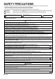
SAFETY PRECAUTIONS The original instructions are written in English. All other languages are translations of the original instructions. • Read these Safety Precautions carefully to ensure correct installation. • This manual classifies the precautions into WARNING and CAUTION. Be sure to follow all the precautions below: they are all important for ensuring safety. WARNING...............Failure to follow any of WARNING is likely to result in such grave consequences as death or serious injury. CAUTION ........
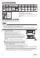
ACCESSORIES Clamp metal Insulation for fitting 1 pc. 1 each Washer for Drain hose hanging bracket Sealing pad Large and small 3 pcs. 1 each (only for 50-60 type) 1 pc. 1 pc. Sealing material Clamp 2 pcs. 6 pcs. 8 pcs. Washer Screws for fixing plate duct flanges 1 set 1 set 4 pcs. 24 pcs. 2 large for gas pipe Large 1 small for liquid pipe Stored in outlet vent Optional accessories Air fillter 1 pc.
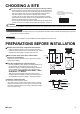
CHOOSING A SITE Select the signal receiver mounting location according to the following conditions: • Install the signal receiver, which has a built-in temperature sensor, near the intake vent where there is convection of air and it can get an accurate reading of the room’s temperature. If the intake vent is in another room or the unit cannot be installed near the intake vent for any other reason, install it 1.5m above the floor on a wall where there is convection.
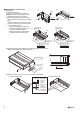
Mount chamber lid and air filter (accessory). In case of bottom suction. (1)Remove the chamber lid. (7 locations) (2)Reattach the removed chamber lid in the orientation shown in Fig.(7 locations) (3)Attach sealing pad as shown in the figure below. (Stored in outlet vent) (only for 50-60 type) (In order to take in the air inside the ceiling, and when not taking in air from outdoor air, it is not necessary to stick.
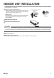
INDOOR UNIT INSTALLATION As for the parts to be used for installation work, be sure to use the provided accessories and specified parts designated by our company. Install the indoor unit temporarily. • Attach the hanger bracket to the suspension bolt. Be sure to fix it securely by using a nut and washer from the upper and lower sides of the hanger bracket. (Refer to Fig.
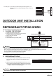
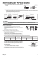
For heat pump: If your feet feel cold when using the heating function, it is recommended that the air discharge grille shown at below be attached. 45° (Adjustable angle) OUTDOOR UNIT INSTALLATION Install as described in the installation manual supplied with the outdoor unit. REFRIGERANT PIPING WORK See the installation manual supplied with the outdoor unit. 1. FLARING THE PIPE END 1) Cut the pipe end with a pipe cutter.
REFRIGERANT PIPING WORK 3) After the work is finished, make sure to check that there is no gas leak. Coat here with refrigeration machine oil Torque wrench Spanner Flare nut Piping union 4) After checking for gas leaks, be sure to insulate the pipe connections. • Insulate using the insulation for fitting included with the liquid and gas pipes. Besides, make sure the insulation for fitting on the liquid and gas piping has its seams facing up. (Tighten both edges with clamp.
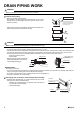
DRAIN PIPING WORK Caution Make sure all water is out before making the duct connection. Install the drain piping. Drain pipe connection hole • Make sure the drain works properly. • The diameter of the drain pipe should be greater than or equal to the diameter of the connecting pipe (vinyl tube; pipe size: 20mm; outer dimension: 26mm). Refrigerant pipes Connect the drain pipe after removing the rubber cap and insulation tubing attached to the connection hole.
INSTALLING THE DUCT Connect the duct supplied in the field. Air inlet side • Attach the duct and intake-side flange (field supply). • Connect the flange to the main unit with accessory screws (in 16, 20 or 24 positions). • Wrap the intake-side flange and duct connection area with aluminum tape or something similar to prevent air escaping. Caution When attaching a duct to the intake side, be sure also to attach an air filter inside the air passage on the intake side.
WIRING See the installation manual supplied with the outdoor unit. HOW TO CONNECT WIRINGS. • Wire only after removing the control box lid as shown in the Fig. Control box lid Power supply wiring Earth wire • Make sure to let a wire go through a wire penetration area. • After wiring, seal the wire and wire penetration area to prevent moisture and small creatures from the outside. • Wrap the strong and weak electric lines with the sealing material as shown in the figure below.
Warning Do not use tapped wires, stand wires, extensioncords, or starbust connections, as they may cause overheating, electrical shock, or fire. To outdoor unit When wire length exceeds 10m, use 2.0mm wires. Indoor unit 1 2 3 1.6mm or 2.0mm H07RN-F TRIAL OPERATION AND TESTING Trial operation and testing (1) Measure the supply voltage and make sure that it falls in the specified range. (2) Trial operation should be carried out in either cooling or heating mode.
WIRING DIAGRAM : FIELD WIRING : CONNECTOR : WIRE CLAMP : PROTECTIVE EARTH (SCREW) : LIVE : NEUTRAL L N BLK BLU BRN GRY ORG PNK : BLACK : BLUE : BROWN : GREY : ORANGE : PINK PRP RED WHT YLW GRN : PURPLE : RED : WHITE : YELLOW : GREEN INDOOR UNIT RECEIVER/DISPLAY UNIT A1P........................ PRINTED CIRCUIT BOARD A2P ........................PRINTED CIRCUIT BOARD C105...................... CAPACITOR A3P ........................PRINTED CIRCUIT BOARD PS..........................
4P325054-1 2012.