SiBE18 - 821 E-Series [Applied Models] Super Multi Plus : Heat Pump
SiBE18-821 SUPER MULTI PLUS E-Series zHeat Pump Indoor Unit FTXG25EV1BW(S) FTXG35EV1BW(S) CTXG50EV1BW(S) FTXS20G2V1B FTXS25G2V1B FTXS35G2V1B FTXS42G2V1B FTXS50G2V1B FTXS60FV1B FTXS71FV1B FDXS50CVMB FDXS60CVMB FDXS25EAVMB FDXS35EAVMB FVXS25FV1B FVXS35FV1B FVXS50FV1B FLXS25BAVMB FLXS35BAVMB FLXS50BAVMB FLXS60BAVMB FHQ35BVV1B FHQ50BVV1B FHQ60BVV1B FFQ25B8V1B FFQ35B8V1B FFQ50B8V1B FFQ60B8V1B Outdoor Unit RMXS112E8V1B RMXS140E8V1B RMXS160E8V1B Table of Contents BPMKS967B2B BPMKS967B3B i
SiBE18-821 1. Introduction ........................................................................................... vii 1.1 Safety Cautions ...................................................................................... vii 1.2 Used Icons .............................................................................................. xi Part 1 List of Functions ................................................................ 1 1. List of Functions ..................................................
SiBE18-821 3.3 3.4 3.5 3.6 Defrosting Operation ..............................................................................68 Pump-down Residual Operation ............................................................69 Restart Standby......................................................................................69 Stopping Operation ................................................................................70 4. Protection Control ............................................................
SiBE18-821 4.6 Centralized Group No. Setting .............................................................162 4.7 Maintenance Mode Setting...................................................................164 5. Test Operation and Field Setting for RA Indoor Unit...........................166 5.1 Test Operation from the Remote Controller .........................................166 5.2 Jumper Settings ...................................................................................
SiBE18-821 5.14 Malfunction of Field Setting Switch ......................................................291 5.15 Check ...................................................................................................292 6. Troubleshooting for BP Unit ................................................................294 6.1 6.2 6.3 6.4 6.5 6.6 Malfunction of Electronic Expansion Valve ..........................................294 Faulty BP Unit PCB .......................................................
SiBE18-821 7.36 System is not Set yet............................................................................344 7.37 Malfunction of System, Refrigerant System Address Undefined..........345 8. Check ..................................................................................................346 9. Thermistor Resistance / Temperature Characteristics........................349 10.Pressure Sensor .................................................................................351 11.
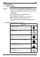
SiBE18-821 Introduction 1. Introduction 1.1 Safety Cautions Cautions and Warnings Be sure to read the following safety cautions before conducting repair work. The caution items are classified into “ Warning” and “ Caution”. The “ Warning” items are especially important since they can lead to death or serious injury if they are not followed closely. The “ Caution” items can also lead to serious accidents under some conditions if they are not followed.
Introduction SiBE18-821 Warning Be sure to wear a safety helmet, gloves, and a safety belt when working at a high place (more than 2m). Insufficient safety measures may cause a fall accident. In case of R410A refrigerant models, be sure to use pipes, flare nuts and tools for the exclusive use of the R410A refrigerant. The use of materials for R22 refrigerant models may cause a serious accident such as a damage of refrigerant cycle as well as an equipment failure.
SiBE18-821 Introduction 1.1.2 Cautions Regarding Safety of Users Warning Be sure to use parts listed in the service parts list of the applicable model and appropriate tools to conduct repair work. Never attempt to modify the equipment. The use of inappropriate parts or tools may cause an electrical shock, excessive heat generation or fire. If the power cable and lead wires have scratches or deteriorated, be sure to replace them.
Introduction SiBE18-821 Warning Check to make sure that the power cable plug is not dirty or loose, then insert the plug into a power outlet securely. If the plug has dust or loose connection, it may cause an electrical shock or fire. Be sure to install the product correctly by using the provided standard For unitary type installation frame. only Incorrect use of the installation frame and improper installation may cause the equipment to fall, resulting in injury.
SiBE18-821 Introduction Caution Be sure to measure the insulation resistance after the repair, and make sure that the resistance is 1 MΩ or higher. Faulty insulation may cause an electrical shock. Be sure to check the drainage of the indoor unit after the repair. Faulty drainage may cause the water to enter the room and wet the furniture and floor. Do not tilt the unit when removing it. The water inside the unit may spill and wet the furniture and floor.
Introduction xii SiBE18-821
SiBE18-821 Part 1 List of Functions 1. List of Functions ......................................................................................
List of Functions SiBE18-821 Basic Function Compressor Comfortable Airflow Comfort Control Operation Lifestyle Convenience Functions Inverter (with Inverter Power Control) { Operation Limit for Cooling (°CDB) –5 ~ 46 Operation Limit for Heating (°CWB) –15 ~ 15.5 Category Health & Clean RMXS112/140/160E8V1B Category RMXS112/140/160E8V1B 1.
Comfortable Airflow Comfort Control Operation Lifestyle Convenience CTXG50EV1BW(S) FTXS20-50G2V1B Air Purifying Filter — — — — Photocatalytic Deodorizing Filter — — — — Air Purifying Filter with Photocatalytic Deodorizing Function — — — Inverter (with Inverter Power Control) { { { Operation Limit for Cooling (°CDB) — — — Operation Limit for Heating (°CWB) — — PAM Control Compressor FTXG25/35EV1BW(S) Basic Function Functions FTXS20-50G2V1B Category CTXG50EV1BW(S) List o
Basic Function Compressor Comfortable Airflow Comfort Control Operation Lifestyle Convenience Functions Inverter (with Inverter Power Control) { Operation Limit for Cooling (°CDB) — Operation Limit for Heating (°CWB) — PAM Control — Standby Electricity Saving — Category Health & Clean FTXS60/71FV1B Category SiBE18-821 FTXS60/71FV1B List of Functions Functions Air Purifying Filter — Photocatalytic Deodorizing Filter — Air Purifying Filter with Photocatalytic Deodorizing Function
Inverter (with Inverter Power Control) { { Operation Limit for Cooling (°CDB) — — Operation Limit for Heating (°CWB) Compressor Comfortable Airflow Comfort Control Operation Lifestyle Convenience — — — Standby Electricity Saving — — Air Purifying Filter — — Photocatalytic Deodorizing Filter — — Air Purifying Filter with Photocatalytic Deodorizing Function — — Titanium Apatite Photocatalytic Air-Purifying Filter — — Category Health & Clean — PAM Control FDXS25/35EAVMB Basic
{ { Operation Limit for Cooling (°CDB) — — Operation Limit for Heating (°CWB) Compressor Comfortable Airflow Comfort Control Operation Lifestyle Convenience — FVXS25-50FV1B FVXS25-50FV1B Inverter (with Inverter Power Control) FLXS25-60BAVMB Functions Category Basic Function SiBE18-821 FLXS25-60BAVMB List of Functions Air Purifying Filter { — Category Health & Clean Functions Photocatalytic Deodorizing Filter { — — Air Purifying Filter with Photocatalytic Deodorizing Function
Inverter (with Inverter Power Control) { { Operation Limit for Cooling (°CDB) — — Operation Limit for Heating (°CWB) Compressor Comfortable Airflow Comfort Control Operation Lifestyle Convenience — FHQ35-60BVV1B Basic Function Functions FFQ25-60B8V1B Category FHQ35-60BVV1B List of Functions FFQ25-60B8V1B SiBE18-821 Air Purifying Filter — — Photocatalytic Deodorizing Filter — — Air Purifying Filter with Photocatalytic Deodorizing Function — — Category Health & Clean — Functi
List of Functions 8 SiBE18-821 List of Functions
SiBE18-821 Part 2 Specifications 1. Specifications ........................................................................................10 1.1 Outdoor Units .........................................................................................10 1.2 BP Unit ...................................................................................................11 1.3 Indoor Units ............................................................................................
Specifications SiBE18-821 1. Specifications 1.1 Outdoor Units 50Hz 230V Model RMXS112E8V1B Cooling Capacity Heating Capacity EER COP kW kW Cooling Heating Max. Total Indoor Unit Capacity Index Min. Total Indoor Unit Capacity Index Power Consumption W Running Current A RMXS140E8V1B 4HP 5HP 6HP 11.2 12.5 14.0 16.0 15.5 17.5 3.20 2.75 2.87 3.18 3.07 3.22 130 50 162.5 62.
SiBE18-821 1.2 Specifications BP Unit 50Hz 230V Model BPMKS967B2B Connectable Indoor Units BPMKS967B3B 1~2 Units 1~3 Units Casing Color Paintingless Power Consumption W 10 10 Running Current Refrigerant Type A 0.05 0.05 R-410A Dimension (H×W×D) Package Dimension (H×W×D) mm mm 180×294(650)*×350 257×738×427 Machine Weight kg 7.5 8 Gross Weight kg 11 12 mm Main : φ9.5×1 / Branch : φ6.4×2 Main : φ9.5×1 / Branch : φ6.4×3 mm Main : φ19.1×1 / Branch : φ15.9×2 Main : φ19.
Specifications 1.3 SiBE18-821 Indoor Units Wall Mounted Type 50Hz 230V FTXG25EV1BW Model Cooling Rated Capacity Front Panel Color Airflow Rates m³/min (cfm) Type Motor Output Speed Air Direction Control Air Filter Running Current (Rated) Power Consumption (Rated) Power Factor Temperature Control Dimensions (H×W×D) Packaged Dimensions (H×W×D) Weight Gross Weight Operation H/M/L/SL Sound Sound Power H Heat Insulation Liquid Piping Connection Gas Drain Drawing No.
SiBE18-821 Specifications 50Hz 230V CTXG50EV1BW Model Cooling Rated Capacity Front Panel Color Airflow Rates m³/min (cfm) Type Motor Output Speed Air Direction Control Air Filter Running Current (Rated) Power Consumption (Rated) Power Factor Temperature Control Dimensions (H×W×D) Packaged Dimensions (H×W×D) Weight Gross Weight Operation H/M/L/SL Sound Sound Power H Heat Insulation Liquid Piping Connection Gas Drain Drawing No. H M L SL W Steps A W % mm mm kg kg 11.3 (398) 9.1 (320) 7.1 (250) 6.
Specifications SiBE18-821 50Hz 230V FTXS35G2V1B Model Cooling Rated Capacity Front Panel Color Airflow Rates m³/min (cfm) Type Motor Output Speed Air Direction Control Air Filter Running Current (Rated) Power Consumption (Rated) Power Factor Temperature Control Dimensions (H×W×D) Packaged Dimensions (H×W×D) Weight Gross Weight Operation H/M/L/SL Sound Sound Power H Heat Insulation Liquid Piping Connection Gas Drain Drawing No. H M L SL W Steps A W % mm mm kg kg 10.7 (367) 7.7 (270) 4.8 (170) 3.
SiBE18-821 Specifications 50Hz 230V FTXS60FV1B Model Cooling Rated Capacity Front Panel Color Airflow Rates Cooling 6.0kW Class White m³/min (cfm) Type Motor Output Speed Air Direction Control Air Filter Running Current (Rated) Power Consumption (Rated) Power Factor Temperature Control Dimensions (H×W×D) Packaged Dimensions (H×W×D) Weight Gross Weight Operation H/M/L/SL Sound Sound Power H Heat Insulation Liquid Piping Connection Gas Drain Drawing No.
Specifications SiBE18-821 Duct Connected Type 50Hz 230V FDXS50CVMB Model Cooling Rated Capacity Front Panel Color m³/min (cfm) Type Motor Output Speed H M L SL W Steps A W % mm mm kg kg dBA Pa mm mm mm 12.0 (424) 11.0 (388) 10.0 (353) 8.4 (297) — 12.0 (424) 11.0 (388) 10.0 (353) 8.4 (297) Sirocco Fan 130 5 Steps, Quiet, Auto Removable-Washable-Mildew Proof 0.64 0.64 140 140 95.1 95.1 Microcomputer Control 200×900×620 266×1,106×751 27 34 37/35/33/31 37/35/33/31 40 Both Liquid and Gas Pipes φ 6.
SiBE18-821 Specifications Floor / Ceiling Suspended Dual Type 50Hz 230V FLXS25BAVMB Model Cooling Rated Capacity Front Panel Color Airflow Rates m³/min (cfm) Type Motor Output Speed Air Direction Control Air Filter Running Current (Rated) Power Consumption (Rated) Power Factor Temperature Control Dimensions (H×W×D) Packaged Dimensions (H×W×D) Weight Gross Weight Operation H/M/L/SL Sound Sound Power H Heat Insulation Liquid Piping Connection Gas Drain Drawing No.
Specifications SiBE18-821 Floor Standing Type 50Hz 230V FVXS25FV1B Model Cooling Rated Capacity Front Panel Color Airflow Rates Heating Type Motor Output Speed Air Direction Control Air Filter Running Current (Rated) Power Consumption (Rated) Power Factor Temperature Control Dimensions (H×W×D) Packaged Dimensions (H×W×D) Weight Gross Weight Operation H/M/L/SL Sound Sound Power H Heat Insulation Liquid Piping Connection Gas Drain Drawing No. Fan H M L SL W Steps A W % 8.2 (290) 6.5 (229) 4.
SiBE18-821 Specifications Ceiling Mounted Cassette Type 50Hz 230V FFQ25B8V1B Model Cooling Rated Capacity Color Decoration Panel Dimensions (H×W×D) Airflow Rates m³/min (cfm) Type Fan Motor Output Speed Air Direction Control Air Filter Cooling 2.5kW Class White 55×700×700 H M L SL 9.0 (318) 10.0 (353) — — — — 6.5 (230) 6.5 (230) 6.5 (230) 6.5 (230) — — — — Turbo Fan 55 2 Steps Horizontal, Downward dBA dBA mm mm mm — 0.37 73 85.8 0.32 64 87.0 0.40 84 91.
Specifications SiBE18-821 Ceiling-suspended Type 50Hz 230V Model Rated Capacity Color Decoration Panel Dimensions (H×W×D) Airflow Rates m³/min (cfm) Type Motor Output Speed Air Direction Control Air Filter Temperature Control Dimensions (H×W×D) Packaged Dimensions (H×W×D) Weight Gross Weight Operation H/L Sound Sound Power H/L Heat Insulation Liquid Piping Connection Gas Drain Drawing No. Fan H M L SL W Steps mm mm kg kg FHQ35BVV1B Cooling Heating 3.5kW Class White — 13.0 (458) 13.0 (458) — 10.
SiBE18-821 Part 3 Printed Circuit Board Connector Wiring Diagram 1. Printed Circuit Board Connector Wiring Diagram ............................................22 1.1 1.2 1.3 1.4 1.5 1.6 1.7 1.8 1.9 1.10 Outdoor Unit RMXS 112/140/160 E8V1B ..............................................22 Branch Provider Unit ..............................................................................27 FTXG25~35E, CTXG50E .......................................................................
Printed Circuit Board Connector Wiring Diagram SiBE18-821 1. Printed Circuit Board Connector Wiring Diagram 1.1 Outdoor Unit RMXS 112/140/160 E8V1B 1.1.
SiBE18-821 PCB Detail Printed Circuit Board Connector Wiring Diagram Main PCB (A1P) X106A X107A F6U P X111A X66A N X37A X81A X5A X22A LE X21A X13A X11A X12A NC X18A X17A X32A LC HAP X25A X26A X27A X28A LD F4U 2P210453 Printed Circuit Board Connector Wiring Diagram 23
Printed Circuit Board Connector Wiring Diagram SiBE18-821 1.1.
SiBE18-821 Printed Circuit Board Connector Wiring Diagram 1.1.3 Noise Filter PCB (A3P) Connectors 1) LA, NA 2) LB, NB 3) E Note: PCB Detail Terminal for X1M (Power Supply) Terminal for Main PCB (A1P) Terminal for Earth Other Designation 1) F1U Fuse (250V 6.
Printed Circuit Board Connector Wiring Diagram SiBE18-821 1.1.
SiBE18-821 1.2 Printed Circuit Board Connector Wiring Diagram Branch Provider Unit Connectors 1) X20A 2) X21A to X23A 3) X90A Note: Connector for Bypass Electronic Expansion Valve Connector for Electronic Expansion Valve to Room A, B and C Connector for Thermistors Other Designations 1) F2U 2) X3M 3) X4M 4) X5M 5) F1, F2 (on X6M) 6) L1, N1 (on X1M) 7) L2, N2 (on X1M) 8) H1P(LED-A) 9) H2P~H5P (LED 1 to 4) Fuse (AC250V 3.
Printed Circuit Board Connector Wiring Diagram 1.
SiBE18-821 PCB Detail Printed Circuit Board Connector Wiring Diagram PCB(1): Control PCB (indoor unit) S1 S49 S41 S51 JB JA JC LED A V1 S21 FU1 S46 S36 S32 (R4991) PCB(2): Signal Receiver PCB S47 RTH1 SW1 LED4 LED2 LED3 (R4992) PCB(3): INTELLIGENT EYE sensor PCB S36 (R4988) Printed Circuit Board Connector Wiring Diagram 29
Printed Circuit Board Connector Wiring Diagram 1.
SiBE18-821 PCB Detail S41 Printed Circuit Board Connector Wiring Diagram PCB(1): Control PCB S1 S32 LED A FU1 S46 V1 S25 S47 JC JB S21 JA 2P206687 PCB(2): Signal Receiver PCB PCB(3): Display PCB RTH1 SW1 LED3 LED2 LED1 S48 (R8246) S49 (R8247) PCB(4): INTELLIGENT EYE sensor PCB S26 3EB86013 Printed Circuit Board Connector Wiring Diagram 31
Printed Circuit Board Connector Wiring Diagram 1.
SiBE18-821 PCB Detail Printed Circuit Board Connector Wiring Diagram PCB(1): Control PCB (indoor unit) S1 V1 FU1 S21 S6 S8 S35 LED A JA JB JC PCB(2): Signal Receiver PCB S32 S28 S26 (R2860) PCB(3): Buzzer PCB S27 SW1 S38 S29 (R2861) RTH1 PCB(4): Display PCB LED1 LED2 (R2862) PCB(5): INTELLIGENT EYE sensor PCB LED3 S37 (R2863) S36 (R2864) Printed Circuit Board Connector Wiring Diagram 33
Printed Circuit Board Connector Wiring Diagram 1.
SiBE18-821 PCB Detail Printed Circuit Board Connector Wiring Diagram PCB (2): Display PCB S1 LED3 WLU PbF LED2 RTH1 C3 C2 + C1 Pb Free SW1 LED1 2P084375 Printed Circuit Board Connector Wiring Diagram 35
Printed Circuit Board Connector Wiring Diagram 1.
SiBE18-821 Printed Circuit Board Connector Wiring Diagram PCB Detail PCB (1): Control PCB (indoor unit) PCB Detail PCB (2): Power Supply PCB Printed Circuit Board Connector Wiring Diagram 37
Printed Circuit Board Connector Wiring Diagram SiBE18-821 PCB (3): Display PCB PCB (4): Signal Receiver PCB SW1 EX511 REV 12 PbF S27 C1 3 SW1 C2 RTH I PHOTO 2P084377- 1 S31(RTH) 38 WLU C3 (R4977) Printed Circuit Board Connector Wiring Diagram
SiBE18-821 1.
Printed Circuit Board Connector Wiring Diagram PCB Detail 40 SiBE18-821 PCB (1): Power Supply PCB Printed Circuit Board Connector Wiring Diagram
SiBE18-821 PCB Detail Printed Circuit Board Connector Wiring Diagram PCB (2): Control PCB (indoor unit) PCB (3): Display PCB PCB (4): Signal Receiver PCB Printed Circuit Board Connector Wiring Diagram 41
Printed Circuit Board Connector Wiring Diagram 1.
SiBE18-821 PCB Detail Printed Circuit Board Connector Wiring Diagram PCB (1): Control PCB (A1P) X20A X25A X27A X33A X18A Capacity setting adaptor X19A X61A X40A EC0608(A) X36A X60A HAP (Service monitor LED) X17A X24A X35A X15A X5A 2P095006 Printed Circuit Board Connector Wiring Diagram 43
Printed Circuit Board Connector Wiring Diagram SiBE18-821 1.
SiBE18-821 PCB Detail Printed Circuit Board Connector Wiring Diagram Control PCB (A1P) X19A X18A Capacity setting adaptor X40A X15A X14A X17A X61A X35A X60A X33A X5A HAP (Service monitor LED) X24A X26A X25A X27A EC0606(A) X29A X20A 2P095007 Printed Circuit Board Connector Wiring Diagram 45
Printed Circuit Board Connector Wiring Diagram 46 SiBE18-821 Printed Circuit Board Connector Wiring Diagram
SiBE18-821 Part 4 Refrigerant Circuit 1. Refrigerant Circuit .................................................................................48 1.1 Outdoor Units .........................................................................................48 1.2 BP Units .................................................................................................50 2. Functional Parts Layout ........................................................................51 2.1 Outdoor Units ......................
Refrigerant Circuit SiBE18-821 1. Refrigerant Circuit 1.1 Outdoor Units No. in refrigerant Symbol system diagram 48 Name Major Function A M1C Inverter compressor (INV) Inverter compressor is operated on frequencies between 36 Hz and 195 Hz by using the inverter. 31 steps D M1F M2F Inverter fan Since the system is of air heat exchanging type, the fan is operated at 8-step rotation speed by using the inverter.
SiBE18-821 Refrigerant Circuit H F A O S T E P M D D N G Refrigerant Circuit Diagram C : 3D052627A Refrigerant Circuit 49
Refrigerant Circuit 1.2 SiBE18-821 BP Units No. in refrigerant Symbol system diagram Name Major Function A EVU Electronic expansion valve (for operating room) Among EVA, EVB and EVC, the electronic expansion valve of operating room is called EVU. B EVT Electronic expansion valve (for stopping room) Among EVA, EVB and EVC, the electronic expansion valve of stopping room is called EVT.
SiBE18-821 Functional Parts Layout 2. Functional Parts Layout 2.
SV SP FILTER SERVICE PORT ELECTRONIC EXPANSION VALVE : High pressure liquid refrigerant : High pressure high temp. gas refrigerant : Low pressure low temp.
Refrigerant Circuit SERVICE PORT SV SP FILTER ELECTRONIC EXPANSION VALVE PRESSURE REGULATING VALVE EV1 EV3 SVP PI control PI control OFF ELECTRONIC EXPANSION VALVE FILTER ACCUMULATOR CAPILLARY TUBE SERVICE PORT FILTER DOUBLE PIPE HEAT EXCHANGER LOW PRESSURE SENSOR : High pressure liquid refrigerant : High pressure high temp. gas refrigerant : Low pressure low temp.
SV SP FILTER SERVICE PORT ELECTRONIC EXPANSION VALVE PRESSURE REGULATING VALVE EV1 EV2 SVP 480 pls Full close OFF ELECTRONIC EXPANSION VALVE FILTER ACCUMULATOR CAPILLARY TUBE SERVICE PORT FILTER DOUBLE PIPE HEAT EXCHANGER LOW PRESSURE SENSOR : High pressure liquid refrigerant : High pressure high temp. gas refrigerant : Low pressure low temp.
Refrigerant Circuit SV SP FILTER SERVICE PORT CAPILLARY TUBE EV1 EV2 SVP 480 pls 55 pls OFF ELECTRONIC EXPANSION VALVE FILTER ACCUMULATOR CAPILLARY TUBE SERVICE PORT FILTER DOUBLE PIPE HEAT EXCHANGER LOW PRESSURE SENSOR PRESSURE REGULATING VALVE ELECTRONIC EXPANSION VALVE CAPILLARY TUBE COMPRESSOR FILTER SV SOLENOID VALVE HIGH PRESSURE SWITCH : High pressure liquid refrigerant : High pressure high temp. gas refrigerant : Low pressure low temp.
Refrigerant Flow for Each Operation Mode 56 SiBE18-821 Refrigerant Circuit
SiBE18-821 Part 5 Function 1. Operation Mode ....................................................................................58 2. Basic Control.........................................................................................59 2.1 2.2 2.3 2.4 Normal Operation ...................................................................................59 Compressor PI Control...........................................................................60 Electronic Expansion Valve PI Control...............
Operation Mode SiBE18-821 1.
SiBE18-821 Basic Control 2. Basic Control 2.1 Normal Operation Cooling Operation Actuator Operation Compressor Compressor PI control Outdoor unit fan Four way valve Main electronic expansion valve (EV1) Subcooling electronic expansion valve (EV3) Cooling fan control OFF 480 pls Remarks Used for high pressure protection control, low pressure protection control, discharge pipe temperature protection control, and compressor operating frequency upper limit control with inverter protection control.
Basic Control 2.2 SiBE18-821 Compressor PI Control Compressor PI Control Carries out the compressor capacity PI control to maintain Te at constant during cooling operation and Tc at constant during heating operation to ensure stable unit performance. [Cooling operation] Controls compressor capacity to adjust Te to achieve target value (TeS).
SiBE18-821 ∆D Control Basic Control Receiving the capacity request signal from the indoor unit, the outdoor unit corrects its target pressure for capacity control. Controls ∆D signal from indoor unit as follows. UP control : When the UP command come from more than one indoor unit among thermostat-ON indoor units. Down control : When the down command come from all indoor units among thermostat-ON indoor units.
Basic Control SiBE18-821 Heating Operation TcS = TcS initial value + KTc2 KTc2 : Correction value by ∆D signal in heating. KTc2 = 0 (without correction) During compressor frequency PI control (KTc2 = 0) Not during compressor frequency PI control ∆ D control Keep the current KTc2 KTc2 = KTc2 + 0.5 Up control by ∆ D signal continues 120 sec. KTc2 = KTc2 - 0.5 Down control by ∆ D signal continues 120 sec.
SiBE18-821 2.3 Basic Control Electronic Expansion Valve PI Control Main Electronic Expansion Valve EV1 Control Carries out the electronic expansion valve (Y1E) PI control to maintain the evaporator outlet superheated degree (SH) at constant during heating operation to make maximum use of the outdoor unit heat exchanger (evaporator).
Basic Control 2.4 SiBE18-821 Cooling Operation Fan Control In cooling operation with low outdoor air temperature, this control is used to provide the adequate amount of circulation air with liquid pressure secured by high pressure control using outdoor unit fan. Furthermore, when outdoor temperature ≥ 20°C, the compressor will run in Step 7 or higher. When outdoor temperature ≥ 18°C, it will run in Step 5 or higher. When outdoor temperature ≥ 12°C, it will run in Step 1 or higher.
SiBE18-821 Special Control 3. Special Control 3.1 Startup Control This control is used to equalize the pressure in the front and back of the compressor prior to the startup of the compressor, thus reducing startup loads. Furthermore, the inverter is turned ON to charge the capacitor. In addition, to avoid stresses to the compressor due to oil return or else after the startup, the following control is made and the position of the four way valve is also determined.
Special Control 3.2 SiBE18-821 Oil Return Operation Oil flown from the compressor to the side of system is collected by oil-returning operation, in case of that oil in the compressor runs down. 3.2.1 Oil Return Operation in Cooling Operation [Conditions to start] The cooling oil-returning operation is started referring following conditions. Integrated amount of displaced oil Timer (After the power is turned on, integrated operating-time is 2 hours and subsequently every 8 hours.
SiBE18-821 Special Control 3.2.2 Oil Return Operation in Heating Operation [Conditions to start] The heating oil-returning operation is started referring following conditions. Integrated amount of displaced oil Timer (After the power is turned on, integrated operating-time is 2 hours and subsequently every 8 hours.) In addition, integrated amount of displaced oil is derived from Tc, Te, and the compressor load.
Special Control 3.3 SiBE18-821 Defrosting Operation The defrost operation is performed to solve frost on the outdoor unit heat exchanger when heating, and the heating capacity is recovered. [Conditions to start] The defrost operation is started referring following conditions.
SiBE18-821 3.4 Special Control Pump-down Residual Operation When activating compressor, if the liquid refrigerant remains in the heat-exchanger, the liquid enters into the compressor and dilutes oil therein resulting in decrease of lubricity. Therefore, the pump-down residual operation is performed to collect the refrigerant in the heatexchanger when the compressor is down. 3.4.
Special Control 3.6 SiBE18-821 Stopping Operation Operation of the actuator when the system is down, is cleared up. 3.6.1 When System is in Stop Mode Actuator Operation Compressor OFF Outdoor unit fan OFF Four way valve Keep former condition. Main electronic expansion valve (EV1) 0 pls Subcooling electronic expansion valve (EV3) 0 pls Hot gas bypass valve (SVP) OFF Ending conditions Indoor unit thermostat is turned ON.
SiBE18-821 Protection Control 4. Protection Control 4.1 High Pressure Protection Control This high pressure protection control is used to prevent the activation of protection devices due to abnormal increase of high pressure and to protect compressors against the transient increase of high pressure. [In cooling operation] Pc>3.
Protection Control 4.2 SiBE18-821 Low Pressure Protection Control This low pressure protection control is used to protect compressors against the transient decrease of low pressure. [In cooling operation] Low pressure not limited Pe<0.25MPa Pe: LP pressure sensor detection value Pe>0.39MPa Low pressure limited Hot gas SVP = OFF Pe<0.15MPa Pe>0.30MPa 36Hz Unload Hot gas SVP = ON Pe<0.07MPa Low pressure standby When occurring 3 times within 30 min., the malfunction code "E4" is output.
SiBE18-821 4.3 Protection Control Discharge Pipe Protection Control This discharge pipe protection control is used to protect the compressor internal temperature against a malfunction or transient increase of discharge pipe temperature.
Protection Control 4.4 SiBE18-821 Inverter Protection Control Inverter current protection control and inverter fin temperature control are performed to prevent tripping due to a malfunction, or transient inverter overcurrent, and fin temperature increase. [Inverter overcurrent protection control] Not limited & Inverter current >23.8A •Inverter current ≤ 23.8A •INV upper limit frequency=max Hz Limited INV upper limit frequency: 1-step down from current compressor frequency •10 sec.
SiBE18-821 4.5 Protection Control Freeze-up Protection Control Outline According to the freeze prevention status sent from the BP unit. The compressor output frequency is regulated to decrease the compressor capacity in order to prevent the indoor heat exchanger from freezing. Detail Zones are produced based on the freeze prevention status signal sent from the BP unit (Indoor unit), and the freeze prevention control prevents freezing of the indoor unit.
Protection Control 4.6 SiBE18-821 Dew Condensation Prevention Control Outline According to the dew condensation prevention status sent from the BP unit. The compressor output frequency is regulated to decrease the compressor capacity in order to prevent the indoor unit from dew condensation. Detail Zones are produced based on the dew condensation prevention status signal sent from the BP unit (Indoor unit), and the dew condensation prevention control prevents dew condensation of the indoor unit.
SiBE18-821 Other Control 5. Other Control 5.1 Demand Operation In order to save the power consumption, the capacity of outdoor unit is saved with control forcibly by using “Demand 1 Setting”. To operate the unit with this mode, additional setting of “Continuous Demand Setting” or external input by external control adaptor is required. [Demand 1 setting] Setting Demand 1 setting 1 Standard for upper limit of power consumption Approx. 60% Demand 1 setting 2 (factory setting) Demand 1 setting 3 5.
BP Unit Control SiBE18-821 6. BP Unit Control 6.1 BP Unit Command Conversion 1. ∆D (room temperature − temperature setting) signals from BP units are converted to capacity up / down signal. ∆D signals from BP units are used as the capacity up / down signal in frequency commands (excludes when Powerful function is in operation). ∆D Signal Capacity up / down signal 0 1 Thermostat OFF 2 3 4 5 Down Keep 6 7 8 9 A B Up C D E F 2.
SiBE18-821 6.2 BP Unit Control BP Unit Electronic Expansion Valve Control Purpose of the Function This function provides instructions regarding the absolute flow rate, relative flow rate and fully closing from the outdoor unit to the BP unit in order to ensure outdoor unit compressor safety and optimum refrigerating cycle of the system. With the transmission a permit/prohibit flag for each distribution control in the BP unit, the distribution control startup timing is controlled by the outdoor unit.
BP Unit Control SiBE18-821 6.2.3 Full Closing of Electronic Expansion Valves Purpose of the Function The electronic expansion valves are initialized when the power is turned on. Details The following processes are conducted. 1. Conducts P1 pulses close when power is turned on, and sets current opening to 0 pulse (fully closing process). 2. Sends electronic expansion valve initialization signal to outdoor unit. 3.
SiBE18-821 6.3 BP Unit Control SH Control in Cooling Operation Purpose of the Function This function ensures appropriate refrigerant distribution when many room units are operating in the cooling mode.
BP Unit Control Note: 6.4 SiBE18-821 1. In Sky Air models, the indoor units are equipped with distribution capillary tubes ; therefore, the heat exchangers may superheat even when the condition is met. 2. In Sky Air models, the heat exchanger intermediate position is provided on the liquid connection pipe side; as a result, superheated condition is difficult to detect.
SiBE18-821 Indoor Unit (RA Models) 7. Indoor Unit (RA Models) 7.1 Power-Airflow Dual Flaps, Wide Angle Louvers and Auto-Swing Power-airflow Dual Flaps The large flaps send a large volume of air downwards to the floor. The flap provides an optimum control area in cooling, heating and dry mode. Heating Mode During heating mode, the large flap enables direct warm air straight downwards. The flap presses the warm air above the floor to reach the entire room.
Indoor Unit (RA Models) COMFORT AIRFLOW Mode SiBE18-821 FTXS20-50G The vertical swing flap is controlled not to blow the air directly on the person in the room. The airflow rate is controlled automatically within the following steps. Cooling: L tap – MH tap (same as AUTOMATIC) Heating: Equivalent to ML tap – MH tap The latest command has the priority between POWERFUL and COMFORT AIRFLOW.
SiBE18-821 7.2 Indoor Unit (RA Models) Fan Speed Control for Indoor Units Control Mode The airflow rate can be automatically controlled depending on the difference between the set temperature and the room temperature. This is done through phase control and Hall IC control. For more information about Hall IC, refer to the troubleshooting for fan motor on page 268. Phase Steps Phase control and fan speed control contains 9 steps: LLL, LL, SL, L, ML, M, MH, H and HH.
Indoor Unit (RA Models) 7.3 SiBE18-821 Programme Dry Function Programme dry function removes humidity while preventing the room temperature from lowering. Since the microcomputer controls both the temperature and airflow volume, the temperature adjustment and fan adjustment buttons are inoperable in this mode. In Case of Inverter Units The microcomputer automatically sets the temperature and fan settings.
SiBE18-821 7.4 Indoor Unit (RA Models) Automatic Operation Automatic Cooling / Heating Function (Heat Pump Only) When the AUTO mode is selected with the remote controller, the microcomputer automatically determines the operation mode from cooling and heating according to the room temperature and setting temperature at the time of the operation startup, and automatically operates in that mode.
Indoor Unit (RA Models) 7.5 SiBE18-821 Thermostat Control Thermostat control is based on the difference between the room temperature and the setpoint. Thermostat OFF Condition The temperature difference is in the zone A. Thermostat ON Condition The temperature difference is above the zone C after being in the zone A. The system resumes from defrost control in any zones except A. The operation turns on in any zones except A.
SiBE18-821 7.6 Indoor Unit (RA Models) Night Set Mode When the OFF timer is set, the Night Set circuit automatically activates. The Night Set circuit maintains the airflow setting made by users. The Night Set Circuit The Night Set circuit continues heating or cooling the room at the set temperature for the first one hour, then automatically raises the temperature setting slightly in the case of cooling, or lowers it slightly in the case of heating, for economical operations.
Indoor Unit (RA Models) 7.7 Outline SiBE18-821 ECONO Mode FTXS20-50G, FVXS25-50F The "ECONO mode" reduces the maximum operating current and power consumption by approx. 30% during start up etc.. This mode is particularly convenient for energy-saving-oriented users. It is also a major bonus for those whose breaker capacities do not allow the use of multiple electrical devices and air conditioners. It is easily activated from the wireless remote controller by pushing the ECONO button.
SiBE18-821 7.8 Indoor Unit (RA Models) INTELLIGENT EYE (FTXS-F) This is the function that detects existence of humans in the room by a human motion sensor (INTELLIGENT EYE) and reduces the capacity when there is no human in the room in order to save electricity. Processing 1. Detection method by INTELLIGENT EYE sampling (20msec) Sensor output 1sec If the sensor detects the outputs 10 times/sec. or more, it judges humans exist.
Indoor Unit (RA Models) SiBE18-821 Since the set temperature is shifted by 2°C higher for 40 minutes, compressor speed becomes low and can realize energy saving operation. But as thermostat is prone to be off by the fact that the set temperature has been shifted, the thermostat-off action is prohibited in 40 minutes so as to prevent this phenomena.
SiBE18-821 7.9 Indoor Unit (RA Models) 2 AREA INTELLIGENT EYE (FTXS-G) The following functions can be performed by a human motion sensor (INTELLIGENT EYE). 1. Reduces the capacity when there is no human in the room in order to save electricity. (energy saving operation) 2. Divides the room into plural areas and detects existence of humans in each area. Shifts the airflow direction to the area having no human automatically to avoid direct airflow on humans. Processing 1.
Indoor Unit (RA Models) SiBE18-821 2. The motions in energy saving operation (for example: in cooling) within 20 minutes. Human detection ON signal OFF (From area A or B) 20 min. 20 min. RESET. Cooling : Set temp. + 2˚C Heating : Set temp. - 2˚C Set temp.
SiBE18-821 Indoor Unit (RA Models) 7.10 HOME LEAVE Operation Outline In order to respond to the customer's need for immediate heating and cooling of the room after returning home or for house care, a measure to switch the temperature and air volume from that for normal time over to outing time by one touch is provided. (This function responds also to the need for keeping up with weak cooling or heating.
Indoor Unit (RA Models) Others 96 SiBE18-821 The set temperature and set air volume are memorized in the remote controller. When the remote controller is reset due to replacement of battery, it is necessary to set the temperature and air volume again for [HOME LEAVE].
SiBE18-821 Indoor Unit (RA Models) 7.11 Inverter POWERFUL Operation Outline In order to exploit the cooling and heating capacity to full extent, operate the air conditioner by increasing the indoor fan rotating speed and the compressor frequency. Details of the Control When POWERFUL button is pushed in each operation mode, the fan speed / setting temperature will be converted to the following states in a period of 20 minutes.
Indoor Unit (RA Models) SiBE18-821 7.12 Other Functions 7.12.1 Hot Start Function Heat Pump Only In order to prevent the cold air blast that normally comes when heating is started, the temperature of the heat exchanger of the indoor unit is detected, and either the airflow is stopped or is made very weak thereby carrying out comfortable heating of the room. *The cold air blast is also prevented using a similar control when the defrosting operation is started or when the thermostat gets turned ON. 7.12.
SiBE18-821 Indoor Unit (RA Models) 7.12.5 Photocatalytic Deodorizing Filter FLXS25-60B Photocatalytic Deodorizing Filter demonstrates powerful oxidation characteristics when subjected to harmless ultraviolet light. Photocatalytic deodorizing power is recovered simply by exposing the filter to the sun for 6 hours once every 6 months. 7.12.
Indoor Unit (SkyAir Models) SiBE18-821 8. Indoor Unit (SkyAir Models) 8.1 Function Outline FFQ-B, FHQ-B (Input) Indoor Unit (Output) Thermostat Control Suction Sensor(R1T) Two thermostats used, suction and remote controller.
SiBE18-821 8.
Indoor Unit (SkyAir Models) 8.3 SiBE18-821 Function Details Thermostat Control Freeze-up Protection Control 102 The thermostat turns OFF under the following temperature conditions to prevent freezing of the indoor unit heat exchanger. The motorized valve is controlled to maintain the indoor unit heat exchanger temperature (Te) above 0°C. The outdoor unit fan speed is reduced to prevent freeze-up protection control from activating during cooling operation under low outside air temperature.
SiBE18-821 Indoor Unit (SkyAir Models) Condensation Avoidance Control (FHQ Only) Continuous 30 minutes operation of cooling After continuous 30 minutes of operation with downward horizontal blade position, change the blade position to level, and after one hour, the unit operation can be reset. One hour drying The unit operation can be reset with changing operation mode into "heating" , changing air flow direction or turning "ON" or "OFF" the unit operation.
Indoor Unit (SkyAir Models) SiBE18-821 1-2 Operations when an occurrence of water level abnormality 1-2-a) Behavior between occurrence and recovery of water level abnormality After compressor stops due to water level abnormality, drain pump is operated intermittently, i.e. 5 min ON, 5 sec OFF and 5 min ON. (*1) The intermittent operation is executed regardless of recovery of water level abnormality during the intermittent operation.
SiBE18-821 Indoor Unit (SkyAir Models) 1-2-b) Behavior when the unit restarts by remote controller after the water level abnormality is recovered Water level abnormality shall be cancelled simultaneausly when the unit is turned off with remote controller after recovery of the water level abnormality. When the unit is turned on with remote controller thereafter, compressor starts operation 2 minutes later from the remote controller ON.
Indoor Unit (SkyAir Models) SiBE18-821 2. Heating 2-1 Basic operation In heating operation of the unit equipped with a humidifier, when "Interlocking of drain pump / humidifier" (15(25)-3) is set to "yes" (02), the drain pump operates 20-min OFF and 3-min ON repeatedly during compressor is in operation. After compressor stops, residual operation will be conducted for 5 minutes.
SiBE18-821 Indoor Unit (SkyAir Models) 2-2-a)-1 When a water level abnormality occurs during drain pump ON 1 The same operation as 1-2-a) "Behavior between occurrence and recovery of drain water level abnormality" in the mode of cooling or dry.
Indoor Unit (SkyAir Models) SiBE18-821 2-2-a)-2 When a water level abnormality occurs during drain pump OFF The abnormality is determined when 80 seconds elapse from compressor stop. Other than above, behavior is same as 2-2-a).
SiBE18-821 Using Conditions for Remote Controller Thermostat Function Indoor Unit (SkyAir Models) (Applicable models: FHQ & FFQ only) Remote controller thermostat is equipped only in wired remote controller. Even when “use remote controller thermostat” is selected in service mode, the remote controller thermostat may not be used. < Conditions not to use > 1. When the remote controller thermostat malfunctions. 2. When the one remote controller group control is applied.
Indoor Unit (SkyAir Models) Program Dry Operation Function SiBE18-821 The points of thermostat ON or OFF are determined according to the suction air temperature at the startup of unit operation. The set temperature and flow rate are not displayed on remote controller. Suction air temp. Ts Operation startup Thermostat ON (Differential) Thermostat OFF (S1120) 1. Thermostat ON point (TON) according to suction air temp. (TS). Suction air temp Ts>24°C 24°C≥ Ts>16°C 16°C≥ Ts TON(°C) Ts Ts 16°C TdON(°C) 1.
SiBE18-821 Indoor Unit (SkyAir Models) Fan and Flap Operations Heating Operation Flap FHQ & FFQ OFF Horizontal Remote Controller Indication Swing In Airflow Direction Setting In Swing Operation OFF Horizontal Set Position OFF Horizontal Swing In Airflow Direction Setting In Swing Operation OFF Horizontal Set Position LL Horizontal Swing In Airflow Direction Setting In Swing Operation LL Horizontal Set Position LL Horizontal Swing In Airflow Direction Setting In Swing Operation L
Indoor Unit (SkyAir Models) Mode Conflict SiBE18-821 [Overview] While the indoor unit for another room and the outdoor unit are operating, when the indoor unit for the own room is activated, the operation mode which can be selected in the own room has some restrictions as mentioned below. i) In case an priority for operation mode selection is given to the own room by setting the dip switch of outdoor unit; →The own room can be operated in any mode.
SiBE18-821 Non-operating Room Dew Prevention Fan Control Indoor Unit (SkyAir Models) [Overview] After operating an indoor unit for the own room in the cooling mode or dry mode, stop the unit using the remote controller. Under the condition, when an unit for another room is started operation in the heating mode, the fan in the own room may rotate in the LL mode even though the remote controller of the fan is in stop mode.
Indoor Unit (SkyAir Models) 114 SiBE18-821 Function
SiBE18-821 Part 6 Test Operation 1. Test Operation ....................................................................................116 1.1 Procedure and Outline .........................................................................116 2. Outdoor Unit PCB Layout....................................................................132 3. Field Setting ........................................................................................133 3.1 Field Setting from Outdoor Unit..........................
Test Operation SiBE18-821 1. Test Operation 1.1 Procedure and Outline Follow the following procedure to conduct the initial test operation after installation. 1.1.1 Check work prior to turn power supply on Check the below items.
SiBE18-821 Test Operation 1.1.3 Judging and reprogramming in case of redundant BP addresses The BP unit of this system is provided with specific addresses in its production stage. These addresses are used to conduct various controls. If by any chance (on 3 out of 260000 units) these addresses are redundant, the system may get in trouble. When replacing the PCB of the BP unit too, these addresses may be used repeatedly.
Test Operation SiBE18-821 Example of DIP switch (DS2) settings on the BP unit's PCB BP unit 1 DS2-1 OFF DS2-2 OFF DS2-3 ON DS2-4 OFF BP unit 2 BP unit 3 OFF OFF OFF OFF OFF ON ON ON DS1~4 : Factory setting is OFF. The BP unit 1 through 3 show the first through third unit, respectively. The order of these units is flexible. The above table is just for your reference. The redundancy of addresses can be avoided when the DIP switch settings are individually specified.
SiBE18-821 Test Operation 1.1.6 When the No. of Indoor Unit Has Been Changed, or Indoor (BP) or Outdoor Unit PC Board Has Been Changed, or the System is transferred Be sure to push and hold the RESET button for 5 seconds. If not, the addition cannot be recognized. In this case, the unit cannot be run for up to 12 minutes to automatically set the address (indoor-outdoor address, etc.) Status Outdoor unit Test lamp H2P .... ON Can also be set during operation described above.
Test Operation SiBE18-821 1.1.8 Additional Refrigerant Charge Caution ♦ Refrigerant cannot be charged until field wiring has been completed. ♦ Refrigerant may only be charged after performing the leak test and the vacuum drying (see above). ♦ When charging a system, care shall be taken that its maximum permissible charge is never exceeded, in view of the danger of liquid hammer.
SiBE18-821 Test Operation To avoid compressor breakdown. Do not charge the refrigerant more than the specified amount. ♦ This outdoor unit is factory charged with refrigerant and depending on pipe sizes and pipe lengths some systems require additional charging of refrigerant. See page 10 "Note: 1". ♦ In case re-charge is required, refer to the nameplate of the unit. The nameplate states the type of refrigerant and necessary amount.
Test Operation Procedures for adding refrigerant SiBE18-821 Procedure 1: Adding refrigerant by using the automatic refrigerant charging function (recommended) 〈How to connect the tank?〉 V1 Y1 4 5 8 5 4 1 2 6 1 2 7 3 1. 2. 3. 4. 5. 6. 7. 8.
SiBE18-821 Test Operation Automatic refrigerant charging procedure 1. Open the liquid and gas side stop valves completely. Caution Note that valve A must be closed. 2. Turn on the power of the outdoor unit and indoor units. Note: When an indoor unit is connected to the refrigerant system and the indoor unit is turned off, automatic charging will fail. DEMAND L.N.O.P. SLAVE MASTER IND TEST/HWL MODE 3. Make sure that the led on the PCB on the outdoor unit are as shown in the table below.
Test Operation SiBE18-821 4. Automatically charge the refrigerant according to the procedure described below. Warning: Do not touch anything else than the push buttons (BS1~5) on the PCB when making the settings. These settings must be done with the power on 4.1 Press BS4 TEST once. H1P H2P H3P H4P H5P H6P H7P i i i i i i i 4.2 Press BS4 TEST for 5 seconds. The unit will start running.
SiBE18-821 Test Operation Note: If you want to repeat the automatic refrigerant charging operation from step 4.1, fully open the liquid and gas side stop valves and press the BS1 MODE button once. 4.3 When the led indication becomes as shown in the table below in about 15 to 30 minutes after start of operation, open valve A at once to start charging of the refrigerant. Immediately after starting charging of the refrigerant by opening valve A, press BS4 TEST once.
Test Operation Caution SiBE18-821 ♦ When adding refrigerant is done or when pausing, close the valve on the refrigerant tank immediately. More refrigerant might be charged by any remaining pressure after the machine is stopped. ♦ The outdoor fan may keep rotating a little bit more, but this does not indicate a malfunction. Case 1: Charging complete H1P H2P H3P H4P H5P H6P H7P Code on remote controller i j j i i i i P9 Charging of the refrigerant is complete.
SiBE18-821 Test Operation Error codes on the remote controller Installation error The stop valve of an outdoor unit is left closed. Malfunction code Remedial action E3 Open the stop valve on both the gas and liquid side. The stop valve of an outdoor unit is left closed. Insufficient refrigerant Open the stop valve on both the gas and liquid side. E4 F3 Check if the additional refrigerant charge has been finished correctly.
Test Operation SiBE18-821 5. When charging is complete, determine the weight of refrigerant that was added and fill in the amount in the "Additional refrigerant charge label" attached to service precautions plate on the unit. 6. After adding the refrigerant, do not forget to close the lid of the service port. The tightening torque for the lid is 11.5~13.9 N•m. 1 V1 1. 2. 3. 4.
SiBE18-821 Test Operation Procedure 2: Charging while the outdoor unit is at a standstill V1 Y1 4 5 8 5 4 1 2 6 1 2 7 3 6 7 3 1. Determine the weight of refrigerant to be charged additionally referring to the page 10 "Note: 1" and fill in the amount in the "Additional refrigerant charge label" attached to the unit. 2.
Test Operation SiBE18-821 1.1.9 Check Operation * During check operation, mount front panel to avoid the misjudging. * Check operation is mandatory for normal unit operation. (When the check operation is not executed, alarm code "U3" will be displayed.) Set to setting mode 1 (H1P LED is OFF). (Refer to "Setting mode 1" on page 136. Press and hold the TEST OPERATION button (BS4) on outdoor unit PC board for 5 seconds. Check on operation { The test operation is started automatically.
SiBE18-821 Test Operation 1.1.10 Confirmation on Normal Operation • • • • • Test Operation Conduct normal unit operation after the check operation has been completed. (When outdoor air temperature is 30°CDB or higher, the unit can not be operated with heating mode. See the installation manual attached.) Confirm that the indoor/outdoor units can be operated normally.
Outdoor Unit PCB Layout SiBE18-821 2. Outdoor Unit PCB Layout Outdoor Unit PCB Caution 132 Cover electric parts with an insulating sheet during inspection to prevent electric shock.
SiBE18-821 Field Setting 3. Field Setting 3.1 Field Setting from Outdoor Unit 3.1.1 Setting by Dip Switches The following field settings are made by dip switches on PC board. Dipswitch No. DS1-1 DS1-2 Setting ON OFF (Factory set) ON OFF (Factory set) Setting item Description Cool / Heat change over setting Used to set cool / heat change over setting by remote controller equipped with outdoor unit. (Note 1) Not used Do not change the factory settings.
Field Setting Caution SiBE18-821 DIP switch Setting after changing the main PCB(A1P) to spare parts PCB When you change the main PCB(A1P) to spare parts PCB, please carry out the following setting. Please Attach the Capacity Setting Adapter corresponding to Capacity Class (ex. 112, 140, 160) in connector X51A.
SiBE18-821 Field Setting Setting by pushbutton switches The following settings are made by pushbutton switches on PCB. LED indication H1P H2P H3P H4P H5P H6P H7P 7 7 8 7 7 7 7 (Factory setting) BS1 BS2 BS3 BS4 BS5 MODE SET RETURN TEST RESET (V2760) There are the following three setting modes. c Setting mode 1 (H1P off) Initial status (when normal) : Also indicates during “abnormal”.
Field Setting SiBE18-821 a. “Setting mode 1” This mode is used to set and check the following items. 1. Set items ············ In order to make COOL/HEAT selection in a batch of outdoor unit group, change the setting. • COOL/HEAT selection (IND) ·····················Used to select COOL or HEAT by individual outdoor unit (factory set). • COOL/HEAT selection (MASTER) ············Used to select COOL or HEAT by outdoor unit group with the master unit.
SiBE18-821 Field Setting Procedure for changing COOL/HEAT selection setting “Normally, “Setting mode 1” is set. In case of other status, push MODE (BS1) button one time and set to “Setting mode 1”. 8 ON 7 OFF 9 Blink Push the SET (BS2) button to set the blinking of LED to any of conditions shown on the right.
Field Setting SiBE18-821 138 b. “Setting mode 2” No. Push and hold the MODE (BS1) button for 5 seconds and set to “Setting mode 2”. 1 2 3 Test operation settings 5 Indoor unit forced fan H Indoor unit forced operation Te setting Tc setting Defrost changeover setting External low noise setting / Demand setting AIRNET address Push the SET (BS2) button and set the LED display to a setting item shown in the table on the right.
SiBE18-821 Field Setting Setting item display No.
Field Setting SiBE18-821 Setting item display No.
SiBE18-821 Field Setting c. Monitor mode No. To enter the monitor mode, push the MODE (BS1) button when in “Setting mode 1”. Push the SET (BS2) button and set the LED display to a setting item. Push the RETURN (BS3) button to display different data of set items. Push the RETURN (BS3) button and switches to the initial status of “Monitor mode”. ∗ Push the MODE (BS1) button and returns to “Setting mode 1”.
Field Setting SiBE18-821 Push the SET button and match with the LEDs No. 1 - 15, push the RETURN button, and confirm the data for each setting. ★ Data such as addresses and number of units is expressed as binary numbers; the two ways of expressing are as follows: 9 797997 16 32 4 8 1 2 In c the address is 010110 (binary number), which translates to 16 + 4 + 2 = 22 (base 10 number). In other words, the address is 22. 977 7979 64 16 No.12 128 32 977 7997 4 No.13 8 The No.
SiBE18-821 3.2 Field Setting Detail of Setting Mode 3.2.1 Cool / Heat Mode Switching There are the following 4 cool/heat switching modes. c Set cool/heat separately for each outdoor unit system by indoor unit remote controller. d Set cool/heat separately for each outdoor unit system by cool/heat switching remote controller. e Set cool/heat for more than one outdoor unit system simultaneously in accordance with unified master outdoor unit by indoor unit remote controller.
Field Setting SiBE18-821 connected indoor units. In the case of wired remote controllers • Select an indoor unit to be used as the master unit in • After the check operation, “CHANGEOVER UNDER accordance with the request from the customer. CONTROL” is flashing in all connected remote controllers.
SiBE18-821 Field Setting 3.2.2 Setting of Low Noise Operation and Demand Operation Setting of Low Noise Operation By connecting the external contact input to the low noise input of the outdoor unit external control adapter (optional), you can lower operating noise by 2-3 dB. When the low noise operation is carried out automatically at night (The external control adapter for outdoor unit is not required) 1. While in "Setting mode 2", select the setting condition (i.e.
Field Setting SiBE18-821 Setting of Demand Operation By connecting the external contact input to the demand input of the outdoor unit external control adapter (optional), the power consumption of unit operation can be saved suppressing the compressor operating condition. Set item Demand Condition Content Mode 1 Mode 2 The compressor operates at approx. 60% or less of rating. The compressor operates at approx. 70% or less of rating. Mode 3 The compressor operates at approx. 80% or less of rating.
SiBE18-821 Field Setting Detailed Setting Procedure of Low Noise Operation and Demand Control 1. Setting mode 1 (H1P off) c In setting mode 2, push the BS1 (MODE button) one time. → Setting mode 1 is entered and H1P off. During the setting mode 1 is displayed, “In low noise operation” and “In demand control” are displayed. 2. Setting mode 2 (H1P on) c In setting 1, push and hold the BS1 (MODE button) for more than 5 seconds. → Setting mode 2 is entered and H1P lights.
Field Setting SiBE18-821 {: ON d c Setting No. Setting contents 22 External low noise / Demand setting { z z z z Setting No.
SiBE18-821 Field Setting 3.2.3 Setting of Refrigerant Additional Charging Operation Refrigerant additional charging operation procedure When the outdoor unit is stopped and the entire quantity of refrigerant cannot be charged from the stop valve on the liquid side, make sure to charge the remaining quantity of refrigerant using this procedure. If the refrigerant quantity is insufficient, the unit may malfunction. Turn ON the power of the indoor unit and the outdoor unit.
Field Setting SiBE18-821 3.2.4 Setting of Refrigerant Recovery Mode When carrying out the refrigerant collection on site, fully open the respective expansion valve of indoor and outdoor units All indoor and outdoor unit’s operation are prohibited. Operation procedure c In “Setting Mode 2” with units in stop mode, set “B Refrigerant Recovery / Vacuuming mode” to ON. The respective expansion valve of indoor and outdoor units are fully opened.
SiBE18-821 Field Setting 3.2.6 Check Operation To prevent any trouble in the period of installation at site, the system is provided with a test operation mode enabling check for incorrect wiring, stop valve left in closed, coming out (or misplacing with suction pipe thermistor) of discharge pipe thermistor and judgment of piping length, refrigerant overcharging, and learning for the minimum opening degree of electronic expansion valve.
Field Setting for SkyAir Indoor Unit SiBE18-821 4. Field Setting for SkyAir Indoor Unit 4.1 Explanation Field set is carried out from the remote controller. At time of installation, or after maintenance inspection/repair, carry out field set according to the explanation below. Incorrect settings will cause a malfunction to occur. (The indoor unit settings are sometimes changed if optional accessories are mounted on the indoor unit. Refer to the optional accessory manual.
SiBE18-821 4.2 Field Setting for SkyAir Indoor Unit Field Setting 4.2.1 Wired Remote Controller Note: (Field setting must be made from the remote controller in accordance with the installation conditions.) Setting can be made by changing the “Mode number”, “FIRST CODE NO.”, and “SECOND CODE NO.”. Refer to the following procedures for Field setting.
Field Setting for SkyAir Indoor Unit SiBE18-821 4.2.2 Wireless Remote Controller Note: Procedure 4.3 If optional accessories are mounted on the indoor unit, the indoor unit setting may have to be changed. Refer to the instruction manual (optional hand book) for each optional accessory. 1. When in the normal mode, push the “ ” button for a minimum of four seconds, and the FIELD SET MODE is entered. 2. Select the desired MODE NO. with the “ ” button. 3. Push the “ ” button and select the FIRST CODE NO.
SiBE18-821 4.4 Field Setting for SkyAir Indoor Unit Local Setting Mode Number Example To set the filter sign time to “filter contamination - heavy” for all units in a group: Set mode No. to “10,” setting switch No. to “0,” and setting position No. to “02.” Table (FHQ & FFQ) Mode Setting No. Switch Note 1 No. 10 (20) 0 1 2 3 11 (21) 12 (22) 2 13 (23) 0 5 1 4 Test Operation Setting Description Setting Position No.
Field Setting for SkyAir Indoor Unit Note: Caution SiBE18-821 1. Setting is made in all units in a group. To set for individual indoor units or to check the setting, use the mode Nos. (with “2” in upper digit) in parentheses ( ). 2. The setting position No. is set to “01” at the factory, except for the following cases in which “02” is set. Setting of airflow direction adjustment range 13(23)-4 Automatic restart after power outage.
SiBE18-821 4.5 Field Setting for SkyAir Indoor Unit Detailed Explanation of Setting Modes 4.5.1 Airflow Direction Setting (FFQ) Set the airflow direction of indoor units as given in the table below. (Set when optional air outlet blocking pad has been installed.) The second code No. is factory set to “01.” Setting Table Mode No. First Code No. Second Code No. Setting 13 (23) 1 01 02 F : 4-direction airflow T : 3-direction airflow 03 W : 2-direction airflow 4.5.
Field Setting for SkyAir Indoor Unit SiBE18-821 4.5.4 Fan Speed OFF When Thermostat is OFF (FFQ & FHQ) When the cool/heat thermostat is OFF, you can stop the indoor unit fan by switching the setting to “Fan OFF.” ∗ Used as a countermeasure against odor for barber shops and restaurants. Setting Table Mode No. 11(21) First Code No. 2 Second Code No. 01 Setting — 02 Fan OFF 4.5.
SiBE18-821 Field Setting for SkyAir Indoor Unit 4.5.6 Wireless Setting (Address and MAIN/SUB Setting) Explanation If several wireless remote controller units are used together in the same room (including the case where both group control and individual remote controller control are used together), be sure to set the addresses for the receiver and wireless remote controller. (For group control, see the attached installation manual for the indoor unit.
Field Setting for SkyAir Indoor Unit Address Setting (It is Factory Set to “1”) SiBE18-821 1. Hold down the “ ” button and the “ ” button for at least 4 seconds, to get the FIELD SET MODE. (Indicated in the display area in the figure at below). 2. Press the “ ” button and select a multiple setting (A/b). Each time the button is pressed the display switches between “A” and “b”. 3. Press the “ ” button and “ ” button to set the address.
SiBE18-821 Multiple Settings A/b Field Setting for SkyAir Indoor Unit When the indoor is being operating by outside control (central remote controller, etc.), it sometimes does not respond to ON/OFF and temperature setting commands from this remote controller. Check what setting the customer wants and make the multiple setting as shown below. Remote Controller After Setting Indoor Unit Multiple Setting Remote Controller Display A: Standard All items Displayed.
Field Setting for SkyAir Indoor Unit 4.6 SiBE18-821 Centralized Group No. Setting If carrying out centralized control with a central remote controller and unified ON/OFF controller, you have to set the group No. for each group by remote controller. To set the group No., first turn on the power supply of the central remote controller, unified ON/OFF controller and indoor unit. Centralized Group No. Setting by Remote Controller 1.
SiBE18-821 Field Setting for SkyAir Indoor Unit Group No. Setting Example Note: Test Operation 1. “F1,F2” indicates interface adaptor for SkyAir series. 2. If not using remote controllers, temporarily connect a remote controller to set the group No., set the group No. for centralized control, and then disconnect the controller.
Field Setting for SkyAir Indoor Unit 4.7 Maintenance Mode Setting Procedure 164 SiBE18-821 1. Enter the field set mode. Continue to push the inspection / test operation button for a minimum of 4 seconds. 2. Enter the maintenance mode. After having entered the field set mode, continue to push the inspection / test operation button for a minimum of 4 seconds. 3. Select the mode No. Set the desired mode No. with the up/down temperature setting button. 4. Select the unit No. Select the indoor unit No.
SiBE18-821 Field Setting for SkyAir Indoor Unit Table Mode No. Function Content and Operation Method Example of Remote Controller Display 40 Malfunction Hysteresis You can change the history with the programming time updown button. 41 Sensor Data Display Select the display sensor with the programming time updown button Display sensor 00 Remote control sensor 01 Suction (R1T) 02 Heat exchange(R2T) 03 Heat exchange(R3T) 43 Forced Fan ON Turns the fan ON for each unit individually.
Test Operation and Field Setting for RA Indoor Unit SiBE18-821 5. Test Operation and Field Setting for RA Indoor Unit 5.1 Test Operation from the Remote Controller For Heat pump For Cooling Only In cooling mode, select the lowest programmable temperature; in heating mode, select the highest programmable temperature. Trial operation may be disabled in either mode depending on the room temperature. After trial operation is complete, set the temperature to a normal level.
SiBE18-821 Test Operation and Field Setting for RA Indoor Unit Trial operation from Remote Controller (1) Press ON/OFF button to turn on the system. (2) Simultaneously press center of TEMP button and MODE buttons. (3) Press MODE button twice. (“T” will appear on the display to indicate that Trial Operation mode is selected.) (4) Trial run mode terminates in approx. 30 minutes and switches into normal mode. To quit a trial operation, press ON/OFF button.
Test Operation and Field Setting for RA Indoor Unit 5.2 SiBE18-821 Jumper Settings 5.2.1 When Two Units are Installed in One Room When two indoor units are installed in one room, the two wireless remote controllers can be set for different addresses. In case of FTXS20-50G How to set the different addresses Control PCB of the indoor unit (1) Remove the front grille. (2 screws) (2) Remove the electrical box (1 screw). (3) Remove the drip proof plate.
SiBE18-821 Part 7 Operation Manual 1. System Configuration..........................................................................170 1.1 Operation Instructions ..........................................................................170 2. Instruction............................................................................................171 2.1 2.2 2.3 2.4 2.5 Operation Manual RMXS Series........................................................................................
System Configuration SiBE18-821 1. System Configuration 1.1 Operation Instructions After the installation and test operation of the room air conditioner have been completed, it should be operated and handled as described below. Every user would like to know the correct method of operation of the room air conditioner, to check if it is capable of cooling (or heating) well, and to know a clever method of using it.
SiBE18-821 Instruction 2. Instruction 2.1 RMXS Series REGARDING USE Super Multi Plus System air conditioner POINTS THE CUSTOMER SHOULD BE AWARE OF COMFORT At startup • After the power is initially turned on, it will take approx. 10 minutes until startup. Usually the unit will start in 3 minutes.
Instruction 2.2 SiBE18-821 FTXG-E, CTXG-E, FTXS-F, FDXS-C(E), FLK(X)S-B Series 2.2.
SiBE18-821 Instruction 2.2.2 Remote Controller FTXG 25/35 E, CTXG 50 E Remote Controller 1 2 5 3 6 4 9 7 10 8 11 13 12 16 14 18 17 15 < ARC433B41 > 1. Signal transmitter: • It sends signals to the indoor unit. 2. Display: • It displays the current settings. (In this illustration, each section is shown with all its displays ON for the purpose of explanation.) 3. SENSOR button: INTELLIGENT EYE operation 4. POWERFUL button: POWERFUL operation 5.
Instruction SiBE18-821 FTXS 60/71 F Remote Controller 1 2 5 3 6 4 9 11 7 8 13 ON CANCEL 12 10 16 OFF TIMER 18 17 15 14 < ARC433B70, 71 > 1. Signal transmitter: • It sends signals to the indoor unit. 2. Display: • It displays the current settings. (In this illustration, each section is shown with all its displays ON for the purpose of explanation.) 3. HOME LEAVE button: HOME LEAVE operation 4. POWERFUL button: POWERFUL operation 5.
SiBE18-821 Instruction FDXS 50/60 C, FDXS 25/35 E Remote Controller 1 2 5 3 6 4 9 7 8 13 10 15 14 12 11 〈 ARC433B69, B76 〉 1. Signal transmitter: • It sends signals to the indoor unit. 2. Display: • It displays the current settings. (In this illustration, each section is shown with all its displays ON for the purpose of explanation.) 3. HOME LEAVE button: HOME LEAVE operation 4. POWERFUL button: POWERFUL operation 5. TEMPERATURE adjustment buttons: • It changes the temperature setting. 6.
Instruction SiBE18-821 FLXS 25/35/50/60 B Remote Controller 1 ON 2 C 5 HOME LEAVE ON/OFF 3 POWERFUL TEMP 6 4 7 MODE QUIET FAN SWING 9 10 8 14 11 16 15 13 12 < ARC433B67, B68 > 1. Signal transmitter: • It sends signals to the indoor unit. 2. Display: • It displays the current settings. (In this illustration, each section is shown with all its displays ON for the purpose of explanation.) 3. HOME LEAVE button: HOME LEAVE operation 4. POWERFUL button: POWERFUL operation 5.
SiBE18-821 Instruction 2.2.3 AUTO • DRY • COOL • HEAT • FAN Operation AUTO · DRY · COOL · HEAT · FAN Operation The air conditioner operates with the operation mode of your choice. From the next time on, the air conditioner will operate with the same operation mode. To start operation 1. Press “MODE selector button” and select a operation mode. • Each pressing of the button advances the mode setting in sequence. 4 : AUTO 2, 3 1 : DRY : COOL : HEAT : FAN 5 ON CANCEL OFF TIMER 2.
Instruction SiBE18-821 b To change the airflow rate setting 5. Press “FAN setting button”. DRY mode AUTO or HEAT or COOL or FAN mode Five levels of airflow rate setting from “ plus “ ”“ ” to “ ” ” are available. The air flow rate setting is not variable. • Indoor unit quiet operation When the airflow is set to “ ”, the noise from the indoor unit will become quieter. Use this when making the noise quieter. The unit might lose capacity when the air flow rate is set to a weak level.
SiBE18-821 Instruction 2.2.4 Adjusting the Airflow Direction FTXG 25/35 E, CTXG 50 E Adjusting the Airflow Direction You can adjust the air flow direction to increase your comfort. To adjust the horizontal blade (flap) 1. Press “SWING button • “ ”. ” is displayed on the LCD. 2. When the flap has reached the desired position, press “SWING button ” once more. • The flap will stop moving. • “ 1, 2 ” disappears from the LCD. 3, 4 5, 6 To adjust the vertical blades (louvers) 3.
Instruction SiBE18-821 To start COMFORT AIRFLOW operation 5. Press “COMFORT AIRFLOW button”. • The flap orientation will change, preventing air from blowing directly on the occupants of the room. • “ ” is displayed on the LCD. The flap will go up. The flap will go down. To cancel COMFORT AIRFLOW operation 6. Press “COMFORT AIRFLOW button” again. • The flaps will return to the memory position from before COMFORT AIRFLOW mode. • “ ” disappears from the LCD.
SiBE18-821 Instruction FTXS 60/71 F Adjusting the Airflow Direction You can adjust the air flow direction to increase your comfort. To adjust the horizontal blade (flap) 1. Press “SWING button • “ ”. ” is displayed on the LCD and the flaps will begin to swing. 2. When the flap has reached the desired position, press “SWING button ” once more. 1, 2 • The flap will stop moving. • “ 3, 4 ” disappears from the LCD. ON CANCEL OFF TIMER To adjust the vertical blades (louvers) 3.
Instruction SiBE18-821 To 3-D Airflow 1. 3. Press the “SWING button ” and the “SWING button ”: the “ ” and “ ” display will light up and the flap and louvers will move in turn. To cancel 3-D Airflow 2. 4. Press either the “SWING button ” or the “SWING button ”. Notes on louvers angles ATTENTION • Always use a remote controller to adjust the louvers angles. In side the air outlet, a fan is rotating at a high speed.
SiBE18-821 Instruction FLXS 25/35/50/60 B Adjusting the Airflow Direction You can adjust the air flow direction to increase your comfort. To adjust the horizontal blade (flap) ON C 1. Press “SWING button”. • “ ” is displayed on the LCD and the flaps will begin to swing. HOME LEAVE 2. When the flaps have reached the desired position, press “SWING button” once more. • The flap will stop moving. • “ Operation Manual ” disappears from the LCD.
Instruction SiBE18-821 To adjust the vertical blades (louvers) • When adjusting the louver, use a robust and stable stool and watch your steps carefully. Hold the knob and move the louvers. (You will find a knob on the left side and the right side blades.) Notes on flap and louvers angles. • Unless [SWING] is selected, you should set the flap at a near- horizontal angle in COOL or DRY mode to obtain the best performance.
SiBE18-821 Instruction 2.2.5 POWERFUL Operation POWERFUL Operation POWERFUL operation quickly maximizes the cooling (heating) effect in any operation mode. You can get the maximum capacity. To start POWERFUL operation 1. Press “POWERFUL button”. • POWERFUL operation ends in 20 minutes. Then the system automatically operates again with the settings which were used before POWERFUL operation. • When using Powerful operation, there are some functions which are not available. • “ ” is displayed on the LCD.
Instruction SiBE18-821 2.2.6 OUTDOOR UNIT QUIET Operation OUTDOOR UNIT QUIET Operation OUTDOOR UNIT QUIET operation lowers the noise level of the outdoor unit by changing the frequency and fan speed on the outdoor unit. This function is convenient during night. To start OUTDOOR UNIT QUIET operation 1. Press “QUIET button”. • “ ” is displayed on the LCD. To cancel OUTDOOR UNIT QUIET operation 2. Press “QUIET button” again. • “ ” disappears from the LCD.
SiBE18-821 Instruction 2.2.7 ECONO Operation ECONO Operation ECONO operation is a function which enables efficient operation by lowering the maximum power consumption value. To start ECONO operation 1. Press “ECONO button” . •“ ” is displayed on the LCD. To cancel ECONO operation 2. Press “ECONO button” again. •“ ” disappears from the LCD.
Instruction SiBE18-821 2.2.8 HOME LEAVE Operation HOME LEAVE Operation HOME LEAVE operation is a function which allows you to record your preferred temperature and air flow rate settings. To start HOME LEAVE operation 1. Press “HOME LEAVE button”. • “ ” is displayed on the LCD. • The HOME LEAVE lamp lights up. 1, 2 To cancel HOME LEAVE operation 2. Press “HOME LEAVE button” again. • “ ” disappears from the LCD. ON • The HOME LEAVE lamp goes off.
SiBE18-821 Instruction What’s the HOME LEAVE operation? Is there a set temperature and air flow rate which is most comfortable, a set temperature and air flow rate which you use the most? HOME LEAVE operation is a function that allows you to record your favorite set temperature and air flow rate. You can start your favorite operation mode simply by pressing the HOME LEAVE button on the remote controller. This function is convenient in the following situations. Useful in these cases 1.
Instruction SiBE18-821 2.2.9 INTELLIGENT EYE Operation INTELLIGENT EYE Operation “INTELLIGENT EYE” is the infrared sensor which detects the human movement. To start INTELLIGENT EYE operation 1. Press “SENSOR button”. • “ ” is displayed on the LCD. To cancel the INTELLIGENT EYE operation 2. Press “SENSOR button” again. • “ 1, 2 ” disappears from the LCD. [EX.] When somebody in the room • Normal operation. • The INTELLIGENT EYE lamp lights up. When somebody in the room • 20 min.
SiBE18-821 Instruction “INTELLIGENT EYE” is useful for Energy Saving Energy saving operation • Change the temperature –2°C in heating / +2°C in cooling / +2°C in dry mode from set temperature. • Decrease the air flow rate slightly in fan operation. (In FAN mode only) Notes on “INTELLIGENT EYE” • Application range is as follows. • Sensor may not detect moving objects further than 7m away.
Instruction SiBE18-821 FTXS 60/71 F INTELLIGENT EYE Operation “INTELLIGENT EYE” is the infrared sensor which detects the human movement. To start INTELLIGENT EYE operation 1. Press “SENSOR button”. • “ ” is displayed on the LCD. To cancel the INTELLIGENT EYE operation 2. Press “SENSOR button” again. • “ ” disappears from the LCD. [EX.] 1, 2 ON When somebody in the room CANCEL OFF TIMER • Normal operation When nobody in the room • 20 min. after, start energy saving operation.
SiBE18-821 Instruction “INTELLIGENT EYE” is useful for Energy Saving. Energy saving operation • Change the temperature –2°C in heating / +2°C in cooling / +1°C in dry mode from set temperature. • Decrease the air flow rate slightly in fan operation. (In FAN mode only) Notes on “INTELLIGENT EYE” • Application range is as follows. Vertical angle 90° (Side View) Horizontal angle 110° (Top View) 90° 7m 55° 55° 7m • Sensor may not detect moving objects further than 7m away.
Instruction SiBE18-821 2.2.10 TIMER Operation TIMER Operation Timer functions are useful for automatically switching the air conditioner on or off at night or in the morning. You can also use OFF TIMER and ON TIMER in combination. To use OFF TIMER operation • Check that the clock is correct. If not, set the clock to the present time. 1. Press “OFF TIMER button”. is displayed. blinks. 2. Press “TIMER Setting button” until the time setting reaches the point you like.
SiBE18-821 Instruction To use ON TIMER operation • Check that the clock is correct. If not, set the clock to the present time. 1. Press “ON TIMER button”. is displayed. blinks. 2. Press “TIMER Setting button” until the time setting reaches the point you like. • Every pressing of either button increases or decreases the time setting by 10 minutes. Holding down either button changes the setting rapidly. 3. Press “ON TIMER button” again. • The TIMER lamp lights up.
Instruction SiBE18-821 2.2.11 Note for Multi System Note for Multi System 〈〈 What is a “Multi System”? 〉〉 This system has one outdoor unit connected to multiple indoor units. Selecting the Operation Mode 1. With the Priority Room Setting present but inactive or not present. A room Outdoor unit Living room B room When more than one indoor unit is operating, priority is given to the first unit that was turned on.
SiBE18-821 Instruction Note for Multi System Priority Room Setting The Priority Room Setting requires initial programming during installation. Please consult your retailer or dealer for assistance. The room designated as the Priority Room takes priority in the following situations; 1. Operation Mode Priority. As the operation mode of the Priority Room takes precedence, the user can select a different operation mode from other rooms. 〈Example〉 * Room A is the Priority Room in the examples.
Instruction 2.3 SiBE18-821 FTXS-G, FVXS-F Series 2.3.1 Manual Contents and Reference Page Model Series Read Before Operation Remote Controller Operation AUTO, DRY, COOL, HEAT, FAN Operation ★1 Adjusting the Airflow Direction Comfort Airflow and INTELLIGENT EYE Operation POWERFUL Operation ★1 OUTDOOR UNIT QUIET Operation ★1 ECONO Operation ★1 HOME LEAVE Operation INTELLIGENT EYE Operation TIMER Operation ★1 WEEKLY TIMER Operation ★1 Note for Multi System ★1 Drawing No.
SiBE18-821 Instruction 2.3.2 Remote Controller FTXS 20/25/35/42/50 G Remote Controller 1 2 5 3 6 4 9 7 8 13 14 15 17 10 11 12 16 18 1. Signal transmitter: • It sends signals to the indoor unit. 11. SWING button: • Vertical blades (louvers) 2. Display: • It displays the current settings. (In this illustration, each section is shown with all its displays ON for the purpose of explanation.) 12.
Instruction SiBE18-821 FVXS 25/35/50 F Remote Controller 1 2 5 3 6 4 7 8 11 12 13 15 9 10 14 16 1. Signal transmitter: • It sends signals to the indoor unit. 2. Display: • It displays the current settings. (In this illustration, each section is shown with all its displays ON for the purpose of explanation.) 3. FAN setting button: • It selects the airflow rate setting. 4. POWERFUL button: POWERFUL operation 5. ON/OFF button: • Press this button once to start operation.
SiBE18-821 Instruction 2.3.3 AUTO • DRY • COOL • HEAT • FAN Operation OPERATION AUTO · DRY · COOL · HEAT · FAN Operation The air conditioner operates with the operation mode of your choice. From the next time on, the air conditioner will operate with the same operation mode. To start operation 1. Press “MODE selector button” and select a operation mode. • Each pressing of the button advances the mode setting in sequence.
Instruction SiBE18-821 To change the airflow rate setting 5. Press “FAN setting button”. DRY mode AUTO or COOL or HEAT or FAN mode Five levels of airflow rate setting from “ plus “ ”“ ” to “ ” ” are available. The airflow rate setting is not variable. • Indoor unit quiet operation When the airflow is set to “ ”, the noise from the indoor unit will become quieter. Use this when making the noise quieter.
SiBE18-821 Instruction 2.3.4 Adjusting the Airflow Direction FTXS 20/25/35/42/50 G Adjusting the Airflow Direction You can adjust the airflow direction to increase your comfort. To adjust the horizontal blades (flaps) 1. Press “SWING button ”. • “ ” is displayed on the LCD and the flaps will begin to swing. 2. When the flaps have reached the desired position, press “SWING button ” once more. • The flaps will stop moving. 1, 2 • “ 3, 4 ” disappears from the LCD.
Instruction SiBE18-821 To start 3-D Airflow 1. 3. Press the “SWING button the “ ” and “ move in turn. ” and the “SWING button ”: ” display will light up and the flap and louvers will To cancel 3-D Airflow 2. 4. Press either the “SWING button ” or the “SWING button ”. COMFORT AIRFLOW operation • Check COMFORT AIRFLOW operation in the section of “COMFORT AIRFLOW Operation” and “INTELLIGENT EYE Operation”.
SiBE18-821 Instruction FVXS 25/35/50 F Adjusting the Airflow Direction You can adjust the airflow direction to increase your comfort. To adjust the horizontal blade (flap) 1. Press “SWING button ”. • “ ” is displayed on the LCD and the flaps will begin to swing. 2. When the flap has reached the desired position, press “SWING button ” once more. • The flap will stop moving. • “ 1, 2 ” disappears from the LCD. To adjust the vertical blades (louvers) Hold the knob and move the louver.
Instruction SiBE18-821 Airflow selection • Make airflow selection according to what suits you. When setting the airflow selection switch to . • Air conditioner automatically decides the appropriate blowing pattern depending on the operating mode/situation. Operating mode Situation Blowing pattern COOL mode • When the room has become fully cool, or when one hour has passed since turning on the air conditioner.
SiBE18-821 Instruction 2.3.5 COMFORT AIRFLOW and INTELLIGENT EYE Operation COMFORT AIRFLOW and INTELLIGENT EYE Operation The INTELLIGENT EYE incorporates infrared sensors to detect the presence of people in the conditioned room. When these sensors detect people, the louvers will adjust the airflow direction to an area where people are not present. When there are no people in the sensing areas, the air conditioner will go into energy-saving mode. To start operation 1.
Instruction SiBE18-821 Notes on “COMFORT AIRFLOW Operation” • The flap position will change, preventing air from blowing directly on the occupants of the room. • POWERFUL operation and COMFORT AIRFLOW operation cannot be used at the same time. • The volume of air will be set to AUTO. If the upward and downward airflow direction is selected, the COMFORT AIRFLOW function will be canceled. • Priority is given to the function of whichever button is pressed last.
SiBE18-821 Instruction COMFORT AIRFLOW and INTELLIGENT EYE Operation Notes on “INTELLIGENT EYE Operation” • While the air conditioner is in INTELLIGENT EYE operation, the louvers will adjust the airflow direction if there are people in the sensing areas of the INTELLIGENT EYE so that the leftward or rightward airflow will not be directed to the people. If no people are detected in either area 1 or 2 in 20 minutes, the air conditioner will go into energy-saving mode with the set temperature shifted by 2˚C.
Instruction SiBE18-821 2.3.6 POWERFUL Operation POWERFUL Operation POWERFUL operation quickly maximizes the cooling (heating) effect in any operation mode. You can get the maximum capacity. To start POWERFUL operation 1. Press “POWERFUL button”. • POWERFUL operation ends in 20minutes. Then the system automatically operates again with the previous settings which were used before POWERFUL operation. • “ ” is displayed on the LCD.
SiBE18-821 Instruction 2.3.7 OUTDOOR UNIT QUIET Operation OUTDOOR UNIT QUIET Operation OUTDOOR UNIT QUIET operation lowers the noise level of the outdoor unit by changing the frequency and fan speed on the outdoor unit. This function is convenient during night. To start OUTDOOR UNIT QUIET operation 1. Press “QUIET button”. • “ ” is displayed on the LCD. To cancel OUTDOOR UNIT QUIET operation 2. Press “QUIET button” again. • “ ” disappears from the LCD.
Instruction SiBE18-821 2.3.8 ECONO Operation ECONO Operation ECONO operation is a function which enables efficient operation by limiting the maximum power consumption value. This function is useful for cases in which attention should be paid to ensure a circuit breaker will not trip when the product runs alongside other appliances. To start ECONO operation 1. Press “ECONO button”. •“ ” is displayed on the LCD. To cancel ECONO operation 1, 2 2. Press “ECONO button” again.
SiBE18-821 Instruction 2.3.9 TIMER Operation TIMER Operation Timer functions are useful for automatically switching the air conditioner on or off at night or in the morning. You can also use OFF TIMER and ON TIMER in combination. To use OFF TIMER operation • Check that the clock is correct. If not, set the clock to the present time. 1. Press “OFF TIMER button”. is displayed. blinks. 2. Press “SELECT button” until the time setting reaches the point you like.
Instruction SiBE18-821 To use ON TIMER operation • Check that the clock is correct. If not, set the clock to the present time. 1. Press “ON TIMER button”. is displayed. blinks. 2. Press “SELECT button” until the time setting reaches the point you like. • Every pressing of either button increases or decreases the time setting by 10 minutes. Holding down either button changes the setting rapidly. 3. Press “ON TIMER button” again. • The TIMER lamp lights up.
SiBE18-821 Instruction 2.3.10 WEEKLY TIMER Operation WEEKLY TIMER Operation Up to 4 timer settings can be saved for each day of the week. It is convenient if the WEEKLY TIMER is set according to the family’s life style. Using in these cases of WEEKLY TIMER An example of WEEKLY TIMER settings is shown below. Example: The same timer settings are made for the week from Monday through Friday while different timer settings are made for the weekend. [Monday] Make timer settings up to programs 1-4.
Instruction SiBE18-821 To use WEEKLY TIMER operation • Make sure the day of the week and time are set. If not, set the day of the week and time. Program 1 Program 2 Program 3 ON [Monday] OFF ON OFF 8:30 17:30 25˚C 6:00 Program 4 27˚C 1. Press “ 22:00 button”. • The day of the week and the reservation number will be displayed. • 1 to 4 settings can be made per day. 2. Press the “SELECT button” to select the desired day of the week and reservation number.
SiBE18-821 Instruction WEEKLY TIMER Operation 8. Press “SELECT button” to select the desired temperature. • The temperature can be set between 10˚C and 32˚C. Cooling: The unit operates at 18˚C even if it is set at 10 to 17˚C. Heating: The unit operates at 30˚C even if it is set at 31 to 32˚C. • To return to the time setting, press “BACK button”. • The set temperature is only displayed when the mode setting is on. 9. Press “NEXT button”.
Instruction SiBE18-821 Using copy mode • A reservation made once can be easily copied and the same settings used for another day of the week. Program 1 Program 2 Program 3 ON [Monday] OFF ON 8:30 17:30 25˚C 6:00 Program 4 OFF 27˚C 22:00 COPY Program 1 Program 2 Program 3 Program 4 OFF ON OFF [Tuseday] ON 25˚C 27˚C to [Friday] 6:00 8:30 17:30 22:00 1. Press “ button”. 2. Press “SELECT button” to confirm the day of the week to be copied. 3. Press “COPY button”.
SiBE18-821 Instruction WEEKLY TIMER Operation Confirming a reservation • The reservation can be confirmed. 1. Press “ button”. • The day of the week and the reservation number of the current day will be displayed. 2. Press “SELECT button” to select the day of the week and the reservation number to be confirmed. • Pressing the “SELECT button” displays the reservation details. 3. Press “ button”. • Reservation confirmation complete. Setting Screens Canceling all reservations 1, 3 4, 6, 7 4.
Instruction SiBE18-821 2.3.11 Note for Multi System Note for Multi System <> This system has one outdoor unit connected to multiple indoor units. A room Outdoor unit Selecting the operation mode 1. With the Priority Room Setting present but inactive or not present. B room Living room C room When more than one indoor unit is operating, priority is given to the first unit that was turned on.
SiBE18-821 Instruction Note for Multi System Priority Room Setting The Priority Room Setting requires initial programming during installation. Please consult your retailer or dealer for assistance. The room designated as the Priority Room takes priority in the following situations; 1. Operation mode Priority. As the operation mode of the Priority Room takes precedence, the user can select a different operation mode from other rooms. * Room A is the Priority Room in the examples.
Instruction 2.
SiBE18-821 Instruction 5. NAME AND FUNCTION OF EACH SWITCH AND DISPLAY ON THE REMOTE CONTROLLER Refer to figure 1 on page [1] 1 2 3 4 5 6 ON/OFF BUTTON Press the button and the system will start. Press the button again and the system will stop. OPERATION LAMP (RED) The lamp lights up during operation. DISPLAY “ ” (UNDER CENTRALIZED CONTROL) When this display shows, the system is UNDER CENTRALIZED CONTROL.
Instruction SiBE18-821 6. OPERATION PROCEDURE Refer to figure 1 on page [1] • Operating procedure varies with heat pump type and cooling only type. Contact your Daikin dealer to confirm your system type. • To protect the unit, turn on the main power switch 6 hours before operation. • If the main power supply is turned off during operation, operation will restart automatically after the power turns back on again. COOLING, HEATING, AUTOMATIC, FAN, AND PROGRAM DRY OPERATION Operate in the following order.
SiBE18-821 Instruction • The setting is impossible for fan operation. NOTE • The setting temperature range of the remote controller is 16˚C to 32˚C. FAN SPEED CONTROL Press FAN SPEED CONTROL button. High or Low fan speed can be selected. The micro computer may sometimes control the fan speed in order to protect the unit. AIR FLOW DIRECTION ADJUST • There are 2 ways of adjusting the air discharge angle. 1. A. Up and down adjustment 2. B. Left and right direction Fig. 1 A.
Instruction 2 SiBE18-821 PROGRAMMING TIME Press the PROGRAMMING TIME button and set the time for stopping or starting the system. When this button is pressed, the time advances by 1 hour. When this button is pressed, the time goes backward by 1 hour. 3 TIMER ON/OFF Press the TIMER ON/OFF BUTTON. The timer setting procedure ends. The display “ or ” changes from flashing light to a constant light.
SiBE18-821 Instruction B)Washing with water When the air filter is very dirty, use soft brush and neutral detergent. Fig. 3 tab Remove water and dry in the shade. Fig. 4 clip Fig. 5 NOTE • Do not wash the air conditioner with hot water of more than 50˚C, as doing so may result in discoloration and/or deformation. • Do not expose it to fire, as doing so may result in burning. 4. Fix the air filter. Set the hatch of the air filter to the fook of the suction grille, and fix the air filter.
Instruction • When very grimy Directly apply the type of detergent used for cleaning ventilation fans or ovens, wait 10 minutes, and then rinse with water. NOTE • Do not wash the air conditioner with hot water of more than 50˚C, as doing so may result in discoloration and/or deformation. 5. Fix the air filter. Refer to “HOW TO CLEAN THE AIR FILTER ”. 6. Fix the suction grille. Refer to item No. 3. 7. Close the suction grille. Refer to item No. 1.
SiBE18-821 • If the operating mode does not match that of the other indoor units which are already running, the indoor unit goes into standby mode (the fan stops and the air flow flaps become horizontal). The unit will go into the above mode if either cooling, dry, or fan operation mode are set together with heating mode. NOTE • Normally, the operation mode in the room where the unit is first run is given priority, but the following situations are exceptions, so please keep this in mind.
Instruction SiBE18-821 10. TROUBLE SHOOTING I. If one of the following malfunctions occurs, take the measures shown below and contact your Daikin dealer. The system must be repaired by a qualified service person. WARNING When the air conditioner is in abnormal conditions (smell of something burning, etc), unplug the power cord from the outlet, and contact your dealer Continued operation under such circumstances may result in a failure, electric shock, and fire.
SiBE18-821 2.
Instruction SiBE18-821 5. NAME AND FUNCTION OF EACH SWITCH AND DISPLAY ON THE REMOTE CONTROLLER Refer to figure 1 on page [1] 1 2 3 4 5 6 ON/OFF BUTTON Press the button and the system will start. Press the button again and the system will stop. OPERATION LAMP (RED) The lamp lights up during operation. DISPLAY “ ” (UNDER CENTRALIZED CONTROL) When this display shows, the system is UNDER CENTRALIZED CONTROL.
SiBE18-821 Instruction • If the main power supply is turned off during operation, operation will restart automatically after the power turns back on again. COOLING, HEATING, AUTOMATIC, FAN, AND PROGRAM DRY OPERATION Operate in the following order. OPERATION MODE SELECTOR 1 Press OPERATION MODE SELECTOR button several times and select the OPERATION MODE of your choice as follows. COOLING OPERATION ........................ “ HEATING OPERATION ......................... “ AUTOMATIC OPERATION........
Instruction SiBE18-821 Press the AIR FLOW DIRECTION ADJUST button to select the air direction as following. The AIR FLOW FLAP display swings as shown left and the air flow direction continuously varies. (Automatic swing setting) swing 2 Press the PROGRAMMING TIME button and set the time for stopping or starting the system. When this button is pressed, the time advances by 1 hour. Press AIR FLOW DIRECTION ADJUST button to select the air direction of your choice.
SiBE18-821 Instruction • Do not place other heaters directly below the indoor unit. They may deform due to the heat. • Never place objects near the air inlet and the air outlet of the unit. It may cause deterioration in the effect or stop in the operation. • Turn off the main power supply switch when it is not used for long periods of time. When the main power switch is turned on, some watts of electricity is being used even if the system is not operating.
Instruction 5. Shut the suction grille. Refer to item No.1. 6. After turning on the power, press FILTER SIGN RESET button. The “TIME TO CLEAN AIR FILTER” display vanishes. SiBE18-821 Directly apply the type of detergent used for cleaning ventilation fans or ovens, wait 10 minutes, and then rinse with water. 5. Fix the air filter. Refer to “HOW TO CLEAN THE AIR FILTER”. (Refer to Fig. 3) HOW TO CLEAN AIR OUTLET AND OUTSIDE PANELS 6. Fix the suction grille. Refer to item No. 2. • Clean with soft cloth.
SiBE18-821 • • • • tem. After 3 minutes, the system will turn on again automatically. The system does not restart immediately when TEMPERATURE SETTING button is returned to the former position after pushing the button. If the OPERATION lamp lights, the system is in normal condition. It does not restart immediately because a safety device operates to prevent overload of the system. After 3 minutes, the system will turn on again automatically.
Instruction SiBE18-821 • A “Pishi-pishi” squeaking sound is heard when the system is in operation or after the stop of operation. Expansion and contraction of plastic parts caused by temperature change makes this noise. VII.DUST FROM THE UNITS • Dust may blow out from the unit after starting operation from long resting time. Dust absorbed by the unit blows out. VIII.THE UNITS GIVE OFF ODORS The unit absorbs the smell of rooms, furniture, cigarettes, etc., and then emits them. IX.
SiBE18-821 Instruction 10. TROUBLE SHOOTING I. If one of the following malfunctions occurs, take the measures shown below and contact your Daikin dealer. The system must be repaired by a qualified service person. WARNING When the air conditioner is in abnormal conditions (smell of something burning, etc), unplug the power cord from the outlet, and contact your dealer Continued operation under such circumstances may result in a failure, electric shock, and fire.
Instruction 240 SiBE18-821 Operation Manual
SiBE18-821 Part 8 Troubleshooting 1. Caution for Diagnosis..........................................................................243 1.1 1.2 1.3 1.4 Troubleshooting with the Operation Lamp (RA Indoor Unit) ................243 Troubleshooting with the LED on the SkyAir Indoor Unit .....................244 Troubleshooting with the LED on the Outdoor Unit..............................245 Troubleshooting with the LED on the BP Unit ......................................246 2. Service Check Function ......
SiBE18-821 7.2 7.3 7.4 7.5 7.6 7.7 7.8 7.9 7.10 7.11 7.12 7.13 7.14 7.15 7.16 7.17 7.18 7.19 7.20 7.21 7.22 7.23 7.24 7.25 7.26 7.27 7.28 7.29 7.30 7.31 7.32 7.33 7.34 7.35 7.36 7.37 Actuation of High Pressure Switch .......................................................302 Actuation of Low Pressure Sensor .......................................................304 Compressor Motor Lock .......................................................................306 Malfunction of Outdoor Unit Fan Motor .......
SiBE18-821 Caution for Diagnosis 1. Caution for Diagnosis 1.1 Troubleshooting with the Operation Lamp (RA Indoor Unit) The operation lamp blinks when any of the following errors is detected. 1. When a protection device of the indoor or outdoor unit is activated or when the thermistor malfunctions, disabling equipment operation. 2. When a signal transmission error occurs between the indoor and outdoor units. In either case, conduct the diagnostic procedure described in the following pages.
Caution for Diagnosis Caution: SiBE18-821 Operation stops suddenly. (Operation lamp blinks.) Cause of above trouble could be "Operation mode butting". Check followings; Are the operation modes all the same for indoor units connected to Multi system outdoor unit? If not set all indoor units to the same operation mode and confirm that the operation lamp is not blinking.
SiBE18-821 1.3 Caution for Diagnosis Troubleshooting with the LED on the Outdoor Unit There are green and orange LEDs on the PCB. The blinking green LED indicates normal equipment condition, and the OFF condition of the orange LED indicates normal equipment condition. (Troubleshooting with the green LED) The LED A (green) of the outdoor unit indicate microcomputer operation condition. Even after the error is cancelled and the equipment operates in normal condition, the LED indication remains.
Caution for Diagnosis 1.
SiBE18-821 Service Check Function 2. Service Check Function 2.1 RA Indoor Unit Wireless Remote Controller In the ARC433 series remote controller, the temperature display sections on the main unit indicate corresponding codes. Check Method 1 1. When the timer cancel button is held down for 5 seconds, a “00” indication flashes on the temperature display section. ON CANCEL TIMER CANCEL button OFF TIMER < ARC433B70, 71 > (R6849) 2.
Service Check Function SiBE18-821 Note: 248 No. 1 Code 00 No. 12 Code F6 No. 23 Code A1 2 3 U4 L5 13 14 C7 A3 24 25 E1 UA 4 5 E6 H6 15 16 H8 H9 26 27 UH P4 6 7 H0 A6 17 18 C9 C4 28 29 L3 L4 8 9 E7 U0 19 20 C5 J3 30 31 H7 U2 10 11 F3 A5 21 22 J6 E5 32 33 EA AH 1. A short beep and two consecutive beeps indicate non-corresponding codes. 2. To cancel the code display, hold the timer cancel button down for 5 seconds.
SiBE18-821 Service Check Function ARC452 Series 1. When the timer cancel button is held down for 5 seconds, a “00” indication flashes on the temperature display section. TIMER CANCEL button < ARC452A2 > (R6757) 2. Press the timer cancel button repeatedly until a continuous beep is produced. The code indication changes in the sequence shown below, and notifies with a long beep. Note: Troubleshooting No. 1 Code 00 No. 13 Code C7 No.
Service Check Function SiBE18-821 Check Method 2 1. Enter the diagnosis mode. Press the 3 buttons (TEMP▲,TEMP▼, MODE) simultaneously. (R4272) The digit of the number of tens blinks. ★Try again from the start when the digit does not blink. (R4273) 2. Press the TEMP button. Press TEMP▲ or TEMP▼ and change the digit until you hear the sound of “beep” or “pi pi”. (R4274) 3. Diagnose by the sound. ★“pi” : The number of tens does not accord with the error code.
SiBE18-821 Service Check Function 5. Press the TEMP button. Press TEMP▲ or TEMP▼ and change the digit until you hear the sound of “beep”. (R4277) 6. Diagnose by the sound. ★“pi” : The both numbers of tens and units do not accord with the error code. ★“pi pi” : The number of tens accords with the error code. ★“beep” : The both numbers of tens and units accord with the error code. 7. Determine the error code. The digits indicated when you hear the “beep” sound are error code. 8.
Service Check Function Error Code List in Relation to RA Indoor Units 252 SiBE18-821 - : Not used for troubleshooting Indication on the remote controller Description of the Fault Details of fault (Refer to the indicated page.) 00 Indoor unit in normal condition (Conduct a diagnosis of the outdoor unit.
SiBE18-821 2.2 Service Check Function SkyAir Indoor Unit INSPECTION/TEST Button Explanation Caution The following modes can be selected by using the [Inspection/Test Operation] button on the remote control. Be sure to turn off power switch before connect or disconnect connector, or parts damage may be occurred. Indoor unit settings can be made • Filter sign time • Air flow direction • Others Depress Inspection/Test Operation button for more than 4 seconds.
Service Check Function 2.3 SkyAir Indoor Unit Wired Remote Controller Explanation 254 SiBE18-821 If operation stops due to malfunction, the remote controller’s operation LED blinks, and malfunction code is displayed. (Even if stop operation is carried out, malfunction contents are displayed when the inspection mode is entered.) The malfunction code enables you to tell what kind of malfunction caused operation to stop. See page 258 for malfunction code and malfunction contents.
SiBE18-821 2.4 Service Check Function SkyAir Indoor Unit Wireless Remote Controller If equipment stops due to a malfunction, the operation indicating LED on the light reception section flashes. The malfunction code can be determined by following the procedure described below. (The malfunction code is displayed when an operation error has occurred. In normal condition, the malfunction code of the last problem is displayed.) Procedure 1. Press the INSPECTION/TEST button to select “Inspection.
Service Check Function 256 SiBE18-821 Troubleshooting
SiBE18-821 2.
Service Check Function 2.6 SiBE18-821 Malfunction Code Indication by Outdoor Unit PCB Contents of malfunction To enter the monitor mode, push the MODE (BS1) button when in “Setting mode 1”. Push the SET (BS2) button and set the LED display to a setting item. Push the RETURN (BS3) button once to display "First digit" of malfunction code.
SiBE18-821 Service Check Function 8: ON 7: OFF 9:Blink Confirmation of malfunction 1 Confirmation of malfunction 2 Confirmation of malfunction 3 Confirmation of malfunction 4 Malfunction code H1P H2P H3P H4P H5P H6P H7P H1P H2P H3P H4P H5P H6P H7P H1P H2P H3P H4P H5P H6P H7P H1P H2P H3P H4P H5P H6P H7P E1 9 7 7 9 9 E7 9 9 9 9 9 7 7 7 7 7 7 7 9 9 9 7 9 7 7 9 9 9 7 9 9 E9 9 9 7 7 9 H9 9 9 7 7 9 9 9 9 9 9 9 9 9 9 9 9 9 7 7 7 7 9 7 9 9 9 9 7 9 J5 9 7 9 7 9 J6 9 7 9 9
Service Check Function SiBE18-821 Contents of malfunction To enter the monitor mode, push the MODE (BS1) button when in “Setting mode 1”.
SiBE18-821 Service Check Function 8: ON 7: OFF 9:Blink Confirmation of malfunction 1 Confirmation of malfunction 2 Confirmation of malfunction 3 Confirmation of malfunction 4 Malfunction code H1P H2P H3P H4P H5P H6P H7P H1P H2P H3P H4P H5P H6P H7P H1P H2P H3P H4P H5P H6P H7P H1P H2P H3P H4P H5P H6P H7P P1 9 9 7 7 7 9 7 7 7 9 9 7 7 7 7 9 7 7 P4 U0 9 9 7 7 9 U2 7 9 7 7 9 7 7 7 7 9 7 7 9 9 7 7 7 7 7 9 7 7 9 9 9 9 9 9 9 9 9 9 7 7 7 7 7 7 7 7 7 7 7 7 7 7 7 7 7 7 7 7 7 7 7 7 7 7 7
List of Malfunction Code SiBE18-821 3.
SiBE18-821 Outdoor Unit List of Malfunction Code Malfunction code Malfunction contents E1 E2 E3 E4 E5 E6 E7 E9 PC board defect, E2 PROM defect Faulty BP unit PCB Actuation of high pressure switch Actuation of low pressure switch Compressor motor lock Standard compressor lock or over current Malfunction of outdoor unit fan motor Malfunction of moving part of electronic expansion valve (Y1E~3E) Abnormal discharge pipe temperature Refrigerant overcharged Malfunction of high pressure switch Actuation of l
List of Malfunction Code System SiBE18-821 Malfunction code Malfunction contents U0 Low pressure drop due to refrigerant shortage or electronic expansion valve failure Reverse phase / open phase Power supply insufficient or instantaneous failure Check operation is not conducted. Malfunction of transmission between indoor and outdoor units, etc.
SiBE18-821 Troubleshooting for RA Indoor Unit 4. Troubleshooting for RA Indoor Unit 4.1 Indoor Unit PCB Abnormality A1 Remote Controller Display Method of Malfunction Detection Evaluation of zero-cross detection of power supply by indoor unit. Malfunction Decision Conditions When there is no zero-cross detection in approximately 10 continuous seconds.
Troubleshooting for RA Indoor Unit 4.2 Freeze-up Protection Control or High Pressure Control Remote Controller Display A5 Method of Malfunction Detection High pressure control (heat pump model only) Malfunction Decision Conditions High pressure control Supposed Causes 266 SiBE18-821 During heating operations, the temperature detected by the indoor heat exchanger thermistor is used for the high pressure control (stop, outdoor fan stop, etc.
SiBE18-821 Troubleshooting for RA Indoor Unit Troubleshooting Caution Check No.06 Refer to P.273 Be sure to turn off power switch before connect or disconnect connector, or parts damage may be occurred. Check the air passage. Is there any short-circuit? YES Provide sufficient air passage. NO Check the intake air filter. Is it very dirty? YES Clean the air filter. NO Check the dust accumulation on the indoor unit heat exchanger. Is it very dirty? YES Clean the heat exchanger. NO Check No.
Troubleshooting for RA Indoor Unit 4.3 SiBE18-821 Fan Motor or Related Abnormality 4.3.1 AC Motor (Duct, Floor / Ceiling) Remote Controller Display A6 Method of Malfunction Detection The rotation speed detected by the Hall IC during fan motor operation is used to determine abnormal fan motor operation. Malfunction Decision Conditions When the detected rotation speed does not reach the demanded rotation speed of the target tap, and is less than 50% of the maximum fan motor rotation speed.
SiBE18-821 Troubleshooting for RA Indoor Unit 4.3.2 DC Motor (Wall 20~35 G series and 60/71 class, Floor) Remote Controller Display A6 Method of Malfunction Detection The rotation speed detected by the Hall IC during fan motor operation is used to determine abnormal fan motor operation. Malfunction Decision Conditions When the detected rotation speed does not reach the demanded rotation speed of the target tap, and is less than 50% of the maximum fan motor rotation speed.
Troubleshooting for RA Indoor Unit SiBE18-821 Troubleshooting Caution Check No.01 Refer to P.272 Check No.02 Refer to P.272 Be sure to turn off power switch before connect or disconnect connector, or parts damage may be occurred. Turn off power supply and rotate fan by hand. Does fan rotate smoothly? NO Replace fan motor. YES Turn power ON and operate fan. Does it rotate? Turn off power supply NO and disconnect fan motor connector, then turn power ON. YES Check No.
SiBE18-821 4.4 Troubleshooting for RA Indoor Unit Thermistor or Related Abnormality (Indoor Unit) C4, C9 Remote Controller Display Method of Malfunction Detection The temperatures detected by the thermistors are used to determine thermistor errors. Malfunction Decision Conditions When the thermistor input is more than 4.96 V or less than 0.04 V during compressor operation∗. ∗ (reference) When above about 212°C (less than 120 ohms) or below about –50°C (more than 1,860 kohms).
Troubleshooting for RA Indoor Unit 4.5 SiBE18-821 Check 4.5.1 Fan Motor Connector Output Check Check No.01 1. 2. 3. 4. 5. Check connector connection. Check motor power supply voltage output (pins 4-7 and 4-8). Check motor control voltage (pins 4-3). Check rotation command voltage output (pins 4-2). Check rotation pulse input (pins 4-1). S1 or S301 7 6 5 4 3 2 1 S302 Motor power supply voltage Unused Unused P.
SiBE18-821 Troubleshooting for RA Indoor Unit 4.5.2 Thermistor Resistance Check Check No.06 Remove the connectors of the thermistors on the PCB, and measure the resistance of each thermistor using tester. The relationship between normal temperature and resistance is shown in the graph and the table below. Thermistor R25°C=20kΩ B=3950 Troubleshooting Temperature (°C) –20 211.0 (kΩ) –15 –10 150 116.5 –5 0 88 67.2 5 10 51.9 40 15 20 31.8 25 25 30 20 16 35 40 13 10.6 45 50 8.7 7.
Troubleshooting for RA Indoor Unit SiBE18-821 4.5.3 Hall IC Check Check No.16 1. Check the connector connection. 2. With the power ON, operation OFF, and the connector connected, check the following. ∗Output voltage of about 5 V between pins 1 and 3. ∗Generation of 3 pulses between pins 2 and 3 when the fan motor is operating. Failure of (1) Æ faulty PCB Æ Replace the PCB. Failure of (2) Æ faulty hall IC Æ Replace the fan motor. Both (1) and (2) result Æ Replace the PCB.
SiBE18-821 Troubleshooting for SkyAir Indoor Unit 5. Troubleshooting for SkyAir Indoor Unit 5.1 Indoor Unit PCB Abnormality Remote Controller Display A1 Applicable Models FFQ, FHQ Method of Malfunction Detection Check data from E²PROM. Malfunction Decision Conditions When data could not be correctly received from the E²PROM E²PROM : Type of nonvolatile memory. Maintains memory contents even when the power supply is turned off.
Troubleshooting for SkyAir Indoor Unit 5.2 Malfunction of Drain Water Level System (Float Type) Remote Controller Display A3 Applicable Models FFQ, FHQ Method of Malfunction Detection By float switch OFF detection Malfunction Decision Conditions When rise of water level is not a condition and the float switch goes OFF.
SiBE18-821 Troubleshooting for SkyAir Indoor Unit Troubleshooting Caution Be sure to turn off power switch before connect or disconnect connector, or parts damage may be occurred. If “A3” is detected by a PC board which is not mounted with X15A, the PC board is defective.
Troubleshooting for SkyAir Indoor Unit 5.3 SiBE18-821 Malfunction of Drain System Remote Controller Display AF Applicable Models FHQ Method of Malfunction Detection Water leakage is detected based on float switch ON/OFF operation while the compressor is in non-operation. Malfunction Decision Conditions When the float switch changes from ON to OFF while the compressor is in non-operation.
SiBE18-821 5.
Troubleshooting for SkyAir Indoor Unit 5.
SiBE18-821 Troubleshooting for SkyAir Indoor Unit Troubleshooting Caution Check No.01 Refer to P.292 Be sure to turn off power switch before connect or disconnect connector, or parts damage may be occurred. Turn off the power supply. Is there any foreign matter around the fan? YES Remove the foreign matter. NO Is the harness from the fan motor correctly connected to X20A connector on A1P? NO Connect correctly. YES Check No. 01 Check for the fan motor connector.
Troubleshooting for SkyAir Indoor Unit 5.6 SiBE18-821 Swing Flap Motor Malfunction / Lock Remote Controller Display A7 Applicable Models FHQ Method of Malfunction Detection Utilizes ON/OFF of the limit switch when the motor turns. Malfunction Decision Conditions When ON/OFF of the microswitch for positioning cannot be reversed even though the swing flap motor is energized for a specified amount of time (about 30 seconds).
SiBE18-821 Troubleshooting for SkyAir Indoor Unit Troubleshooting Caution Be sure to turn off power switch before connect or disconnect connector, or parts damage may be occurred. Are the connectors correctly connected to X29A and X14A on the PC board? NO Connect correctly. YES Is the limit switch's transfer connector correctly connected? NO Connect correctly. YES Turn the power supply off once and back on, and check whether the swing flap motor swings when the power supply is turned back on.
Troubleshooting for SkyAir Indoor Unit 5.7 SiBE18-821 Malfunction of Capacity Setting AJ Remote Controller Display Applicable Models FFQ, FHQ Method of Malfunction Detection Capacity is determined according to resistance of the capacity setting adaptor and the memory inside the IC memory on the indoor unit PCB, and whether the value is normal or abnormal is determined.
SiBE18-821 5.8 Troubleshooting for SkyAir Indoor Unit Malfunction of Heat Exchanger Thermistor (R2T) Remote Controller Display C4 Applicable Models FFQ, FHQ Method of Malfunction Detection Malfunction detection is carried out by temperature detected by heat exchanger sensor. Malfunction Decision Conditions When the heat exchanger thermistor becomes disconnected or shorted while the unit is running.
Troubleshooting for SkyAir Indoor Unit 5.9 SiBE18-821 Malfunction of Heat Exchanger Thermistor (R3T) Remote Controller Display C5 Applicable Models FFQ, FHQ Method of Malfunction Detection Malfunction detection is carried out by temperature detected by heat exchanger sensor (R3T). Malfunction Decision Conditions When the heat exchanger thermistor becomes disconnected or shorted while the unit is running.
SiBE18-821 Troubleshooting for SkyAir Indoor Unit 5.10 Malfunction of Suction Air Thermistor Remote Controller Display C9 Applicable Models FFQ, FHQ Method of Malfunction Detection Malfunction detection is carried out by temperature detected by suction air temperature sensor. Malfunction Decision Conditions When the suction air temperature sensor’s thermistor becomes disconnected or shorted while the unit is running.
Troubleshooting for SkyAir Indoor Unit SiBE18-821 5.11 Malfunction of Remote Controller Thermistor Remote Controller Display CJ Applicable Models FFQ, FHQ Method of Malfunction Detection Even if remote controller thermistor is faulty, system is possible to operate by system thermistor. Malfunction detection is carried out by temperature detected by remote controller thermistor.
SiBE18-821 Troubleshooting for SkyAir Indoor Unit 5.12 Transmission Error (between Indoor Unit and Remote Controller) Remote Controller Display U5 Applicable Models FFQ, FHQ Method of Malfunction Detection Microcomputer checks if transmission between indoor unit and remote controller is normal.
Troubleshooting for SkyAir Indoor Unit SiBE18-821 5.13 Transmission Error (between Main and Sub Remote Controller) Remote Controller Display U8 Applicable Models FFQ, FHQ Method of Malfunction Detection In case of controlling with 2- remote controller, check the system using microcomputer if signal transmission between indoor unit and remote controller (main and sub) is normal. Malfunction Decision Conditions Normal transmission does not continue for specified period.
SiBE18-821 Troubleshooting for SkyAir Indoor Unit 5.14 Malfunction of Field Setting Switch Remote Controller Display Applicable Models UA FFQ, FHQ Method of Malfunction Detection Malfunction Decision Conditions Incorrect field setting Supposed Causes Indoor-Outdoor (BP) transmission line Faulty remote controller wiring Troubleshooting Caution Be sure to turn off power switch before connect or disconnect connector, or parts damage may be occurred.
Troubleshooting for SkyAir Indoor Unit SiBE18-821 5.15 Check Check No. 01 Check for Fan Motor Connector (Power Supply Line) (1) Turn the power supply off. With the relay connector disconnected, measure the resistance between UVW phases of the connector (3 cores) at the motor side, then make sure that the resistance between each phase is balanced and not short-circuited. Red U White V Black W Measure the resistance between each phase.
SiBE18-821 Check No. 02 Troubleshooting for SkyAir Indoor Unit Check for Thermistors Disconnect the thermistor connector from PCB, then measure the resistance by using a tester. Unit : kΩ Thermistor temperature and resistance characteristics Temperature °C A B -6.0 -4.0 90.8 81.7 88.0 79.1 -2.0 0.0 73.5 66.3 71.1 64.1 2.0 4.0 59.8 54.1 57.8 52.3 6.0 8.0 48.9 44.3 47.3 42.9 10.0 12.0 40.2 36.5 38.9 35.3 14.0 16.0 33.2 30.2 32.1 29.2 18.0 27.5 26.6 20.0 22.0 25.1 23.0 24.3 22.
Troubleshooting for BP Unit SiBE18-821 6. Troubleshooting for BP Unit 6.1 Malfunction of Electronic Expansion Valve Remote Controller Display A9 Method of Malfunction Detection Detection by checking continuity and lack of connector. Malfunction Decision Conditions Malfunction is determined by no common voltage applied when turning the power supply on.
SiBE18-821 6.2 Troubleshooting for BP Unit Faulty BP Unit PCB Remote Controller Display E2 Method of Malfunction Detection Check data from E²PROM Malfunction Decision Conditions When data could not be correctly received from the E²PROM E²PROM : Type of nonvolatile memory. Maintains memory contents even when the power supply is turned off.
Troubleshooting for BP Unit 6.3 SiBE18-821 Faulty BP Liquid or Gas Pipe Thermistor Remote Controller Display J0 Method of Malfunction Detection Malfunction Decision Conditions When the BP liquid or gas pipe temperature sensor became short-circuited or open.
SiBE18-821 6.4 Troubleshooting for BP Unit Transmission Error between Indoor Unit and BP Unit Outdoor Unit Indication U4 Method of Malfunction Detection The data received from the BP unit in indoor unit-BP unit signal transmission is checked whether it is normal. Malfunction Decision Conditions When the data sent from the BP unit cannot be received normally, or when the content of the data is abnormal. Supposed Causes Troubleshooting Faulty BP unit PCB. Faulty indoor unit PCB.
Troubleshooting for BP Unit SiBE18-821 Troubleshooting Caution Check No.14 Refer to P.300 Be sure to turn off power switch before connect or disconnect connector, or parts damage may be occurred. Push and hold the RESET button on the outdoor unit PCB for 5 seconds NO Does the malfunction occur again? Normal (Address Setting was not conducted) YES Check the indoor unit-outdoor unit connection wires. YES Is there any wiring error? Correct the indoor unitoutdoor unit connection wires.
SiBE18-821 6.5 Troubleshooting for BP Unit Transmission Error between Outdoor Unit and BP Unit Outdoor Unit Indication UJ Method of Malfunction Detection Transmission error is detected when the outdoor unit could not received the data from BP unit correctly.
Troubleshooting for BP Unit 6.6 SiBE18-821 Check 6.6.1 Power Supply Waveforms Check Check No.14 Measure the power supply waveform between pins 1 and 3 on the terminal board, and check the waveform disturbance. Check to see if the power supply waveform is a sine wave (Fig.1). Check to see if there is waveform disturbance near the zero cross (sections circled in Fig.2) [Fig.1] 300 [Fig.
SiBE18-821 Troubleshooting for Outdoor Unit 7. Troubleshooting for Outdoor Unit 7.1 Faulty Outdoor Unit PCB Remote Controller Display E1 Applicable Models AII outdoor unit models Method of Malfunction Detection Check data from E²PROM Malfunction Decision Conditions When data could not be correctly received from the E²PROM E²PROM : Type of nonvolatile memory. Maintains memory contents even when the power supply is turned off.
Troubleshooting for Outdoor Unit 7.2 SiBE18-821 Actuation of High Pressure Switch Remote Controller Display E3 Applicable Models AII outdoor unit models Method of Malfunction Detection Abnormality is detected when the contact of the high pressure protection switch opens. Malfunction Decision Conditions Error is generated when the HPS activation count reaches the number specific to the operation mode. (Reference) Operating pressure of high pressure switch Operating pressure: 4.
SiBE18-821 Troubleshooting for Outdoor Unit Troubleshooting Caution Check No.01 Refer to P.346 Be sure to turn off power switch before connect or disconnect connector, or parts damage may be occurred. Check for the points shown below. Is the stop valve open? Is the HPS connector properly connected to the main PCB? Does the high pressure switch have continuity? Are the three points above OK? NO Rectify defective points, if any. YES · Mount a pressure gauge on the high-pressure service port.
Troubleshooting for Outdoor Unit 7.3 Actuation of Low Pressure Sensor Remote Controller Display E4 Applicable Models AII outdoor unit models Method of Malfunction Detection Abnormality is detected by the pressure value with the low pressure sensor. Malfunction Decision Conditions Error is generated when the low pressure is dropped under specific pressure. Operating pressure:0.07MPa Supposed Causes 304 SiBE18-821 Abnormal drop of low pressure (Lower than 0.
SiBE18-821 Troubleshooting for Outdoor Unit Troubleshooting Caution Be sure to turn off power switch before connect or disconnect connector, or parts damage may be occurred. Check No.02 Refer to P.347 Is the stop valve open? NO Open the stop valve. YES Mount a pressure gauge on the low-pressure service port. Connect the Service Checker. Reset the operation using the remote controller, and then restart the operation. Are the characteristics of the low pressure sensor normal? (See *1.
Troubleshooting for Outdoor Unit 7.4 SiBE18-821 Compressor Motor Lock Remote Controller Display E5 Applicable Models AII outdoor unit models Method of Malfunction Detection Inverter PCB takes the position signal from UVW line connected between the inverter and compressor, and the malfunction is detected when any abnormality is observed in the phasecurrent waveform.
SiBE18-821 7.5 Troubleshooting for Outdoor Unit Malfunction of Outdoor Unit Fan Motor Remote Controller Display E7 Applicable Models AII outdoor unit models Method of Malfunction Detection Malfunction of fan motor system is detected according to the fan speed detected by Hall IC when the fan motor runs.
Troubleshooting for Outdoor Unit 7.6 Malfunction of Moving Part of Electronic Expansion Valve (Y1E, Y3E) Remote Controller Display E9 Applicable Models AII outdoor unit models Method of Malfunction Detection Check disconnection of connector Check continuity of expansion valve coil Malfunction Decision Conditions Error is generated under no common power supply when the power is on.
SiBE18-821 Troubleshooting for Outdoor Unit Troubleshooting Caution Be sure to turn off power switch before connect or disconnect connector, or parts damage may be occurred. Turn power supply off, and turn power supply on again. Return to normal? YES NO Electronic expansion valve is connected to X21A and X22A of outdoor unit PC board (A1P). NO External factor other than malfunction (for example, noise etc.). After connecting, turn the power off and then back on again.
Troubleshooting for Outdoor Unit 7.7 SiBE18-821 Abnormal Discharge Pipe Temperature Remote Controller Display F3 Applicable Models AII outdoor unit models Method of Malfunction Detection Abnormality is detected according to the temperature detected by the discharge pipe temperature sensor.
SiBE18-821 7.8 Troubleshooting for Outdoor Unit Refrigerant Overcharged Remote Controller Display F6 Applicable Models All outdoor unit models Method of Malfunction Detection Excessive charging of refrigerant is detected by using the heat exchanging deicer temperature during a check operation. Malfunction Decision Conditions When the amount of refrigerant, which is calculated by using the heat exchanging deicer temperature during a check run, exceeds the standard.
Troubleshooting for Outdoor Unit 7.9 SiBE18-821 Malfunction of Thermistor for Outdoor Air (R1T) Remote Controller Display H9 Applicable Models AII outdoor unit models Method of Malfunction Detection Malfunction is detected from the temperature detected by the outdoor air thermistor. Malfunction Decision Conditions When the outside air temperature thermistor has short circuit or open circuit.
SiBE18-821 Troubleshooting for Outdoor Unit 7.10 Malfunction of Discharge Pipe Thermistor (R2T) Remote Controller Display J3 Applicable Models AII outdoor unit models Method of Malfunction Detection Malfunction is detected from the temperature detected by discharge pipe temperature thermistor. Malfunction Decision Conditions When a short circuit or an open circuit in the discharge pipe temperature thermistor is detected.
Troubleshooting for Outdoor Unit SiBE18-821 7.11 Malfunction of Thermistor (R3T, R5T) for Suction Pipe1, 2 Remote Controller Display J5 Applicable Models AII outdoor unit models Method of Malfunction Detection Malfunction is detected from the temperature detected by the thermistor for suction pipe 1, 2. Malfunction Decision Conditions When a short circuit or an open circuit in the thermistor for suction pipe 1, 2 are detected.
SiBE18-821 Troubleshooting for Outdoor Unit 7.12 Malfunction of Thermistor (R4T) for Outdoor Unit Heat Exchanger Remote Controller Display J6 Applicable Models AII outdoor unit models Method of Malfunction Detection Malfunction is detected from the temperature detected by the heat exchanger thermistor. Malfunction Decision Conditions When a short circuit or an open circuit in the heat exchange thermistor is detected.
Troubleshooting for Outdoor Unit SiBE18-821 7.13 Malfunction of Thermistor (R7T) for Outdoor Unit Liquid Pipe Remote Controller Display J7 Applicable Models AII outdoor unit models Method of Malfunction Detection Malfunction is detected from the temperature detected by the liquid pipe thermistor. Malfunction Decision Conditions When a short circuit or an open circuit in the heat exchange thermistor is detected.
SiBE18-821 Troubleshooting for Outdoor Unit 7.14 Malfunction of Subcooling Heat Exchanger Thermistor (R6T) Remote Controller Display J9 Applicable Models AII outdoor unit models Method of Malfunction Detection Malfunction is detected according to the temperature detected by subcooling heat exchanger gas pipe thermistor. Malfunction Decision Conditions When the subcooling heat exchanger gas pipe thermistor is short circuited or open.
Troubleshooting for Outdoor Unit SiBE18-821 7.15 Malfunction of High Pressure Sensor Remote Controller Display JA Applicable Models AII outdoor unit models Method of Malfunction Detection Malfunction is detected from the pressure detected by the high pressure sensor. Malfunction Decision Conditions When the high pressure sensor is short circuit or open circuit. Supposed Causes Defect of high pressure sensor Connection of low pressure sensor with wrong connection. Defect of outdoor unit PCB.
SiBE18-821 Troubleshooting for Outdoor Unit 7.16 Malfunction of Low Pressure Sensor Remote Controller Display JC Applicable Models AII outdoor unit models Method of Malfunction Detection Malfunction is detected from pressure detected by low pressure sensor. Malfunction Decision Conditions When the low pressure sensor is short circuit or open circuit. Supposed Causes Defect of low pressure sensor Connection of high pressure sensor with wrong connection. Defect of outdoor unit PCB.
Troubleshooting for Outdoor Unit SiBE18-821 7.17 Malfunction of PCB Remote Controller Display L1 Applicable Models AII outdoor unit models Method of Malfunction Detection Detect malfunctions by current value during waveform output before compressor startup. Detect malfunctions by current sensor value during synchronized operation at the time of startup. Detect malfunctions using an SP-PAM series capacitor overvoltage sensor.
SiBE18-821 Troubleshooting for Outdoor Unit 7.18 Malfunction of Inverter Radiating Fin Temperature Rise Remote Controller Display L4 Applicable Models AII outdoor unit models Method of Malfunction Detection Fin temperature is detected by the thermistor of the radiation fin. Malfunction Decision Conditions When the temperature of the inverter radiation fin increases above 83°C.
Troubleshooting for Outdoor Unit SiBE18-821 7.19 Inverter Compressor Abnormal Remote Controller Display L5 Applicable Models AII outdoor unit models Method of Malfunction Detection Malfunction is detected from current flowing in the power transistor. Malfunction Decision Conditions When an excessive current flows in the power transistor. (Instantaneous overcurrent also causes activation.
SiBE18-821 Troubleshooting for Outdoor Unit 7.20 Inverter Current Abnormal Remote Controller Display L8 Applicable Models AII outdoor unit models Method of Malfunction Detection Malfunction is detected by current flowing in the power transistor. Malfunction Decision Conditions When overload in the compressor is detected.
Troubleshooting for Outdoor Unit SiBE18-821 7.21 Inverter Start up Error Remote Controller Display L9 Applicable Models AII outdoor unit models Method of Malfunction Detection Malfunction is detected from current flowing in the power transistor.
SiBE18-821 Troubleshooting for Outdoor Unit 7.22 Malfunction of Transmission between Inverter and Control PCB Remote Controller Display LC Applicable Models AII outdoor unit models Method of Malfunction Detection Check the communication state between inverter PCB and control PCB by micro-computer. Malfunction Decision Conditions When the correct communication is not conducted in certain period.
Troubleshooting for Outdoor Unit SiBE18-821 7.23 High Voltage of Capacitor in Main Inverter Circuit Remote Controller Display P1 Applicable Models All outdoor unit models Method of Malfunction Detection Malfunction is detected according to the voltage waveform of main circuit capacitor built in the inverter. Malfunction Decision Conditions When the aforementioned voltage waveform becomes identical with the waveform of the power supply open phase.
SiBE18-821 Troubleshooting for Outdoor Unit 7.24 Malfunction of Inverter Radiating Fin Temperature Rise Sensor Remote Controller Display P4 Applicable Models AII outdoor unit models Method of Malfunction Detection Resistance of radiation fin thermistor is detected when the compressor is not operating. Malfunction Decision Conditions When the resistance value of thermistor becomes a value equivalent to open or short circuited status.
Troubleshooting for Outdoor Unit SiBE18-821 7.25 Faulty Combination of Inverter and Fan Driver Remote Controller Display PJ Applicable Models AII outdoor unit models Method of Malfunction Detection Check the communication state between inverter PCB and control PCB by micro-computer. Malfunction Decision Conditions When the communication data about inverter PCB type is incorrect.
SiBE18-821 Troubleshooting for Outdoor Unit 7.26 Low Pressure Drop Due to Refrigerant Shortage or Electronic Expansion Valve Failure Remote Controller Display U0 Applicable Models AII outdoor unit models Method of Malfunction Detection Short of gas malfunction is detected by discharge pipe temperature thermistor and low pressure saturation temperature. Malfunction Decision Conditions Supposed Causes Troubleshooting Microcomputer judge and detect if the system is short of refrigerant.
Troubleshooting for Outdoor Unit SiBE18-821 Troubleshooting Caution Be sure to turn off power switch before connect or disconnect connector, or parts damage may be occurred. Cooling YES NO Low pressure is 0.25 MPa or less. NO The voltage of X18A pins (2) and (3) on main outdoor unit PC board (A1P) is 1.0 VDC or less. (Low pressure sensor output voltage) ∗2 NO The suction pipe1 temp. minus low pressure saturation temp. is 20 ˚C or higher.
SiBE18-821 Troubleshooting for Outdoor Unit 7.27 Power Supply Insufficient or Instantaneous Failure Remote Controller Display U2 Applicable Models AII outdoor unit models Method of Malfunction Detection Detection of voltage of main circuit capacitor built in the inverter and power supply voltage. Malfunction Decision Conditions When the abnormal voltage of main circuit capacitor built in the inverter and abnormal power supply voltage are detected.
Troubleshooting for Outdoor Unit SiBE18-821 Troubleshooting Caution Check No.03 Refer to P.348 Be sure to turn off power switch before connect or disconnect connector, or parts damage may be occurred. Is the power supply voltage 200~240V ±10%? NO Correct power supply YES Is the P-N resistance not less than several hundred of ohms? NO Field factors YES Check No.
SiBE18-821 Troubleshooting for Outdoor Unit 7.28 Check Operation not Executed Remote Controller Display U3 Applicable Models AII outdoor unit models Method of Malfunction Detection Check operation is executed or not Malfunction Decision Conditions Malfunction is decided when the unit starts operation without check operation. Supposed Causes Check operation is not executed.
Troubleshooting for Outdoor Unit SiBE18-821 7.29 Malfunction of Transmission between Indoor Units and Outdoor Units Remote Controller Display U4 Applicable Models AII indoor unit models AII outdoor unit models Method of Malfunction Detection Microcomputer checks if transmission between indoor and outdoor units is normal.
SiBE18-821 Troubleshooting for Outdoor Unit Troubleshooting Caution Be sure to turn off power switch before connect or disconnect connector, or parts damage may be occurred. Has the indoor or outdoor unit PC board been replaced, or has the indoor - outdoor or outdoor - outdoor unit transmission wiring been modified? YES Push and hold the RESET button on the master outdoor unit PC Board for 5 seconds. ∗ The unit will not operate for up to 12 minutes.
Troubleshooting for Outdoor Unit SiBE18-821 7.30 Malfunction of Transmission between Remote Controller and Indoor Unit Remote Controller Display U5 Applicable Models AII indoor unit models Method of Malfunction Detection In case of controlling with 2-remote controller, check the system using microcomputer is signal transmission between indoor unit and remote controller (main and sub) is normal. Malfunction Decision Conditions Normal transmission does not continue for specified period.
SiBE18-821 Troubleshooting for Outdoor Unit 7.31 Malfunction of Transmission between Main and Sub Remote Controllers Remote Controller Display U8 Applicable Models AII indoor unit models Method of Malfunction Detection In case of controlling with 2-remote controller, check the system using microcomputer if signal transmission between indoor unit and remote controller (main and sub) is normal. Malfunction Decision Conditions Normal transmission does not continue for specified period.
Troubleshooting for Outdoor Unit SiBE18-821 7.
SiBE18-821 Troubleshooting for Outdoor Unit Troubleshooting Caution Be sure to turn off power switch before connect or disconnect connector, or parts damage may be occurred. "U9" has been displayed for 2 minutes or more. YES Re-diagnose by display after passage of 2 minutes or more. NO Turn on all indoor units. The "UA" display blinks on the remote controllers of other units within the same refrigerant system. YES Refer to failure diagnosis for "UA" malfunction code.
Troubleshooting for Outdoor Unit SiBE18-821 7.33 Excessive Number of Indoor Units Remote Controller Display Applicable Models UA AII indoor unit models Method of Malfunction Detection Malfunction Decision Conditions Supposed Causes Excess of connected indoor units Defect of outdoor unit PCB (A1P) Mismatching of the refrigerant type of indoor and outdoor unit. Setting of outdoor PCB was not conducted after replacing to spare parts PCB.
SiBE18-821 Troubleshooting for Outdoor Unit 7.34 Address Duplication of Central Remote Controller Remote Controller Display Applicable Models UC AII indoor unit models Method of Malfunction Detection Malfunction Decision Conditions Supposed Causes Address duplication of centralized remote controller Defect of indoor unit PCB Troubleshooting Caution Be sure to turn off power switch before connect or disconnect connector, or parts damage may be occurred.
Troubleshooting for Outdoor Unit SiBE18-821 7.35 Malfunction of Transmission between Central Remote Controller and Indoor Unit Remote Controller Display UE Applicable Models AII indoor unit models Centralized controller Method of Malfunction Detection Microcomputer checks if transmission between indoor unit and centralized remote controller is normal.
SiBE18-821 Troubleshooting for Outdoor Unit Troubleshooting Caution Be sure to turn off power switch before connect or disconnect connector, or parts damage may be occurred. Has an indoor unit once connected been remove or its address changed? YES Reset power supply simultaneously for all optional controllers for centralized control. NO Is the power supply turned on for indoor units displaying malfunction? NO Turn indoor unit's power supply.
Troubleshooting for Outdoor Unit SiBE18-821 7.36 System is not Set yet UF Remote Controller Display Applicable Models All indoor unit models All outdoor unit models Method of Malfunction Detection On check operation, the number of indoor units in terms of transmission is not corresponding to that of indoor units that have made changes in temperature.
SiBE18-821 Troubleshooting for Outdoor Unit 7.
Check SiBE18-821 8. Check Check No.01 Check for causes of rise in high pressure Referring to the Fault Tree Analysis (FTA) shown below, probe the faulty points. Local pressure rise [In cooling] If the outdoor unit electronic expansion valve is throttled: (See *1.) Rise in high pressure Faulty high pressure control High pipe resistance Stop valve closed ←Check to be sure the stop valve is open. Bent or crashed pipe ←Conduct visual checks for pipe conditions.
SiBE18-821 Check No.02 Check Check for causes of drop in low pressure Referring to the Fault Tree Analysis (FTA) shown below, probe the faulty points. [In cooling] (See *1.) Faulty low pressure control Abnormally low low-pressure (Low evaporating temperature) [In both cooling and heating] (See *2.) [In cooling] If the indoor unit electronic expansion valve is throttled too much: (See *3.
Check Check No. 03 SiBE18-821 Check for Fan Motor Connector (1) Turn the power supply off. (2) With the fan motor connector disconnected, measure the resistance between each pin, then make sure that the resistance is more than the value mentioned in the following table.
SiBE18-821 Thermistor Resistance / Temperature Characteristics 9. Thermistor Resistance / Temperature Characteristics Indoor unit Outdoor unit for fin thermistor R1T TºC -10 -8 -6 -4 -2 0.0 88.0 79.1 71.1 0 2 4 6 8 64.1 57.8 52.3 47.3 42.9 10 12 14 16 18 38.9 35.3 32.1 29.2 26.6 20 22 24 26 28 24.3 22.2 20.3 18.5 17.0 30 32 34 36 38 15.6 14.2 13.1 12.0 11.1 40 42 44 46 48 10.3 9.5 8.8 8.2 7.6 50 52 54 56 58 7.0 6.7 6.0 5.5 5.2 60 62 64 66 68 4.79 4.46 4.15 3.87 3.61 70 72 74 76 78 3.
Thermistor Resistance / Temperature Characteristics SiBE18-821 Outdoor Unit Thermistors for Discharge Pipe (R2T) T°C 0 1 2 3 4 5 6 7 8 9 10 11 12 13 14 15 16 17 18 19 20 21 22 23 24 25 26 27 28 29 30 31 32 33 34 35 36 37 38 39 40 41 42 43 44 45 46 47 48 49 50 350 0.0 640.44 609.31 579.96 552.00 525.63 500.66 477.01 454.60 433.37 413.24 394.16 376.05 358.88 342.58 327.10 312.41 298.45 285.18 272.58 260.60 249.00 238.36 228.05 218.24 208.90 200.00 191.53 183.46 175.77 168.44 161.45 154.79 148.43 142.
SiBE18-821 Pressure Sensor 10.Pressure Sensor Detected Pressure PH = 1.38V-0.69 PL = 0.57V-0.
Method of Replacing The Inverter’s Power Transistors Modules SiBE18-821 11.Method of Replacing The Inverter’s Power Transistors Modules Checking failures in power semiconductors mounted on inverter PCB Check the power semiconductors mounted on the inverter PCB by the use of a multiple tester. 1 Multiple tester : Prepare the digital type of multiple tester with diode check function. 1 Turn OFF the power supply.
SiBE18-821 Method of Replacing The Inverter’s Power Transistors Modules Power module checking When using the digital type of multiple tester, make measurement in diode check mode. Tester terminal + - C+ U V Criterion Remark Not less than 0.3V (including ∞)* It may take time to determine the voltage due to capacitor charge or else. W U C- Not less than 0.3V (including ∞)* C+ 0.3 to 0.7V (including ∞)* U 0.3 to 0.
Method of Replacing The Inverter’s Power Transistors Modules 354 SiBE18-821 Troubleshooting
SiBE18-821 Part 9 Appendix 1. Piping Diagrams..................................................................................356 1.1 Outdoor Units .......................................................................................356 1.2 BP Units ...............................................................................................357 1.3 Indoor Units ..........................................................................................358 2. Wiring Diagrams.............................
Piping Diagrams SiBE18-821 1. Piping Diagrams 1.
SiBE18-821 1.2 Piping Diagrams BP Units BPMKS967B2B INDOOR UNIT GAS SIDE THERMISTOR(DGA) REFRIGERANT FLOW HEATING ROOM A (15.9CuT) LOCAL PIPING COOLING GAS SIDE THERMISTOR(DGB) EVH GAS LOCAL PIPING ELECTRONIC EXPANSION VALVE(BYPASS) FILTER ROOM B (15.9CuT) ELECTRONIC EXPANSION VALVE(ROOM A) EVA FILTER ELECTRONIC EXPANSION VALVE(ROOM B) EVB FILTER INDOOR UNIT LIQUID SIDE THERMISTOR(DLA) ROOM A (6.4CuT) LOCAL PIPING LIQUID SIDE THERMISTOR(DLB) OUTDOOR UNIT (19.1CuT) LIQUID ROOM B (6.
Piping Diagrams 1.3 SiBE18-821 Indoor Units 1.3.1 Wall Mounted Type FTXG25/35EV1BW(S) CTXG50EV1BW(S) INDOOR UNIT INDOOR UNIT 7.0CuT 7.0CuT HEAT EXCHANGER 7.0CuT 7.0CuT 7.0CuT 7.0CuT FIELD PIPING (6.4CuT) 7.0CuT THERMISTOR ON HEAT EXCH. THERMISTOR ON HEAT EXCH 7.0CuT 7.0CuT 7.0CuT FIELD PIPING (6.4CuT) CROSS FLOW FAN M CROSS FLOW FAN M FAN MOTOR FAN MOTOR 9.5CuT FIELD PIPING (12.7CuT) 9.5CuT FIELD PIPING (9.
SiBE18-821 Piping Diagrams FTXS60FV1B FTXS71FV1B INDOOR UNIT INDOOR UNIT (7.9CuT) (7.9CuT) HEAT EXCHANGER HEAT EXCHANGER THERMISTOR ON HEAT EXCH. FIELD PIPING (6.4CuT) FIELD PIPING (12.7CuT) THERMISTOR ON HEAT EXCH. CROSS FLOW FAN M FIELD PIPING (6.4CuT) FAN MOTOR CROSS FLOW FAN M (12.7CuT) FAN MOTOR FIELD PIPING (15.9CuT) (12.7CuT) REFRIGERANT FLOW COOLING HEATING REFRIGERANT FLOW COOLING HEATING 4D040082Q 4D040081R 1.3.
Piping Diagrams SiBE18-821 1.3.3 Floor / Ceiling Suspended Dual Type FLXS25/35BAVMB FLXS50/60BAVMB INDOOR UNIT INDOOR UNIT (9.5CuT) (6.4CuT) HEAT EXCHANGER HEAT EXCHANGER FIELD PIPING (6.4CuT) THERMISTOR ON HEAT EXCH. SIROCCO FAN FIELD PIPING (6.4CuT) SIROCCO FAN M M FAN MOTOR FAN MOTOR FIELD PIPING (9.5CuT) THERMISTOR ON HEAT EXCH. (9.5CuT) (12.7CuT) FIELD PIPING (12.7CuT) REFRIGERANT FLOW COOLING HEATING REFRIGERANT FLOW COOLING HEATING 4D048724B 4D048722B 1.3.
SiBE18-821 Piping Diagrams FVXS50FV1B INDOOR UNIT MUFFLER ASSY 7.0CuT 6.4CuT 6.4CuT HEAT EXCHANGER 6.4CuT 6.4CuT THERMISTOR ON HEAT EXCH. M FIELD PIPING (6.4CuT) TURBO FAN FAN MOTOR FIELD PIPING (12.7CuT) 9.5CuT 6.4CuT 6.4CuT 6.4CuT REFRIGERANT FLOW COOLING HEATING 4D056138A 1.3.5 Ceiling Mounted Cassette Type FFQ25/35/50/60B8V1B Indoor heat exchanger MODEL FFQ25 • 35B8V1B 6.4 9.5 FFQ50 • 60B8V1B 6.4 12.
Piping Diagrams SiBE18-821 1.3.
SiBE18-821 Wiring Diagrams 2. Wiring Diagrams 2.
Wiring Diagrams 2.2 SiBE18-821 BP Units BPMKS967B2B R1T R2T R3T R4T (DLA) (DGA) (DLB) (DGB) t° t° t° BLK BLK BLK BLK BLU BLU BLU BLU t° FIELD WIRING OFF 1 2 DS2 3 4 12 6 X22A (BLU) 1 6 X21A (RED) 1 6 X20A (WHT) 1 1 X90A (WHT) X6M X3M INDOOR ROOM A 1 1 2 2 3 3 X4M INDOOR ROOM B 1 1 2 2 3 3 TRANSMISSION CIRCUIT H1P LEDA H2P LED1 H3P LED2 H4P LED3 H5P LED4 F2U 3.
SiBE18-821 2.3 Wiring Diagrams Indoor Units 2.3.1 Wall Mounted Type FTXG25/35EV1BW(S), CTXG50EV1BW(S) PCB2 LED4 LED3 LED2 SIGNAL RECEIVER H4P H3P H2P WIRELESS REMOTE CONTROLLER S47 S36 FIELD WIRING. GRN / YLW S1W R2T E2 E1 X1M 3 2 1 FG PCB1 PCB3 GRN / YLW t° TRANSMISSION CIRCUIT S46 S36 INTELLIGENTEYE SENSOR RED WHT BLK H3 H2 3 2 1 CAUTION NOTE THAT OPERATION WILL RESTART AUTOMATICALLY IF THE MAIN POWER SUPPLY IS TURNED OFF AND THEN BACK ON AGAIN. H1B 3.
Wiring Diagrams SiBE18-821 FTXS60/71FV1B FIELD WIRING. PCB3 S27 S26 PCB1 H1 ~ ~ RECTIFIER 1 Fu 3.15A H2 t° R1T S38 2 BLK 1 3 WHT 2 RED 3 GRN / YLW H3 TRANSMISSION CIRCUIT X1M CAUTION NOTE THAT OPERATION WILL RESTART AUTOMATICALLY IF THE MAIN POWER SUPPLY IS TURNED OFF AND THEN BACK ON AGAIN.
SiBE18-821 Wiring Diagrams 2.3.3 Floor / Ceiling Suspended Dual Type FLXS25/35/50/60BAVMB PCB3 S25 PCB1 S24 S37 PCB2 S36 H1 LED LED LED Fu 3.15A H1P H2P H3P H2 PCB4 C70 S1W TRANSMISSION CIRCUIT HA SIGNAL RECEIVER BLK WHT RED GRN/ YLW S27 S26 S31 S32 t° t° R1T R2T H4 S7 S21 H5 H3 X1M 1 2 3 1 2 3 → outdoor FIELD WIRING. CAUTION H6 NOTE THAT OPERATION WILL RESTART AUTOMATICALLY IF THE MAIN POWER SUPPLY IS TURNED OFF AND THEN BACK ON AGAIN.
Wiring Diagrams SiBE18-821 2.3.5 Ceiling Mounted Cassette Type NOTES) 1. : TERMINAL : FIELD WIRING R2T t˚ t˚ t˚ YLW WHT A1P YLW X19A X18A X61A X10A X60A T1R t˚ GRN NOTE)5 X24A NOTE)3 X17A F2 F1 P2 P1 X5A X1M X11A KPR V1TR X20A NE WIRED REMOTE CONTROLLER SS1 P2 P1 R1T C1 RED X25A RC TC X40A , : CONNECTER DISCRIMINATION COLOUR FOR COMPONENTS. : CONNECTER COLOUR FOR COMPONENTS. : CONNECTER COLOUR FOR PRINTED CIRCUIT BOARD.
SiBE18-821 Wiring Diagrams 2.3.6 Ceiling Suspended Type FHQ35/50/60BVV1B :CONNECTER DISCRIMINATION COLOUR FOR COMPONENTS. R3T R2T :CONNECTER COLOUR FOR COMPONENTS. t° A1P TO OUTDOOR X2M BLK 1 UNIT 1 1 2 WHT 2 2 3 RED 3 3 X2M X2M t° X18A X19A F1U X10A REMOTE CONTROLLER NOTES) : TERMINAL 1. , X24A NOTE)4 : CONNECTOR X2A X11A X1A RECEIVER/DISPLAY UNIT 2.
Wiring Diagrams 370 SiBE18-821 Appendix
SiBE18-821 Index Numerics 2 area INTELLIGENT EYE .....................................93 3-D airflow ..............................................................83 A A1 .................................................................265, 275 A1P ............................................................23, 43, 45 A2P ........................................................................24 A3 .........................................................................276 A3P ...........................
SiBE18-821 AF ..................................................................278 AJ ..................................................................284 C4 ..........................................................271, 285 C5 ..................................................................286 C9 ..........................................................271, 287 CJ ..................................................................288 E1 .................................................................
SiBE18-821 instruction (FHQ-B series) ....................................222 INTELLIGENT EYE ................................................91 INTELLIGENT EYE operation ..............................190 INTELLIGENT EYE PCB ...........................29, 31, 33 inverter compressor abnormal .............................322 inverter current abnormal .....................................323 inverter POWERFUL operation ..............................97 inverter protection control ..............................
SiBE18-821 multiple settings ...................................................161 N N .............................................................................22 N1 ...........................................................................27 N2 ...........................................................................27 NA ..........................................................................25 NB ..........................................................................25 NC .................
SiBE18-821 suction air thermistor ............................................287 SW1 .........................................28, 30, 32, 34, 36, 39 SW2 .................................................................36, 39 SW4 .......................................................................39 swing flap motor malfunction / lock ......................282 system is not set yet .............................................344 T test operation procedure and outline ..................................
SiBE18-821 vi Index
SiBE18-821 Drawings & Flow Charts Numerics 2 area INTELLIGENT EYE .....................................93 A abnormal discharge pipe temperature .................310 actuation of high pressure switch .........................302 actuation of low pressure sensor .........................304 additional refrigerant charge ................................120 address duplication of central remote controller ..341 address redundancy checking flowchart ..............117 address setting ...........................
SiBE18-821 malfunction of heat exchanger thermistor (R2T) ......................................................................285 malfunction of heat exchanger thermistor (R3T) ......................................................................286 malfunction of high pressure sensor ....................318 malfunction of indoor unit fan motor .....................280 malfunction of inverter radiating fin temperature rise ......................................................................
SiBE18-821 troubleshooting with the LED on the outdoor unit .......................................................................245 turn power on .......................................................116 W wired remote controller field setting ....................................................153 wireless address switch (SS2) .............................159 wireless remote controller field setting ....................................................154 wiring diagrams BPMKS967B2B ..................
Specifications, designs and other content appearing in this brochure are current as of July 2008 but subject to change without notice.