Operation and Maintenance Manual IM 1133-1 Group: Controls Part Number: IM 1133 Date: January 22, 2014 Supersedes: IM 1133 DIII-NET Communication Gateway For Daikin Air Handling Units integrated with a Daikin VRV System Applied Rooftop Model: RPS, RDT & RAH Commercial Rooftop Model: MPS Self-Contained Model: SWP & SWT
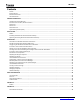
IM 1133-C Contents FIGURES ...................................................................................................................................................................................3 REVISION HISTORY .....................................................................................................................................................................4 REFERENCE DOCUMENTS....................................................................................................
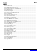
IM 1133-C Figures Figure 1, Maverick II Rooftop Unit .................................................................................................................................................................................... 6 Figure 2, DIII-NET Communication Gateway Installed ..................................................................................................................................................... 7 Figure 3, Mounting bracket installed in unit. ..........................
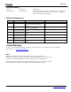
IM 1133-C Revision History IM 1133 August 2011 Initial release IM 1133-RevB November 2013 Revised and expanded on adding a new DIII board to an existing unit, updated all figure numbers. Sections added on iTouch configuration and operation; includes 27 new Figures. Reference Documents Number Company Title Source OM 920 Daikin www.DaikinApplied.
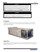
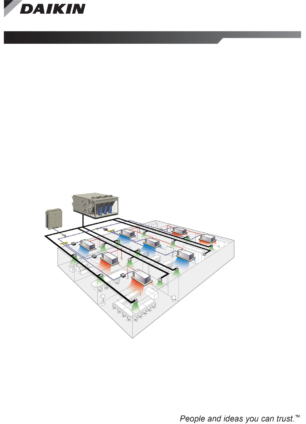
IM 1133-C General Information This manual contains the information you need to install the DIII-NET Communication Gateway on a MicroTech® III Applied Air Handling Unit (AAH) Controller (i.e., RoofPak™ applied rooftop, Maverick™ II commercial rooftop or Self-Contained Unit), incorporate it into the DIII-Net network, and maintain it.
IM 1133-C NOTICE This equipment generates, uses and can radiate radio frequency energy and, if not installed and used in accordance with this instruction manual, may cause interference to radio communications. It has been tested and found to comply with the limits for a Class A digital device, pursuant to part 15 of the FCC rules. These limits are designed to provide reasonable protection against harmful interference when the equipment is operated in a commercial environment.
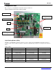
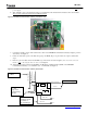
IM 1133-C Component Data Major components of the DIII-NET Communication Gateway are labeled in . Figure 2, DIII-NET Communication Gateway Installed 24VAC DIII Communication Port LED’s H1P through H7P. DS1 Part Number DS2 Modbus Communication Port Light Emitting Diodes (LEDs) The LED’s on the DIII-NET Communication Gateway are used to indicate either the DIII-NET Communication Gateway is working correctly or there is a fault.
IM 1133-C Installation The DIII-NET Communication Gateway will be factory installed. If it is necessary to replace this board, see section Replacing DIII-NET Communication Gateway. If a new board is being installed on an existing unit, see section Installing a New DIII_NET Communication Gateway. Wiring ! CAUTION Electrostatic discharge hazard. Can cause equipment damage. This equipment contains sensitive electronic components that may be damaged by electrostatic discharge from your hands.
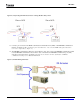
IM 1133-C 5. Install 120/24 VAC transformer in the control cabinet. The DIII-NET Communication Gateway must have its own, power supply. 6. Wire 120VAC power to the transformer using open terminals from the T1 transformer inside the unit control cabinet. The secondary of this transformer must remain ungrounded. Figure 4, DIII-NET Communication Gateway mounted in unit 7. Connect the 24VAC power from the transformer to X6A on the DIII-NET Communication Gateway using the provided wire harness.
IM 1133-C Figure 6, Incorporating DIII-NET board into an existing Modbus Daisy Chain 11. Connect a pair of wires from the MCB to the Modbus Communication Port (X2M) on the DIII-NET Communication Gateway. See Figure 5. (There should be 2 pairs of modbus wires connected to the MCB at this point, unless there were none to begin with, see Figure 6.) 12. The DIII-NET Communications Gateway is treated like any other outdoor unit on the DIII-NET communications trunk.
IM 1133-C 13. Position the binary DIP switches on the DIII-NET Communication Gateway to “0110 1010” as configured in Figure 8. 14. Power up the Daikin Applied Air Handling Unit, MicroTech III Unit Controller and DIII-NET Communication Gateway. 15. Configure MicroTech III and Daikin VRV unit controllers as instructed in the Integration section. For information on the iTouch Manager, refer to user’s manual EM11A017.
IM 1133-C Integration Once the DIII-NET Communication Gateway has been properly installed on the unit and connected to a DIII network, it is then possible to integrate the unit controller with a Daikin Intelligent Touch Controller or iTouch Manager over a DIII network. The integration process is described in the following section.
IM 1133-C DIII-NET Communication Gateway Addressing Before a unit can be viewed and controlled through a DIII network, the DIII-NET Communication Gateway must be assigned a DIII address. Configuring the DIII board is done through the MicroTech III unit controller. The following diagram in Figure 9 details the menu structure of the MicroTech III Applied Air Handling Unit Controller related to the DIII-NET Communication Gateway.
IM 1133-C Configuring the DIII Board and MicroTech III Controller 1. 2. 3. 4. 5. 6. 7. 8. 9. Navigate to the Enter Password screen if you have not already entered a password. If you have entered a password, skip to step 3. Enter Password: 6363. Navigate to Commission Unit\D3 Set Up menu In the D3 Set-Up menu, set “ITouch Version” as desired a. “USw/Spt” – For use with Intelligent Touch Controller software versions 6.XX and iTouch Manager software versions 2.XX.
IM 1133-C Intelligent Touch Controller Configuration The Intelligent Touch Controller also needs to be configured. This section shows how to change the icon for a zone and how to set the dead band to zero. Refer to the Intelligent Touch controller Manual (ED72-423) for more information on navigating the Intelligent Touch Controller menus. The Intelligent Touch controller Manual is available on www.daikinac.com.
IM 1133-C Figure 13, Zone / Group Screen Settings Button 5. Use the triangular Up and Down arrow buttons to change the icon as desired and then press OK. Figure 14, Group Settings Screen Change icon buttons. DIII-NET COMMUNICATION GATEWAY 16 www.DaikinApplied.
IM 1133-C Creating a New Zone and Setting the Intelligent Touch Controller Dead Band 1. From the main screen the zone “All” should be highlighted, as in Figure 15. From this screen press the Settings button in the lower right corner, indicated with the red arrow. Figure 15, All Zones Display on Intelligent Touch Controller Settings Button 2. In the Settings Menu press the down arrow, select “System” and then press Execute. Figure 16, System Settings Screen Down Button 3.
IM 1133-C Highlight the unit DIII-NET Communication Gateway address from the “Group” box. Press the double arrow button to add the unit to that zone. Figure 18, System Zone Group Screen Group box Zone List box DIII-NET address New zone group Double Arrow Button Add Button 5. Press the “OK” button twice to get back to the main screen. The main screen should look similar to Figure 19 below.
IM 1133-C 6. From the Configure screen press the “Setpoint Range” button. Then press OK. Figure 20, Configure Screen for Setting Setpoint Range Setpoint Range Button 7. From the “Setpoint Range” screen, set “Min Cool/Heat SP Differential” to “0*”. Figure 21, Setpoint Range Configuration Screen Set to Zero* DIII-NET COMMUNICATION GATEWAY 19 www.DaikinApplied.
IM 1133-C Intelligent Touch Controller Operation The following section describes basic operation related to the MicroTech® III Air Handling unit through the Intelligent Touch Controller interface. Refer to ED72-423 for more information about the operation of the Intelligent Touch Controller, available on www.daikinac.com. MicroTech III Unit Operation 1. Figure 22 shows the MicroTech III Air Handling unit running in Occupied mode. Figure 22, MicroTech III Air Handling Unit in Occupied Mode 2.
IM 1133-C Figure 24, MicroTech III Air Handler in Unoccupied Operation Adjusting Discharge Air Setpoint Note: This only applies if ‘Std’ or ‘USw/Spt’ is selected for iTouch Version. Refer to DIII-Net Communication Gateway Addressing section for more information. Note: Discharge air temperature setpoint cannot be adjusted with ‘USw/oSpt’ selected. 1. Highlight the MicroTech III Air Handling unit and select Configure. Figure 25, With MicroTech III Air Handling Unit Selected Configure Button 2.
IM 1133-C Figure 26, Configure Screen for MicroTech III Air Handling Unit Std Version Modify Button 3. For ‘USw/Spt’ versions select Modify for either setpoint. Figure 27, Configure Screen for MicroTech III Air Handling Unit US Version. Note: For both versions, modifying the setpoint will adjust the discharge air setpoint for whatever mode the unit is currently in.
IM 1133-C Figure 28, MicroTech III Air Handling Unit Selected. Configure Button 2. On the Configuration Screen, press the Advanced Settings button. Advanced Settings Button 3. On the Advanced Settings screen, select the desired Fan Speed setting and press OK. Figure 29, Advanced Settings Configuration Screen Fan Speed Settings DIII-NET COMMUNICATION GATEWAY 23 www.DaikinApplied.
IM 1133-C iTouch Manager Configuration The iTouch Manager (iTM) also needs to be configured. This section shows how to add units to the iTM, change the icon for a zone and how to set the dead band to zero. Refer to manuals EM11A017 and EM11A022 for more details regarding the operation and commissioning of the iTouch Manager. The iTM manuals are available on www.daikinac.com.
IM 1133-C Figure 32, Service Login Screen Enter Password OK Figure 33, Service Login Menu List – Auto Register Service Settings Tab AutoRegist Button 5. Go to the Service Settings Tab and Select “A/C AutoRegist” See Figure 33. 6. Select the units you want to register on the A/C Auto Register Screen and press “OK.” See Figure 34. If no units are available to select, the unit(s) may have to be added manually. See the next section, “Manually Add a Unit to the iTouch Manager,” for more information.
IM 1133-C Figure 35, Confirm Auto Register Changes Manually Add a Unit to the iTouch Manager Most Daikin AHU’s are not recognized by the iTM’s Auto Register feature. Because of this, it is often necessary to register a unit to the iTouch Manager manually. To manually add a unit to the iTM: 1. Select the “Menu List” button from the bottom of the home screen. See Figure 30. 2. From the Menu List Screen, tap the 4 corners of the screen to access the service login. See Figure 31. 3.
IM 1133-C Figure 37, Add Management Point to iTouch Manager Add Figure 38, Management Point Type Indoor Unit 8. Under the Management Point Attributes Menu, set the DIII address using the drop-down menus. See Figures 39 and 40. This address must match the DIII board’s address as previously set by the MicroTech III Unit Controller. See section “DIII-NET Communication Gateway Addressing” steps 5-7. 9. Set the name of the unit by clicking “Modify” next to “Name.” See Figure 39.
IM 1133-C Figure 41, Setting Unit Name 10. After the unit’s address and name have been set, press OK. The unit should now appear on the Management Point Data Register Menu. See Figure 42. 11. Select OK to register the unit. See Figure 42. Figure 42, New Management Point on iTouch Manager 12. When prompted to confirm the changes, select OK. See Figure 43. The iTM will immediately shutdown after confirmation. After it has automatically rebooted, the unit should be registered.
IM 1133-C Changing Icon and Description on iTouch Manager 1. Select Menu List from the home screen. See Figure 30. 2. From the Menu List Screen, tap the 4 corners of the screen as shown in Figure 31 to access the service login. 3. Enter the password “daikin” and press OK. See Figure 32. 4. A red frame will appear around the edges of the screen when the service login is active. See Figure 36. 5. Go to the Service Settings Tab and Select “Mgmt.Pnt DataRegist” See Figure 36. 6.
IM 1133-C Figure 46, Entering Detailed Information 9. To change the unit’s icon, select Modify next to “Icon” See Figure 45. 10. A list of icons will appear as shown in Figure 47. Select the desired icon and press OK. 11. Select OK to exit menu. Figure 47, Icon Selection 12. When prompted to confirm the changes, select OK. The iTM will save the changes and shutdown. When the iTM has rebooted the changes will have been applied. See Figure 43. DIII-NET COMMUNICATION GATEWAY 30 www.DaikinApplied.
IM 1133-C iTouch Manager Operation This section describes the operation of the iTouch Manager to monitor and control Daikin Applied Air Handler Units. Refer to EM11A017 for more information about the operation of the iTouch Manager, available on www.daikinac.com. If the Intelligent Touch Controller is being used, see section “Intelligent Touch Controller Operation” Turning a Unit On and Off The iTouch Manager allows units to be easily turned on and off directly from the device list screen. 1.
IM 1133-C Adjusting Setpoints Note: This only applies if ‘Std’ or ‘USw/Spt’ is selected for iTouch Version. Refer to DIII-Net Communication Gateway Addressing section for more information. The discharge air temperature setpoint cannot be adjusted with ‘USw/oSpt’ selected. The iTouch Manager adjusts the active setpoint of an AHU. If the unit is in cooling mode, the iTM will adjust the cooling setpoint, if the unit is in heating mode the heating setpoint will be adjusted.
IM 1133-C Figure 51, Adjusting Fan Speed from the iTouch Manager Change Fan Speed Selected Unit Advanced Settings The Detailed Setup screen allows multiple changes to be made to a unit at once. As well as containing standard controls such as On/Off and Setpoints, this screen also has several advanced settings. Main Tab – Unit Settings 1. Access the Indoor Devices list. See section “Turning a Unit On and Off” steps 1 and 2. 2.
IM 1133-C Figure 53, Detailed Settings Screen On/Off Main Tab A/C Tab R/C Prohibition Tab Adjust Setpoint Min Cool/Heat SP Differential Setpoint Tracking OK 5. Press OK to save changes. 6. When prompted, confirm unit setup. Changes will be sent to the unit controller. A/C Tab – Setpoint Restrictions 1. Select the A/C tab from the Detailed Settings screen. See Figure 53. 2. Select the checkbox next to “Setpoint Restriction.” 3.
IM 1133-C 6. Note: When prompted, confirm unit setup. Changes will be sent to the unit controller. The MicroTech III’s internal setpoint restrictions will always be enforced, regardless of iTouch Manager’s settings. Enabling setpoint restrictions in the iTouch Manager imposes additional restrictions on the range of setpoints that can be sent to the unit controller for more precise management over the space temperatures and energy savings.
IM 1133-C Service Information Test Procedures If you can control the unit from its keypad, but you are not able to communicate with unit via the DIII network, follows these steps: Check the network wiring. Check the network parameters and verify that they are correct, and that there are no duplicate devices on the network. (Addresses must be unique.) See section “DIII Communication Gateway Addressing” Verify that the MicroTech III controller is setup correctly.
IM 1133-C Appendix A Alarms When an alarm is triggered, it will appear on both the MicroTech III unit and the Intelligent Touch Controller. Below is a list of alarms and their corresponding level, number, code and description.
IM 1133-C Appendix B Configurable Parameters Table 4 defines the different parameters that are available in the D3 Set Up menu. The default values and acceptable ranges of values are also included.
IM 1133-C Daikin Applied Training and Development Now that you have made an investment in modern, efficient Daikin equipment, its care should be a high priority. For training information on all Daikin HVAC products, please visit us at www.DaikinApplied.com and click on Training, or call 540-248-9646 and ask for the Training Department. Warranty All Daikin equipment is sold pursuant to its standard terms and conditions of sale, including Limited Product Warranty.