
Service manual

Printed Circuit Board Connector Wiring Diagram SiBE07-724_B
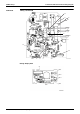
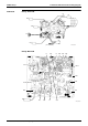
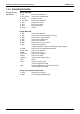
26 Printed Circuit Board Connector Wiring Diagram
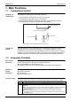
1.2.3 RK(X)S25/35G2V1B9
Connectors and
Other Parts
PCB (1): Filter PCB
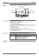
PCB (2): Main PCB
PCB (3): Forced Operation Button PCB
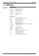
1) S11 Connector for main PCB
2) AC1, AC2, S Connector for terminal board
3) E1, E2 Terminal for earth
4) HL2, HN2 Connector for main PCB
5) HR1 Connector for reactor
6) FU1 Fuse (3.15 A, 250 V)
7) FU3 Fuse (20 A, 250 V)
8) V2, V3 Varistor
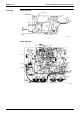
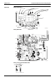
1) S10 Connector for filter PCB
2) S20 Connector for electronic expansion valve coil
3) S40 Connector for overload protector
4) S50 Connector for magnetic relay
5) S70 Connector for fan motor
6) S80 Connector for four way valve coil
7) S90 Connector for thermistors
(outdoor temperature, outdoor heat exchanger, discharge pipe)
8) S100 Connector for forced operation button PCB
9) HL3, HN3 Connector for filter PCB
10)HR2 Connector for reactor
11)U, V, W Connector for compressor
12)FU2 Fuse (3.15 A, 250 V)
13)LED A LED for service monitor (green)
14)V1 Varistor
15)J4 Jumper for facility setting
∗
Refer to page 204 for detail.
16)J5 Jumper for improvement of defrost performance
∗
Refer to page 205 for detail.
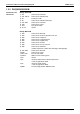
1) S110 Connector for main PCB
2) SW1 Forced operation ON/OFF button