
Service manual

Check SiBE07-724_B
114 Service Diagnosis
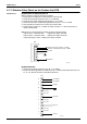
Step 3
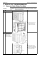
Activate inverter test operation from the outdoor unit.
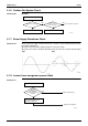
1) Press the forced cooling operation ON/OFF button for 5 seconds.
(Refer to page 199 for the position.)
→
Inverter test operation starts.
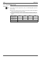
Diagnose method (Diagnose according to 6 LEDs lighting status.)
(1) When all the LEDs are lit uniformly, the compressor is defective.
→
Replace the compressor.
(2) When the LEDs are not lit uniformly, check the power module.
→
Refer to Check No.13.
(3) If NG in Check No.13, replace the power module (control PCB).
If OK in Check No.13, check if there is any solder cracking on the filter PCB.
(4) If any solder cracking is found, replace the filter PCB or repair the soldered section.
If the filter PCB is OK, replace the control PCB.
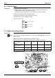
Caution
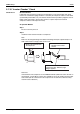
(1) When the output frequency is low, the LEDs blink slowly. As the output frequency increases,
the LEDs blink quicker. (The LEDs look like they are lit.)
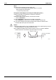
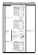
(2) On completion of diagnose by the inverter checker, be sure to re-crimp the FASTON
terminals. Otherwise, the terminals may be burned due to loosening.
(R5161)
Direction of crimp
FASTON terminal
This size is shortened
by “crimp”.