SiBE07-724_B Service Manual Inverter Pair Duct Connected Type CA-Series EA-Series [Applied Models] ● Inverter Pair : Cooling Only ● Inverter Pair : Heat Pump
SiBE07-724_B Inverter Pair Duct Connected Type CA-Series EA-Series zCooling Only Indoor Unit FDKS25CAVMB FDKS35CAVMB FDKS25EAVMB FDKS35EAVMB Outdoor Unit RKS25E2V1B RKS35E2V1B RKS25G2V1B RKS35G2V1B RKS25G2V1B9 RKS35G2V1B9 zHeat Pump Indoor Unit FDXS25CAVMB FDXS35CAVMB FDXS25EAVMB FDXS35EAVMB Outdoor Unit RXS25E2V1B RXS35E2V1B i RXS25G2V1B RXS35G2V1B RXS25G2V1B9 RXS35G2V1B9 Table of Contents
SiBE07-724_B 1. Introduction .............................................................................................v 1.1 Safety Cautions ........................................................................................v 1.2 Used Icons .............................................................................................. ix Part 1 List of Functions ................................................................ 1 1. Functions...........................................................
SiBE07-724_B Part 5 Operation Manual ............................................................. 55 1. System Configuration............................................................................56 2. Operation Manual..................................................................................57 2.1 2.2 2.3 2.4 2.5 2.6 Remote Controller ..................................................................................57 AUTO · DRY · COOL · HEAT · FAN Operation ..................................
SiBE07-724_B 1.4 1.5 1.6 1.7 Removal of Reactor / Partition Plate ....................................................133 Removal of Sound Blanket...................................................................135 Removal of Four Way Valve.................................................................137 Removal of Compressor.......................................................................140 2. Outdoor Unit - RK(X)S25/35G2V1B....................................................142 2.1 2.2 2.
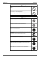
Introduction SiBE07-724_B 1. Introduction 1.1 Safety Cautions Cautions and Warnings Be sure to read the following safety cautions before conducting repair work. The caution items are classified into “ Warning” and “ Caution”. The “ Warning” items are especially important since they can lead to death or serious injury if they are not followed closely. The “ Caution” items can also lead to serious accidents under some conditions if they are not followed.
SiBE07-724_B Introduction Warning Be sure to wear a safety helmet, gloves, and a safety belt when working at a high place (more than 2 m). Insufficient safety measures may cause a fall accident. In case of R-410A refrigerant models, be sure to use pipes, flare nuts and tools for the exclusive use of the R-410A refrigerant. The use of materials for R-22 refrigerant models may cause a serious accident such as a damage of refrigerant cycle as well as an equipment failure.
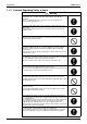
Introduction SiBE07-724_B 1.1.2 Cautions Regarding Safety of Users Warning Be sure to use parts listed in the service parts list of the applicable model and appropriate tools to conduct repair work. Never attempt to modify the equipment. The use of inappropriate parts or tools may cause an electrical shock, excessive heat generation or fire. If the power cable and lead wires have scratches or deteriorated, be sure to replace them.
SiBE07-724_B Introduction Warning Check to make sure that the power cable plug is not dirty or loose, then insert the plug into a power outlet securely. If the plug has dust or loose connection, it may cause an electrical shock or fire. Be sure to install the product correctly by using the provided standard For unitary type installation frame. only Incorrect use of the installation frame and improper installation may cause the equipment to fall, resulting in injury.
Introduction SiBE07-724_B Caution Be sure to measure the insulation resistance after the repair, and make sure that the resistance is 1 MΩ or higher. Faulty insulation may cause an electrical shock. Be sure to check the drainage of the indoor unit after the repair. Faulty drainage may cause the water to enter the room and wet the furniture and floor. Do not tilt the unit when removing it. The water inside the unit may spill and wet the furniture and floor.
SiBE07-724_B Part 1 List of Functions 1. Functions.................................................................................................2 1.1 Cooling Only.............................................................................................2 1.2 Heat Pump ...............................................................................................
Functions SiBE07-724_B 1.
Compressor Comfortable Airflow Comfort Control { Operation Limit for Cooling (°CDB) –10 ~46 ★ Operation Limit for Heating (°CWB) — — PAM Control { { Lifestyle Convenience Air-Purifying Filter — — Photocatalytic Deodorizing Filter — — Air-Purifying Filter with Photocatalytic Deodorizing Function — — Category Health & Clean Functions Standby Electricity Saving — { Oval Scroll Compressor — — Titanium Apatite Photocatalytic Air-Purifying Filter — — Swing Compressor { { Air F
Category Basic Function Compressor Comfortable Airflow Comfort Control Operation Lifestyle Convenience Functions Inverter (with Inverter Power Control) Operation Limit for Cooling (°CDB) Operation Limit for Heating (°CWB) — PAM Control { Health & Clean Functions Air-Purifying Filter — Photocatalytic Deodorizing Filter — Air-Purifying Filter with Photocatalytic Deodorizing Function — Standby Electricity Saving { Oval Scroll Compressor — Titanium Apatite Photocatalytic Air-Purifying Fi
SiBE07-724_B Compressor Comfortable Airflow Comfort Control Operation Lifestyle Convenience { { Operation Limit for Cooling (°CDB) –10 ~46 –10 ~46 Operation Limit for Heating (°CWB) –15 ~20 –15 ~20 Inverter (with Inverter Power Control) FDXS25/35CAVMB RXS25/35G2V1B Basic Function Functions FDXS25/35CAVMB RXS25/35E2V1B Category FDXS25/35CAVMB RXS25/35G2V1B Heat Pump FDXS25/35CAVMB RXS25/35E2V1B 1.
Compressor Comfortable Airflow Comfort Control Operation Lifestyle Convenience { { Operation Limit for Cooling (°CDB) –10 ~46 –10 ~46 Operation Limit for Heating (°CWB) –15 ~20 –15 ~20 Inverter (with Inverter Power Control) FDXS25/35EAVMB RXS25/35G2V1B Basic Function Functions FDXS25/35EAVMB RXS25/35E2V1B Category FDXS25/35EAVMB RXS25/35G2V1B SiBE07-724_B FDXS25/35EAVMB RXS25/35E2V1B Functions Air-Purifying Filter — — Photocatalytic Deodorizing Filter — — Air-Purifying Filter wi
Basic Function Compressor Comfortable Airflow Comfort Control Operation Lifestyle Convenience Functions Inverter (with Inverter Power Control) { Operation Limit for Cooling (°CDB) –10 ~46 Operation Limit for Heating (°CWB) –15 ~20 Category Health & Clean Functions FDXS25/35EAVMB RXS25/35G2V1B9 Category Functions FDXS25/35EAVMB RXS25/35G2V1B9 SiBE07-724_B Air-Purifying Filter — Photocatalytic Deodorizing Filter — Air-Purifying Filter with Photocatalytic Deodorizing Function — — PAM
SiBE07-724_B Part 2 Specifications 1. Specifications ..........................................................................................9 1.1 Cooling Only.............................................................................................9 1.2 Heat Pump .............................................................................................
SiBE07-724_B Specifications 1. Specifications 1.1 Cooling Only 50 Hz, 230 V Models Indoor Units Outdoor Units Moisture Removal Running Current (Rated) Power Consumption Rated (Min. ~ Max.) Power Factor COP (Rated) Liquid Piping Connections Gas Drain Heat Insulation Max. Interunit Piping Length Max. Interunit Height Difference Chargeless Amount of Additional Charge of Refrigerant Indoor Units External Static Pressure 690 1,090 % W/W mm mm mm 75.4 3.48 φ 6.4 φ 9.5 VP20 (O.D. φ 26 / I.D.
Specifications SiBE07-724_B 50 Hz, 230 V Models Indoor Units Outdoor Units Moisture Removal Running Current (Rated) Power Consumption Rated (Min. ~ Max.) Power Factor COP (Rated) Liquid Piping Connections Gas Drain Heat Insulation Max. Interunit Piping Length Max. Interunit Height Difference Chargeless Amount of Additional Charge of Refrigerant Indoor Units External Static Pressure 690 1,090 % W/W mm mm mm 75.4 3.48 φ 6.4 φ 9.5 VP20 (O.D. φ 26 / I.D. φ 20) Both Liquid and Gas Pipes 20 15 10 95.0 3.
SiBE07-724_B Specifications 50 Hz, 230 V Models Indoor Units Outdoor Units Moisture Removal Running Current (Rated) Power Consumption Rated (Min. ~ Max.) Power Factor COP (Rated) Liquid Piping Connections Gas Drain Heat Insulation Max. Interunit Piping Length Max. Interunit Height Difference Chargeless Amount of Additional Charge of Refrigerant Indoor Units External Static Pressure 690 1,090 % W/W mm mm mm 75.4 3.48 φ 6.4 φ 9.5 VP20 (O.D. φ 26 / I.D. φ 20) Both Liquid and Gas Pipes 20 15 10 95.0 3.
Specifications 1.2 SiBE07-724_B Heat Pump 50 Hz, 230 V Indoor Units Models FDXS25CAVMB RXS25E2V1B Outdoor Units Capacity Rated (Min. ~ Max.) Moisture Removal Running Current (Rated) Power Consumption Rated (Min. ~ Max.) Power Factor COP (Rated) Liquid Piping Connections Gas Drain Heat Insulation Max. Interunit Piping Length Max. Interunit Height Difference Chargeless Amount of Additional Charge of Refrigerant Indoor Units External Static Pressure Airflow Rate Note: Cooling 2.4 (1.3 ~ 3.
SiBE07-724_B Specifications 50 Hz, 230 V Indoor Units Models FDXS25CAVMB RXS25G2V1B Outdoor Units Capacity Rated (Min. ~ Max.) Moisture Removal Running Current (Rated) Power Consumption Rated (Min. ~ Max.) Power Factor COP (Rated) Liquid Piping Connections Gas Drain Heat Insulation Max. Interunit Piping Length Max. Interunit Height Difference Chargeless Amount of Additional Charge of Refrigerant Indoor Units External Static Pressure Airflow Rate Note: Cooling 2.4 (1.3 ~ 3.
Specifications SiBE07-724_B 50 Hz, 230 V Indoor Units Models FDXS25EAVMB RXS25E2V1B Outdoor Units Capacity Rated (Min. ~ Max.) Moisture Removal Running Current (Rated) Power Consumption Rated (Min. ~ Max.) Power Factor COP (Rated) Liquid Piping Connections Gas Drain Heat Insulation Max. Interunit Piping Length Max. Interunit Height Difference Chargeless Amount of Additional Charge of Refrigerant Indoor Units External Static Pressure Airflow Rate Note: Cooling 2.4 (1.3 ~ 3.
SiBE07-724_B Specifications 50 Hz, 230 V Indoor Units Models FDXS25EAVMB RXS25G2V1B Outdoor Units Capacity Rated (Min. ~ Max.) Moisture Removal Running Current (Rated) Power Consumption Rated (Min. ~ Max.) Power Factor COP (Rated) Liquid Piping Connections Gas Drain Heat Insulation Max. Interunit Piping Length Max. Interunit Height Difference Chargeless Amount of Additional Charge of Refrigerant Indoor Units External Static Pressure Airflow Rate Note: Cooling 2.4 (1.3 ~ 3.
Specifications SiBE07-724_B 50 Hz, 230 V Indoor Units Models FDXS25EAVMB RXS25G2V1B9 Outdoor Units Capacity Rated (Min. ~ Max.) Moisture Removal Running Current (Rated) Power Consumption Rated (Min. ~ Max.) Power Factor COP (Rated) Liquid Piping Connections Gas Drain Heat Insulation Max. Interunit Piping Length Max. Interunit Height Difference Chargeless Amount of Additional Charge of Refrigerant Indoor Units External Static Pressure Airflow Rate Note: Cooling 2.4 (1.3 ~ 3.
SiBE07-724_B Part 3 Printed Circuit Board Connector Wiring Diagram 1. Printed Circuit Board Connector Wiring Diagram..................................20 1.1 Indoor Unit..............................................................................................20 1.2 Outdoor Unit ...........................................................................................
Printed Circuit Board Connector Wiring Diagram SiBE07-724_B 1. Printed Circuit Board Connector Wiring Diagram 1.
SiBE07-724_B PCB Detail Printed Circuit Board Connector Wiring Diagram PCB (1): Control PCB FU1 S1 H2 H1 H3 V1 GND S7 S21 S26 LED A JA JB JC S32 2P131149-1 PCB (2): Display PCB S1 LED3 LED2 RTH1 SW1 Printed Circuit Board Connector Wiring Diagram LED1 21
Printed Circuit Board Connector Wiring Diagram 1.2 SiBE07-724_B Outdoor Unit 1.2.
SiBE07-724_B PCB Detail Printed Circuit Board Connector Wiring Diagram PCB (1): Filter PCB HC2 HR1 E HL1 HN1 S HN2 S11 HC1 HL2 V3 V2 FU3 3P143310-1 PCB (2): Main PCB S10 S40 LED A S90 S30 S70 SW1 J5 HC3 J8 HN3 FU2 HR2 HC4 S20 Printed Circuit Board Connector Wiring Diagram S80 V1 FU1 HL3 2P143284-6 23
Printed Circuit Board Connector Wiring Diagram SiBE07-724_B 1.2.
SiBE07-724_B PCB Detail Printed Circuit Board Connector Wiring Diagram PCB (1): Filter PCB E1 E2 HR1 HL1 HN1 S V3 V2 HN2 FU3 S11 HL2 S50 (on main PCB) 3P203203-1 PCB (2): Main PCB J5 S10 J8 S90 S40 S50 S30 LED A SW1 S70 FU1 HN3 FU2 HR2 HL3 S80 V1 S20 2P203198-1 Printed Circuit Board Connector Wiring Diagram 25
Printed Circuit Board Connector Wiring Diagram SiBE07-724_B 1.2.3 RK(X)S25/35G2V1B9 Connectors and Other Parts PCB (1): Filter PCB 1) 2) 3) 4) 5) 6) 7) 8) S11 AC1, AC2, S E1, E2 HL2, HN2 HR1 FU1 FU3 V2, V3 Connector for main PCB Connector for terminal board Terminal for earth Connector for main PCB Connector for reactor Fuse (3.
SiBE07-724_B PCB Detail Printed Circuit Board Connector Wiring Diagram PCB (1): Filter PCB HR1 E1, E2 HN2 V2 AC2 AC1 V3 S11 FU3 S FU1 HL2 S50 (on main PCB) 3P254234-1 PCB (2): Main PCB U VW S10 J5 J4 S90 LED A S70 S40 HR2 S20 S80 HL3 V1 HN3 FU2 S100 S50 2P254206-1 PCB (3): Forced Operation Button PCB SW1 S110 3P255755-1 Printed Circuit Board Connector Wiring Diagram 27
SiBE07-724_B Part 4 Function and Control 1. Main Functions......................................................................................29 1.1 1.2 1.3 1.4 1.5 1.6 1.7 1.8 1.9 1.10 Temperature Control ..............................................................................29 Frequency Principle................................................................................29 Fan Speed Control for Indoor Units........................................................31 Program Dry Operation ....
SiBE07-724_B Main Functions 1. Main Functions 1.1 Temperature Control Definitions of Temperatures The definitions of temperatures are classified as following.
Main Functions Drawing of Inverter SiBE07-724_B The following drawing shows a schematic view of the inverter principle: Refrigerant circulation rate (high) AC power Amount of heat exchanged air (small) DC power high speed Amount of heat exchanged air (large) high f low f low speed 50 Hz freq= constant 60 Hz freq=variable Amount of heat exchanged air (large) Amount of heat exchanged air (small) capacity= variable Refrigerant circulation rate (low) Inverter Features (R2812) The inverter provid
SiBE07-724_B 1.3 Main Functions Fan Speed Control for Indoor Units Outline Phase control and fan speed control contains 9 steps: LLL, LL, SL, L, ML, M, MH, H, and HH. The airflow rate can be automatically controlled depending on the difference between the room thermistor temperature and the target temperature. This is done through phase control and Hall IC control. For more information about Hall IC, refer to the troubleshooting for fan motor on page 76.
Main Functions 1.4 SiBE07-724_B Program Dry Operation Outline Program dry operation removes humidity while preventing the room temperature from lowering. Since the microcomputer controls both the temperature and airflow rate, the temperature adjustment and fan adjustment buttons are inoperable in this mode. Detail The microcomputer automatically sets the temperature and airflow rate.
SiBE07-724_B 1.5 Main Functions Automatic Operation Outline Detail Automatic Cooling / Heating Function When the AUTO mode is selected with the remote controller, the microcomputer automatically determines the operation mode as cooling or heating according to the room temperature and the set temperature at start-up, and automatically operates in that mode. The unit automatically switches the operation mode to maintain the room temperature at the set temperature.
Main Functions 1.6 SiBE07-724_B Thermostat Control Thermostat control is based on the difference between the room thermistor temperature and the target temperature. Thermostat OFF Condition The temperature difference is in the zone A. Thermostat ON Condition The temperature difference returns to the zone C after being in the zone A. The system resumes from defrost control in any zones except A. The operation turns on in any zones except A.
SiBE07-724_B 1.7 Main Functions NIGHT SET Mode Outline When the OFF timer is set, the NIGHT SET Mode is automatically activated. The NIGHT SET Mode keeps the airflow rate setting. Detail The NIGHT SET Mode continues operation at the target temperature for the first one hour, then automatically raises the target temperature slightly in the case of cooling, or lowers it slightly in the case of heating.
Main Functions 1.8 SiBE07-724_B HOME LEAVE Operation Outline HOME LEAVE operation is a function that allows you to record your favorite set temperature and airflow rate. You can start your favorite operation mode simply by pressing the [HOME LEAVE] button on the remote controller. Detail 1. Start of Function The function starts when the [HOME LEAVE] button is pressed in cooling mode, heating mode (including POWERFUL operation), or while the operation is stopped.
SiBE07-724_B 1.9 Main Functions Inverter POWERFUL Operation Outline In order to exploit the cooling and heating capacity to full extent, operate the air conditioner by increasing the indoor fan rotating speed and the compressor frequency. Detail When POWERFUL button is pressed, the fan speed and target temperature are converted to the following states for 20 minutes. Operation mode Fan speed Target temperature COOL DRY H tap + 50 rpm Dry rotating speed + 50 rpm 18°C Lowered by 2.
Main Functions SiBE07-724_B 1.10 Other Functions 1.10.1 Hot-Start Function In order to prevent the cold air blast that normally comes when heating operation is started, the temperature of the indoor heat exchanger is detected, and either the airflow is stopped or is made very weak thereby carrying out comfortable heating of the room. *The cold air blast is also prevented using a similar control when the defrosting operation is started or when the thermostat is turned ON. 1.10.
SiBE07-724_B Function of Thermistor 2. Function of Thermistor Cooling Only Electronic expansion valve A C Compressor B (R11611) Heat Pump A Electronic expansion valve C Four way valve B Compressor (R11591) A Outdoor Heat Exchanger Thermistor 1. The outdoor heat exchanger thermistor is used for controlling target discharge pipe temperature.
Control Specification SiBE07-724_B 3. Control Specification 3.1 Mode Hierarchy Outline There are two modes; the one is the normal operation mode and the other is the forced operation mode for installation and providing service. Detail For Cooling Only Model There are following modes; stop and cooling (including drying).
SiBE07-724_B 3.2 Control Specification Frequency Control Outline Frequency is determined according to the difference between the room thermistor temperature and the target temperature. The function is explained as follows. 1. How to determine frequency 2. Frequency command from the indoor unit (Difference between the room thermistor temperature and the target temperature) 3. Frequency initial setting 4.
Control Specification SiBE07-724_B 2. Determine upper limit frequency The minimum value is set as an upper limit frequency among the frequency upper limits of the following functions: Compressor protection, input current, discharge pipe temperature, heating peak-cut, freezeup protection, defrost. 3.
SiBE07-724_B 3.3 Control Specification Controls at Mode Changing / Start-up 3.3.1 Preheating Operation Outline The inverter operation in open phase starts with the conditions of the preheating command from the indoor unit, the outdoor temperature, and the discharge pipe temperature. Detail RK(X)S25/35E2V1B, RK(X)S25/35G2V1B ON Condition When the discharge pipe temperature is below 10ºC, the inverter operation in open phase starts.
Control Specification SiBE07-724_B 3.3.2 Four Way Valve Switching Outline In heating operation, current is conducted, and in cooling and defrosting, current is not conducted. In order to eliminate the switching sound when the heating is stopped, as the four way valve coil switches from ON to OFF, the OFF delay switch of the four way valve is carried out after the operation stopped.
SiBE07-724_B 3.4 Control Specification Discharge Pipe Temperature Control Outline The discharge pipe temperature is used as the internal temperature of the compressor. If the discharge pipe temperature rises above a certain level, the upper limit of frequency is set to keep this temperature from going up further.
Control Specification 3.5 Outline SiBE07-724_B Input Current Control The microcomputer calculates the input current during the compressor is running, and sets the frequency upper limit from the input current. In case of heat pump model, this control which is the upper limit control of the frequency takes priority to the lower limit of control of four way valve operation compensation.
SiBE07-724_B 3.6 Control Specification Freeze-up Protection Control Outline During cooling operation, the signal sent from the indoor unit controls the operating frequency limitation and prevents freezing of the indoor heat exchanger. (The signal from the indoor unit is divided into zones.) Detail The operating frequency limitation is judged with the indoor heat exchanger temperature.
Control Specification 3.8 SiBE07-724_B Outdoor Fan Control 1. Fan OFF delay when stopped The outdoor fan is turned OFF 60 seconds after the compressor stops. 2. Fan ON control to cool down the electrical box The outdoor fan is turned ON when the electrical box temperature is high while the compressor is OFF. 3. Fan OFF control while defrosting The outdoor fan is turned OFF while defrosting. 4. Fan ON/OFF control when operation starts / stops The outdoor fan is turned ON when the operation starts.
SiBE07-724_B Control Specification 3.10 Defrost Control Outline Defrosting is carried out by the cooling cycle (reverse cycle). The defrosting time or outdoor heat exchanger temperature must be more than a certain value to finish. Detail Conditions for Starting Defrost The starting conditions is determined with the outdoor temperature and the outdoor heat exchanger temperature. The system is in heating operation. The compressor operates for 6 minutes.
Control Specification SiBE07-724_B 3.11 Electronic Expansion Valve Control Detail The followings are the examples of control which function in each mode by the electronic expansion valve control. Control for abnormally high discharge pipe temperature The following items are included in the electronic expansion valve control. Electronic expansion valve is fully closed 1. Electronic expansion valve is fully closed when turning on the power. 2. Pressure equalizing control Open Control 1.
SiBE07-724_B Control Specification 3.11.1 Fully Closing with Power ON The electronic expansion valve is initialized when turning on the power. The opening position is set and the pressure equalization is developed. 3.11.2 Pressure Equalization Control When the compressor is stopped, the pressure equalization control is activated. The electronic expansion valve opens, and develops the pressure equalization. 3.11.
Control Specification Detail SiBE07-724_B When the starting control (cooling : A seconds, heating : B seconds) finishes, the detection timer for disconnection of the discharge pipe thermistor (C seconds) starts. When the timer is over, the following adjustment is made. 1. When the operation mode is cooling When the following condition is fulfilled, the discharge pipe thermistor disconnection is ascertained. Discharge pipe temperature + 6°C < outdoor heat exchanger temperature 2.
SiBE07-724_B Control Specification 3.12 Malfunctions 3.12.1 Sensor Malfunction Detection Sensor malfunction may occur in the thermistor. Relating to Thermistor Malfunction 1. Outdoor heat exchanger thermistor 2. Discharge pipe thermistor 3. Radiation fin thermistor 4. Outdoor temperature thermistor 3.12.2 Detection of Overcurrent and Overload Outline An excessive output current is detected and, the OL temperature is observed to protect the compressor.
Control Specification SiBE07-724_B 3.13 Standby Electricity Saving RK(X)S25/35G2V1B, RK(X)S25/35G2V1B9 Models Only This function turns power supply OFF to the outdoor unit and sets the indoor unit into energysaving mode, thus reducing the power consumption of the air conditioner. Field setting is required for turning ON the function. Refer to “Standby Electricity Saving” on page 203 for detail.
SiBE07-724_B Part 5 Operation Manual 1. System Configuration............................................................................56 2. Operation Manual..................................................................................57 2.1 2.2 2.3 2.4 2.5 2.6 Operation Manual Remote Controller ..................................................................................57 AUTO · DRY · COOL · HEAT · FAN Operation ......................................58 POWERFUL Operation .....................
System Configuration SiBE07-724_B 1. System Configuration After the installation and test operation of the room air conditioner have been completed, it should be operated and handled as described below. Every user would like to know the correct method of operation of the room air conditioner, to check if it is capable of cooling (or heating) well, and to know a clever method of using it.
SiBE07-724_B Operation Manual 2. Operation Manual 2.1 Remote Controller Remote Controller 1 2 5 3 6 4 9 7 8 10 13 15 14 12 11 < ARC433B69, B76 > 1. Signal transmitter: • It sends signals to the indoor unit. 2. Display: • It displays the current settings. (In this illustration, each section is shown with all its displays ON for the purpose of explanation.) 7. MODE selector button: • It selects the operation mode. (AUTO/DRY/COOL/HEAT/FAN) (page 10.) 4.
Operation Manual 2.2 SiBE07-724_B AUTO · DRY · COOL · HEAT · FAN Operation AUTO · DRY · COOL · HEAT · FAN Operation The air conditioner operates with the operation mode of your choice. From the next time on, the air conditioner will operate with the same operation mode. To start operation 1. Press “MODE selector button” and select a operation mode. • Each pressing of the button advances the mode setting in sequence. 4 : AUTO : DRY 2, 3 1 : COOL : HEAT : FAN 5 2.
SiBE07-724_B Operation Manual To change the air flow rate setting 5. Press “FAN setting button”. DRY mode AUTO or COOL or HEAT or FAN mode Five levels of air flow rate setting from “ plus “ ”“ ” to “ ” ” are available. The air flow rate setting is not variable. • Indoor unit quiet operation When the air flow is set to “ ”, the noise from the indoor unit will become quieter. Use this when making the noise quieter. The unit might lose power when the fan strength is set to a weak level.
Operation Manual 2.3 SiBE07-724_B POWERFUL Operation POWERFUL Operation POWERFUL operation quickly maximizes the cooling (heating) effect in any operation mode. You can get the maximum capacity . To start POWERFUL operation 1. Press “POWERFUL button”. • POWERFUL operation ends in 20 minutes. Then the system automatically operates again with the settings which were used before POWERFUL operation. • When using POWERFUL operation, there are some functions which are not available.
SiBE07-724_B 2.4 Operation Manual OUTDOOR UNIT QUIET Operation OUTDOOR UNIT QUIET Operation OUTDOOR UNIT QUIET operation lowers the noise level of the outdoor unit by changing the frequency and fan speed on the outdoor unit. This function is convenient during night. To start OUTDOOR UNIT QUIET operation 1. Press “QUIET button”. • “ ” is displayed on the LCD. To cancel OUTDOOR UNIT QUIET operation 2. Press “QUIET button” again. • “ ” disappears from the LCD.
Operation Manual 2.5 SiBE07-724_B HOME LEAVE Operation HOME LEAVE Operation HOME LEAVE operation is a function which allows you to record your preferred temperature and air flow rate settings. To start HOME LEAVE operation 1. Press “HOME LEAVE button”. •“ ” is displayed on the LCD. • The HOME LEAVE lamp lights up. 1, 2 To cancel HOME LEAVE operation 2. Press “HOME LEAVE button” again. • The HOME LEAVE lamp goes off. •“ ” disappears from the LCD. Before using HOME LEAVE operation.
SiBE07-724_B Operation Manual What’s the HOME LEAVE operation? Is there a set temperature and air flow rate which is most comfortable, a set temperature and air flow rate which you use the most? HOME LEAVE operation is a function that allows you to record your favorite set temperature and air flow rate. You can start your favorite operation mode simply by pressing the HOME LEAVE button on the remote control. This function is convenient in the following situations. Useful in these cases 1.
Operation Manual 2.6 SiBE07-724_B TIMER Operation TIMER Operation Timer functions are useful for automatically switching the air conditioner on or off at night or in the morning. You can also use OFF TIMER and ON TIMER in combination. To use OFF TIMER operation • Check that the clock is correct. If not, set the clock to the present time. 1. Press “OFF TIMER button”. is displayed. blinks. 2. Press “TIMER Setting button” until the time setting reaches the point you like.
SiBE07-724_B Operation Manual To use ON TIMER operation • Check that the clock is correct. If not, set the clock to the present time. 1. Press “ON TIMER button”. is displayed. blinks. 2. Press “TIMER Setting button” until the time setting reaches the point you like. • Every pressing of either button increases or decreases the time setting by 10 minutes. Holding down either button changes the setting rapidly. 3. Press “ON TIMER button” again. • The TIMER lamp lights up.
SiBE07-724_B Part 6 Service Diagnosis 1. Caution for Diagnosis............................................................................67 1.1 Troubleshooting with LED ......................................................................67 2. Problem Symptoms and Measures .......................................................68 3. Service Check Function ........................................................................69 3.1 ARC433 Series..........................................................
SiBE07-724_B Caution for Diagnosis 1. Caution for Diagnosis 1.1 Troubleshooting with LED Indoor Unit The operation lamp blinks when any of the following errors is detected. 1. When a protection device of the indoor or outdoor unit is activated, or when the thermistor malfunctions. 2. When a signal transmission error occurs between the indoor and outdoor units. In either case, conduct the diagnostic procedure described in the following pages.
Problem Symptoms and Measures SiBE07-724_B 2. Problem Symptoms and Measures Symptom Check Item The units does not operate. Check the power supply. Check the type of the indoor units. Check the outdoor temperature. Diagnose with remote controller indication. Check the remote controller addresses. Operation sometimes stops. Check the power supply. Check the outdoor temperature. Diagnose with remote controller indication.
SiBE07-724_B Service Check Function 3. Service Check Function 3.1 ARC433 Series Check Method 1 1. When the timer cancel button is held down for 5 seconds, “00” indication appears on the temperature display section. TIMER CANCEL button < ARC433 Series > (R11949) 2. Press the timer cancel button repeatedly until a long beep sounds. The code indication changes in the sequence shown below. Note: Service Diagnosis No. 1 Code 00 No. 12 Code C7 No.
Service Check Function SiBE07-724_B Check Method 2 1. Press the center of the TEMP button and the MODE button at the same time. (R4272) The figure of the ten’s place blinks. (R4273) 2. Press the TEMP▲ or ▼ button and change the figure until you hear the sound of “beep” or “pi pi”. (R4274) 3. Diagnose by the sound. ★“pi” : The figure of the ten’s place does not accord with the error code. ★“pi pi” : The figure of the ten’s place accords with the error code but the one’s not.
SiBE07-724_B Service Check Function 5. Press the TEMP▲ or ▼ button and change the figure until you hear the sound of “beep”. (R4277) 6. Diagnose by the sound. ★“pi” : The figure of the ten’s place does not accord with the error code. ★“pi pi” : The figure of the ten’s place accords with the error code but the one’s not. ★“beep” : The both figures of the ten’s and one’s place accord with the error code. 7. Determine the error code. The figures indicated when you hear the “beep” sound are error code.
Troubleshooting SiBE07-724_B 4. Troubleshooting 4.
SiBE07-724_B 4.2 Troubleshooting Indoor Unit PCB Abnormality A1 Remote Controller Display Method of Malfunction Detection Evaluation of zero-cross detection of power supply by the indoor unit PCB. Malfunction Decision Conditions There is no zero-cross detection in approximately 10 seconds.
Troubleshooting 4.3 SiBE07-724_B Freeze-up Protection Control or Heating Peak-cut Control Remote Controller Display A5 Method of Malfunction Detection Freeze-up protection control Malfunction Decision Conditions Freeze-up protection control During cooling operation, the freeze-up protection control (operation halt) is activated according to the temperature detected by the indoor heat exchanger thermistor.
SiBE07-724_B Troubleshooting Troubleshooting Be sure to turn off the power switch before connecting or disconnecting connectors, or parts may be damaged. Caution Check No.06 Refer to P.109 Check the air passage. Is there any short circuit? YES Provide sufficient air passage. NO Check the air filter. Is it very dirty? YES Clean the air filter. NO Check the dust accumulation on the indoor heat exchanger. Is it very dirty? YES Clean the indoor heat exchanger. NO Check No.
Troubleshooting 4.4 SiBE07-724_B Fan Motor (AC Motor) or Related Abnormality Remote Controller Display A6 Method of Malfunction Detection The rotation speed detected by the Hall IC during fan motor operation is used to determine abnormal fan motor operation. Malfunction Decision Conditions The detected rotation speed does not reach the demanded rotation speed of the target tap, and is less than 50% of the maximum fan motor rotation speed.
SiBE07-724_B 4.5 Troubleshooting Thermistor or Related Abnormality (Indoor Unit) Remote Controller Display C4, C9 Method of Malfunction Detection The temperatures detected by the thermistors determine thermistor errors. Malfunction Decision Conditions The thermistor input is more than 4.96 V or less than 0.04 V during compressor operation. Supposed Causes Disconnection of connector Defective thermistor Defective indoor unit PCB Troubleshooting Caution Check No.06 Refer to P.
Troubleshooting 4.6 SiBE07-724_B Signal Transmission Error (between Indoor Unit and Outdoor Unit) Remote Controller Display U4 Method of Malfunction Detection The data received from the outdoor unit in indoor unit-outdoor unit signal transmission is checked whether it is normal. Malfunction Decision Conditions The data sent from the outdoor unit cannot be received normally, or the content of the data is abnormal.
SiBE07-724_B 4.7 Troubleshooting Unspecified Voltage (between Indoor Unit and Outdoor Unit) Remote Controller Display UA Method of Malfunction Detection The supply power is detected for its requirements (different from pair type and multi type) by the indoor / outdoor transmission signal. Malfunction Decision Conditions The pair type and multi type are interconnected.
Troubleshooting 4.8 SiBE07-724_B Outdoor Unit PCB Abnormality Remote Controller Display E1 Method of Malfunction Detection The system follows the microprocessor program as specified. The system checks to see if the zero-cross signal comes in properly. Malfunction Decision Conditions The microprocessor program runs out of control. The zero-cross signal is not detected.
SiBE07-724_B 4.9 Troubleshooting OL Activation (Compressor Overload) Remote Controller Display E5 Method of Malfunction Detection A compressor overload is detected through compressor OL. Malfunction Decision Conditions If the error repeats twice, the system is shut down. Reset condition: Continuous run for about 60 minutes without any other error ∗ The operating temperature condition is not specified.
Troubleshooting SiBE07-724_B 4.10 Compressor Lock Remote Controller Display E6 Method of Malfunction Detection A compressor lock is detected by checking the compressor running condition through the position detection circuit. Malfunction Decision Conditions Operation stops due to overcurrent. If the error repeats 16 times, the system is shut down.
SiBE07-724_B Troubleshooting 4.11 DC Fan Lock Remote Controller Display E7 Method of Malfunction Detection An error is determined with the high-voltage fan motor rotation speed detected by the Hall IC. Malfunction Decision Conditions The fan does not start in 15 ~ 60 seconds (depending on the model) even when the fan Supposed Causes motor is running. If the error repeats 16 times, the system is shut down.
Troubleshooting SiBE07-724_B 4.12 Input Overcurrent Detection Remote Controller Display E8 Method of Malfunction Detection An input overcurrent is detected by checking the input current value with the compressor running. Malfunction Decision Conditions The following current with the compressor running continues for 2.5 seconds. Supposed Causes Cooling / Heating: Above 9.25 A (Refer to “Input current control” on page 46 for detail.
SiBE07-724_B Troubleshooting 4.13 Four Way Valve Abnormality Remote Controller Display EA Method of Malfunction Detection The room temperature thermistor, the indoor heat exchanger thermistor, the outdoor temperature thermistor, and the outdoor heat exchanger thermistor are checked if they function within their normal ranges in each operation mode. Malfunction Decision Conditions Cooling / Dry A following condition continues over 10 minutes after operating for 5 minutes. (room thermistor temp.
Troubleshooting SiBE07-724_B Troubleshooting Caution Check No.05 Refer to P.108 Be sure to turn off the power switch before connecting or disconnecting connectors, or parts may be damaged. Four way valve coil disconnected (loose)? YES Correct it. NO Check No.06 Refer to P.109 Harness out of connector? YES Reconnect it. NO Check No.11 Refer to P.111 Check the continuity of the four way valve coil and harness. Disconnect the harness from the connector.
SiBE07-724_B Troubleshooting 4.14 Discharge Pipe Temperature Control Remote Controller Display F3 Method of Malfunction Detection An error is determined with the temperature detected by the discharge pipe thermistor. Malfunction Decision Conditions If the temperature detected by the discharge pipe thermistor rises above A°C, the compressor stops. The error is cleared when the discharge pipe temperature has dropped below B°C.
Troubleshooting SiBE07-724_B 4.15 High Pressure Control in Cooling Remote Controller Display F6 Method of Malfunction Detection High-pressure control (operation halt, frequency drop, etc.) is activated in cooling operation if the temperature sensed by the outdoor heat exchanger thermistor exceeds the limit. Malfunction Decision Conditions The temperature sensed by the outdoor heat exchanger thermistor rises above A°C. The error is cleared when the temperature drops below B°C.
SiBE07-724_B Troubleshooting 4.16 Compressor System Sensor Abnormality Remote Controller Display H0 Method of Malfunction Detection The system checks the DC current before the compressor starts. Malfunction Decision Conditions The DC current before compressor start-up is out of the range 0.5 ~ 4.5 V (sensor output Supposed Causes Broken or disconnection of harness Defective outdoor unit PCB converted to voltage value) The DC voltage before compressor start-up is below 50 V.
Troubleshooting SiBE07-724_B 4.17 Position Sensor Abnormality Remote Controller Display H6 Method of Malfunction Detection A compressor start-up failure is detected by checking the compressor running condition through the position detection circuit. Malfunction Decision Conditions If the error repeats, the system is shut down.
SiBE07-724_B Troubleshooting Troubleshooting Check No.14 Refer to P.113 Check No.29 Refer to P.116 Caution Be sure to turn off the power switch before connecting or disconnecting connectors, or parts may be damaged. Turn off the power. Check the power supply voltage. Voltage as rated? NO Correct the power supply. YES Check No. 29 Check the short circuit of the diode bridge. Normal? NO Replace the outdoor unit PCB or the outdoor fan. YES Check the connection.
Troubleshooting SiBE07-724_B 4.18 DC Voltage / Current Sensor Abnormality Remote Controller Display H8 Method of Malfunction Detection DC voltage or DC current sensor abnormality is identified based on the compressor running frequency and the input current. Malfunction Decision Conditions The compressor running frequency is above 52 Hz. If the error repeats 4 times, the system is shut down.
SiBE07-724_B Troubleshooting 4.19 Thermistor or Related Abnormality (Outdoor Unit) Remote Controller Display H9, J3, J6, P4 Method of Malfunction Detection This fault is identified based on the thermistor input voltage to the microcomputer. A thermistor fault is identified based on the temperature sensed by each thermistor. Malfunction Decision Conditions The thermistor input voltage is above 4.96 V or below 0.04 V with the power on.
Troubleshooting SiBE07-724_B Troubleshooting Caution Check No.06 Refer to P.109 Be sure to turn off the power switch before connecting or disconnecting connectors, or parts may be damaged. Turn on the power again. Error displayed again on remote controller? NO Reconnect the connectors or thermistors. YES Check No. 06 Check the thermistor resistance value. Normal? J3 error: the discharge pipe temperature is lower than the heat exchanger temperature.
SiBE07-724_B Troubleshooting 4.20 Electrical Box Temperature Rise Remote Controller Display L3 Method of Malfunction Detection An electrical box temperature rise is detected by checking the radiation fin thermistor with the compressor off. Malfunction Decision Conditions With the compressor off, the radiation fin temperature is above A°C. The error is cleared when the radiation fin temperature drops below B°C.
Troubleshooting Troubleshooting Check No.06 Refer to P.109 SiBE07-724_B RK(X)S25/35E2V1B models Caution Be sure to turn off the power switch before connecting or disconnecting connectors, or parts may be damaged. WARNING Turn off the power and turn it on again. To cool the electrical components, the outdoor fan starts when the radiation fin temperature rises above C°C and stops when it drops below B°C. Check No.07 Refer to P.110 YES Error again or outdoor fan activated? Check No.09 Refer to P.
SiBE07-724_B Troubleshooting Troubleshooting RK(X)S25/35G2V1B, RK(X)S25/35G2V1B9 models Caution Check No.07 Refer to P.110 Check No.09 Refer to P.111 Be sure to turn off the power switch before connecting or disconnecting connectors, or parts may be damaged. WARNING To cool the electrical components, the outdoor fan starts when the radiation fin temperature rises above C°C and stops when it drops below B°C. Turn off the power and turn it on again.
Troubleshooting SiBE07-724_B 4.21 Radiation Fin Temperature Rise Remote Controller Display L4 Method of Malfunction Detection A radiation fin temperature rise is detected by checking the radiation fin thermistor with the compressor on. Malfunction Decision Conditions If the radiation fin temperature with the compressor on is above A°C. The error is cleared when the radiation fin temperature drops below B°C. If the error repeats, the system is shut down.
SiBE07-724_B Troubleshooting Troubleshooting RK(X)S25/35E2V1B models Caution Check No.06 Refer to P.109 Be sure to turn off the power switch before connecting or disconnecting connectors, or parts may be damaged. Turn off the power and turn it on again to start the system. Check No.07 Refer to P.110 YES Error displayed again? Check No.09 Refer to P.111 Has PCB been replaced? NO YES NO Check if the silicon grease applied properly on the radiation fin. If not, apply it (∗). (See Note.
Troubleshooting Troubleshooting SiBE07-724_B RK(X)S25/35G2V1B, RK(X)S25/35G2V1B9 models Caution Check No.07 Refer to P.110 Be sure to turn off the power switch before connecting or disconnecting connectors, or parts may be damaged. Turn off the power and turn it on again to start the system. Check No.09 Refer to P.111 YES Error displayed again? Has PCB been replaced? NO YES NO ∗ Silicon grease Part No.: 1172698 Check the radiation fin temperature. Above A°C? YES Check No.
SiBE07-724_B Troubleshooting 4.22 Output Overcurrent Detection Remote Controller Display L5 Method of Malfunction Detection An output overcurrent is detected by checking the current that flows in the inverter DC section. Malfunction Decision Conditions A position signal error occurs while the compressor is running. A speed error occurs while the compressor is running. An output overcurrent signal is fed from the output overcurrent detection circuit to the microcomputer.
Troubleshooting SiBE07-724_B Troubleshooting Caution Check No.07 Refer to P.110 Check No.08 Refer to P.110 Be sure to turn off the power switch before connecting or disconnecting connectors, or parts may be damaged. ∗ An output overcurrent signal may result from wrong internal wiring. If the wires have been disconnected and reconnected and the system is interrupted by an output overcurrent, take the following procedure. Check No. 07 Check the installation condition.
SiBE07-724_B Troubleshooting 4.23 Refrigerant Shortage Remote Controller Display Method of Malfunction Detection U0 Refrigerant shortage detection I: Refrigerant shortage is detected by checking the input current value and the compressor running frequency. If the refrigerant is short, the input current is smaller than the normal value. Refrigerant shortage detection II: Refrigerant shortage is detected by checking the discharge pipe temperature and the opening of the electronic expansion valve.
Troubleshooting SiBE07-724_B Troubleshooting Caution Check No.04 Refer to P.107 Check No.06 Refer to P.109 Be sure to turn off the power switch before connecting or disconnecting connectors, or parts may be damaged. Any thermistor disconnected? NO Stop valve closed? YES Replace them in position. ∗ Discharge pipe thermistor ∗ Indoor or outdoor heat exchanger thermistor ∗ Room temperature thermistor ∗ Outdoor temperature thermistor YES Open the stop valve. NO Check for refrigerant shortage.
SiBE07-724_B Troubleshooting 4.24 Low-voltage Detection or Over-voltage Detection Remote Controller Display Method of Malfunction Detection U2 Low-voltage detection: An abnormal voltage drop is detected by the DC voltage detection circuit. Over-voltage detection: An abnormal voltage rise is detected by the over-voltage detection circuit. Malfunction Decision Conditions Low-voltage detection: The voltage detected by the DC voltage detection circuit is below 150 ~ 180 V (depending on the model).
Troubleshooting SiBE07-724_B Troubleshooting Caution Be sure to turn off the power switch before connecting or disconnecting connectors, or parts may be damaged. Check the supply voltage. Supply voltage as specified? NO Correct the power supply. YES Rotate the fan by hand. Does the fan rotate smoothly? NO Replace the fan motor or the outdoor unit PCB. YES (Precaution before turning on the power again) Make sure the power has been off for at least 30 seconds. Turn on the power again.
SiBE07-724_B Check 5. Check 5.1 How to Check 5.1.1 Electronic Expansion Valve Check Check No.04 Conduct the followings to check the electronic expansion valve (EV). 1. Check to see if the EV connector is correctly connected to the PCB. 2. Turn the power off and on again, and check to see if the EV generate latching sound. 3. If the EV does not generate latching sound in the above step 2, disconnect the connector and check the continuity using a tester. 4.
Check SiBE07-724_B 5.1.2 Four Way Valve Performance Check Check No.05 Turn off the power and turn it on again. Start heating operation. S80 voltage at 220 - 240 VAC with compressor on? (Fig. 1) ∗ Four way valve coil Cooling / Dry : No continuity Heating : Continuity NO Replace the outdoor unit PCB. YES Disconnect the four way valve coil from the connector and check the continuity. Four way valve coil resistance at 1000 ~ 2000 Ω? NO Replace the four way valve coil. YES Replace the four way valve.
SiBE07-724_B Check 5.1.3 Thermistor Resistance Check Check No.06 Disconnect the connectors of the thermistors from the PCB, and measure the resistance of each thermistor using tester. The relationship between normal temperature and resistance is shown in the table and the graph below. Thermistor temperature (°C) Resistance (kΩ) –20 –15 211.0 150.0 –10 –5 116.5 88.0 0 5 67.2 51.9 10 15 40.0 31.8 20 25 25.0 20.0 30 35 16.0 13.0 40 45 10.6 8.7 50 7.
Check SiBE07-724_B 5.1.4 Installation Condition Check Check No.07 Installation condition check Check the allowable dimensions of the air suction and discharge area. Abnormal Change the installation location or direction. Normal Is the discharged air short-circuited? YES Change the installation location or direction. NO Is the outdoor heat exchanger very dirty? YES Clean the outdoor heat exchanger.
SiBE07-724_B Check 5.1.6 Outdoor Fan System Check Check No.09 DC motor Check the outdoor fan system. Outdoor fan running? Fan motor lead wire connector disconnected? NO YES Outdoor fan system is functioning. YES Reconnect the connector. NO Go to Check No. 15. (R7159) 5.1.7 Power Supply Waveforms Check Check No.10 Measure the power supply waveform between No. 1 and No. 2 on the terminal board, and check the waveform disturbance. Check to see if the power supply waveform is a sine wave. (Fig.
Check SiBE07-724_B 5.1.9 Power Module Check Check No.13 Note: Check to make sure that the voltage between (+) and (–) of the diode bridge (DB1) is approx. 0 V before checking. Disconnect the compressor harness connector from the outdoor unit PCB. To disengage the connector, press the protrusion on the connector. Follow the procedure below to measure resistance between the terminals of the DB1 and the terminals of the compressor with a multi-tester. Evaluate the measurement results for a judgment.
SiBE07-724_B Check 5.1.10 “Inverter Checker” Check Check No.14 Characteristics If abnormal stop occurs due to compressor startup failure or overcurrent output when using inverter unit, it is difficult to judge whether it is caused by the compressor failure or other failure (control PCB, power module, etc.). The inverter checker makes it possible to judge the cause of trouble easily and securely.
Check SiBE07-724_B Step 3 Activate inverter test operation from the outdoor unit. 1) Press the forced cooling operation ON/OFF button for 5 seconds. (Refer to page 199 for the position.) → Inverter test operation starts. Diagnose method (Diagnose according to 6 LEDs lighting status.) (1) When all the LEDs are lit uniformly, the compressor is defective. → Replace the compressor. (2) When the LEDs are not lit uniformly, check the power module. → Refer to Check No.13. (3) If NG in Check No.
SiBE07-724_B Check 5.1.11 Rotation Pulse Check on the Outdoor Unit PCB Check No.15 RK(X)S25/35E2V1B, RK(X)S25/35G2V1B Make sure that the voltage of 320 ± 30 V is applied. 1. Set operation off and power off. Disconnect the connector S70. 2. Check that the voltage between the pins 4 - 7 is 320 VDC. 3. Check that the control voltage between the pins 3 - 4 is 15 VDC. 4. Check that the rotation command voltage between the pins 2 - 4 is 0 ~ 15 VDC. 5. Keep operation off and power off.
Check SiBE07-724_B 5.1.12 Hall IC Check Check No.16 1. Check the connector connection. 2. With the power on, operation off, and the connector connected, check the following. ∗Output voltage of about 5 V between pins 1 and 3. ∗Generation of 3 pulses between pins 2 and 3 when the fan motor is operating. If NG in step 1 Æ Defective PCB Æ Replace the PCB. If NG in step 2 Æ Defective Hall IC Æ Replace the fan motor. If OK in both steps 1 and 2 Æ Replace the PCB. The connector has 3 pins.
SiBE07-724_B Check RK(X)S25/35G2V1B models 4 3 2 1 + ~ ~ – – + Tester (R12411) 2 3 4 – ~ ~ + 1 – + RK(X)S25/35G2V1B9 models Tester (R12035) Service Diagnosis 117
SiBE07-724_B Part 7 Removal Procedure 1. Outdoor Unit - RK(X)S25/35E2V1B ....................................................119 1.1 1.2 1.3 1.4 1.5 1.6 1.7 Removal of Outer Panels / Fan Motor..................................................119 Removal of Electrical Box ....................................................................127 Removal of PCB...................................................................................131 Removal of Reactor / Partition Plate ............................
SiBE07-724_B Outdoor Unit - RK(X)S25/35E2V1B 1. Outdoor Unit - RK(X)S25/35E2V1B 1.1 Removal of Outer Panels / Fan Motor Procedure Step Warning Be sure to wait 10 minutes or more after turning off all power supplies before disassembling work. Procedure Points 1. Appearance features Take care not to cut your finger by the fins of the outdoor heat exchanger. (R11890) 2. Remove the panels. 1 Remove the screw of the stop valve cover. Pull down the stop valve cover and remove it.
Outdoor Unit - RK(X)S25/35E2V1B Procedure Step 2 SiBE07-724_B Points Remove the 3 screws and lift the top panel. Top panel (R12413) 3 Remove the drip proof plate. Drip proof plate (R3240) 4 The fan motor is united with Disconnect the connector for the fan motor [S70]. the front panel. [S70] 5 Remove the 6 screws of the front panel.
SiBE07-724_B Outdoor Unit - RK(X)S25/35E2V1B Procedure Step 6 Points The front panel has 4 hooks. Unfasten the hooks. Pull and remove the front panel. Hooks (R3243) The screw has reverse 3. Remove the fan motor. 1 Unscrew the washerfitted nut of the outdoor fan. winding. Nut size: M6 10 mm (R12415) Outdoor fan 2 (R12416) When reassembling, align Remove the outdoor fan. mark of the outdoor fan with D-cut section of the motor shaft.
Outdoor Unit - RK(X)S25/35E2V1B Procedure Step 3 SiBE07-724_B Remove the 2 screws and lift the bell mouth to unfasten the hooks. Points Bell mouth Hooks (R12422) 4 Remove the bell mouth. 5 Open the hooks and release the fan motor lead wire.
SiBE07-724_B Procedure Step 6 Outdoor Unit - RK(X)S25/35E2V1B Points M4×16 Remove the 4 screws and remove the fan motor. Fan motor 7 (R3250) Remove the 2 screws and remove the fan motor fixing frame.
Outdoor Unit - RK(X)S25/35E2V1B SiBE07-724_B Procedure Step Points 4. Remove the right side panel. 1 Remove the 2 screws on the rear side. (R7207) 2 Release the outdoor temperature thermistor. Outdoor temperature thermistor (R7208) 3 Lift up the guard net and remove it.
SiBE07-724_B Procedure Step 4 Outdoor Unit - RK(X)S25/35E2V1B Points Remove the 4 screws on the right side panel. Right side panel (R7210) 5 Remove the screw near the stop valves.
Outdoor Unit - RK(X)S25/35E2V1B Procedure Step 6 SiBE07-724_B Points When reassembling, make Unfasten the hook on the rear side. sure to fit the hook. (R7212) 7 When reassembling, make Lift up the right side panel and remove it. sure to fit the hook.
SiBE07-724_B 1.2 Outdoor Unit - RK(X)S25/35E2V1B Removal of Electrical Box Procedure Step Warning Be sure to wait 10 minutes or more after turning off all power supplies before disassembling work. Procedure Points 1. Remove the electrical box. 1 Disconnect the 2 connectors for the reactor. Preparation Remove the panels and disconnect the connector for the fan motor according to “Removal of Outer Panels / Fan Motor”. (R7214) 2 Cut the clamp.
Outdoor Unit - RK(X)S25/35E2V1B Procedure Step 4 SiBE07-724_B Points Disconnect the connector for overload protector [S40]. [S40] (R7217) 5 Disconnect the connector for electronic expansion valve coil [S20]. [S20] (R7218) 6 Disconnect the connector for four way valve coil [S80].
SiBE07-724_B Procedure Step 7 Outdoor Unit - RK(X)S25/35E2V1B Points Be careful not to lose the clip Release the discharge pipe thermistor. for the thermistor. Clip (R12279) Discharge pipe thermistor 8 Cut the clamp. 9 Pull out the outdoor heat exchanger thermistor. (R0267) (R7221) Be careful not to lose the clip for the thermistor.
Outdoor Unit - RK(X)S25/35E2V1B Procedure Step 10 SiBE07-724_B Lift and remove the electrical box.
SiBE07-724_B 1.3 Removal of PCB Procedure Step 1 Outdoor Unit - RK(X)S25/35E2V1B Warning Be sure to wait 10 minutes or more after turning off all power supplies before disassembling work. Procedure Points You can remove the main Feature of the main PCB PCB when you disconnect the lead wires on the terminal board without removing the electrical box. (R7255) 2 Remove the screw on the terminal board. Terminal board (R7256) 3 Release the 2 earth terminals.
Outdoor Unit - RK(X)S25/35E2V1B Procedure Step 4 SiBE07-724_B Points Remove the 4 screws. Screw (R7258) 5 Unfasten the 3 hooks on the upper side. 6 Lift and pull out the control PCB. (R7259) [S30] [S40] Refer to page 23 for detail.
SiBE07-724_B 1.4 Outdoor Unit - RK(X)S25/35E2V1B Removal of Reactor / Partition Plate Procedure Step 1. Remove the reactor. 1 Remove the screw and remove the reactor. Warning Be sure to wait 10 minutes or more after turning off all power supplies before disassembling work. Procedure Points Preparation Reactor Remove the outer panels according to the “Removal of Outer Panels / Fan Motor”. Remove the electrical box according to the "Removal of Electrical Box". (R3266) 2.
Outdoor Unit - RK(X)S25/35E2V1B Procedure Step 2 SiBE07-724_B Points The partition plate has a hook on the lower side. Lift and pull the partition plate to remove. When reassembling, fit the lower hook into the bottom frame.
SiBE07-724_B 1.5 Removal of Sound Blanket Procedure Step 1 Outdoor Unit - RK(X)S25/35E2V1B Warning Be sure to wait 10 minutes or more after turning off all power supplies before disassembling work. Procedure Points Since the piping ports are Remove the sound blanket (top). torn easily, remove the sound blanket carefully. Sound blanket (top) (R11884) 2 Untie the string and open the sound blanket (outer). Sound blanket (R7229) 3 Lift and remove the sound blanket (outer).
Outdoor Unit - RK(X)S25/35E2V1B Procedure Step 4 SiBE07-724_B Points Pull the sound blanket (inner) out. Sound blanket (inner) (R11887) 5 Pull the sound blanket (bottom) out.
SiBE07-724_B 1.6 Removal of Four Way Valve Procedure Step 1 Outdoor Unit - RK(X)S25/35E2V1B Warning Be sure to wait for 10 minutes or more after turning off all power supplies before disassembling work. Procedure Points Pull out the electronic expansion valve coil. Electronic expansion valve coil (R7233) 2 Remove the terminal cover. Terminal cover (R7234) Disconnect the lead wires of the compressor.
Outdoor Unit - RK(X)S25/35E2V1B Procedure Step 4 SiBE07-724_B Remove the screw and remove the four way valve coil. Points Four way valve coil Warning Be careful not to get yourself burnt with the pipes and other parts that are heated by the gas brazing machine. Warning If the refrigerant gas leaks during work, ventilate the room. (If the refrigerant gas is exposed to flames, toxic gas may be generated.) (R7247) 5 Remove the sheets of putty.
SiBE07-724_B Step Outdoor Unit - RK(X)S25/35E2V1B Procedure Points Note: Do not use a metal saw for cutting pipes by all means because the sawdust comes into the circuit. When withdrawing the pipes, be careful not to pinch them firmly with pliers. The pipes may get deformed. Provide a protective sheet or (R7250) Removal Procedure a steel plate so that the brazing flame cannot influence peripheries.
Outdoor Unit - RK(X)S25/35E2V1B 1.7 Removal of Compressor Procedure Step 1 SiBE07-724_B Warning Be sure to wait for 10 minutes or more after turning off all power supplies before disassembling work. Procedure Points Remove the 2 nuts of the compressor. Warning Be careful not to get yourself burnt with the pipes and other parts that are heated by the gas brazing machine. Warning If the refrigerant gas leaks during work, ventilate the room.
SiBE07-724_B Procedure Step 3 Outdoor Unit - RK(X)S25/35E2V1B Points Heat up the brazed part of the suction side and disconnect. Note: Do not use a metal saw for cutting pipes by all means because the sawdust comes into the circuit. When withdrawing the pipes, be careful not to pinch them firmly with pliers. The pipes may get deformed. Provide a protective sheet or Suction side (R12032) 4 Lift the compressor up and remove it.
Outdoor Unit - RK(X)S25/35G2V1B SiBE07-724_B 2. Outdoor Unit - RK(X)S25/35G2V1B 2.1 Removal of Outer Panels / Fan Motor Procedure Step Warning Be sure to wait for 10 minutes or more after turning off all power supplies before disassembling work. Procedure Points 1. Appearance features DAIKIN INVERTER (R7186) Take care not to cut your finger by the fins of the outdoor heat exchanger. (R11890) 2. Remove the panels. 1 Remove the screw of the stop valve cover.
SiBE07-724_B Procedure Step 2 Outdoor Unit - RK(X)S25/35G2V1B Remove the 2 screws and lift the top panel. Points Top panel DAIKIN INVERTE R (R7190) 3 Remove the drip proof plate. Drip proof plate DAIKIN INVERTE R (R7191) 4 Remove the 4 screws and remove the discharge grille. DAIKIN INVERTER Discharge grille (R7192) The discharge grille has 4 hooks.
Outdoor Unit - RK(X)S25/35G2V1B Procedure Step 5 SiBE07-724_B Points Remove the 8 screws of the front panel. DAIKIN INVERTE R Front panel 6 (R7194) The front panel has 4 hooks. Unfasten the hooks. Pull and remove the front panel.
SiBE07-724_B Outdoor Unit - RK(X)S25/35G2V1B Procedure Step Points The screw has reverse 3. Remove the fan motor. 1 Remove the washerfitted nut of the outdoor fan. winding. Nut size: M6 10 mm (R12236) Outdoor fan 2 (R7196) When reassembling, align Remove the outdoor fan. mark of the outdoor fan with D-cut section of the motor shaft. D-cut (R7197) 3 Cut the clamp.
Outdoor Unit - RK(X)S25/35G2V1B Procedure Step 4 SiBE07-724_B Disconnect the connector for the fan motor [S70]. Points [S70] (R9332) 5 Release the fan motor lead wire from the hook. Fan motor lead wire (R7200) 6 When reassembling, put the Open the hooks and release the fan motor lead wire. fan motor lead wire through the back of the fan motor (so as not to be entangled with the outdoor fan).
SiBE07-724_B Procedure Step 8 Outdoor Unit - RK(X)S25/35G2V1B Points Remove the screw and remove the fan motor fixing frame. Fan motor fixing frame (R7204) (R7205) When reassembling, fit the lower hooks into the bottom frame.
Outdoor Unit - RK(X)S25/35G2V1B SiBE07-724_B Procedure Step Points 4. Remove the right side panel. 1 Remove the 2 screws on the rear side. (R7207) 2 Release the outdoor temperature thermistor. Outdoor temperature thermistor (R7208) 3 Lift up the guard net and remove it.
SiBE07-724_B Procedure Step 4 Outdoor Unit - RK(X)S25/35G2V1B Points Remove the 4 screws on the right side panel. Right side panel (R7210) 5 Remove the screw near the stop valves.
Outdoor Unit - RK(X)S25/35G2V1B Procedure Step 6 SiBE07-724_B Points When reassembling, make Unfasten the hook on the rear side. sure to fit the hook. (R7212) 7 When reassembling, make Lift up the right side panel and remove it. sure to fit the hook.
SiBE07-724_B 2.2 Removal of Electrical Box Procedure Step 1 Outdoor Unit - RK(X)S25/35G2V1B Warning Be sure to wait for 10 minutes or more after turning off all power supplies before disassembling work. Procedure Points Disconnect the 2 connectors for the reactor. Preparation Remove the panels and disconnect the connector for the fan motor according to the “Removal of Outer Panels / Fan Motor”. (R9338) 2 Cut the clamps at 2 locations.
Outdoor Unit - RK(X)S25/35G2V1B Procedure Step 4 SiBE07-724_B Points Disconnect the connectors for the magnetic relay [S50] and for the thermistors [S90]. [S90] [S50] (R9341) 5 Disconnect the connectors for the filter PCB [S10] and for the overload protector [S40]. [S40] [S10] (R9342) 6 Disconnect the connectors for the electronic expansion valve coil [S20] and for the four way valve coil [S80].
SiBE07-724_B Outdoor Unit - RK(X)S25/35G2V1B Procedure Step 7 Disconnect the connectors for the filter PCB [HL3] [HN3]. 8 Remove the wire harness for standby electricity saving. 9 Cut the clamps at 2 locations.
Outdoor Unit - RK(X)S25/35G2V1B Procedure Step 10 SiBE07-724_B Lift and remove the electrical box.
SiBE07-724_B 2.3 Removal of Thermistors Procedure Step 1 Outdoor Unit - RK(X)S25/35G2V1B Warning Be sure to wait 10 minutes or more after turning off all power supplies before disassembling work. Procedure Points Be careful not to lose the clip Release the discharge pipe thermistor. for the thermistor. Clip (R12279) Discharge pipe thermistor 2 (R0267) Cut the clamp. (R7221) 3 Be careful not to lose the clip Pull out the outdoor heat exchanger thermistor. for the thermistor.
Outdoor Unit - RK(X)S25/35G2V1B Procedure Step 4 SiBE07-724_B Points Feature of the thermistors (R9356) 156 Removal Procedure
SiBE07-724_B 2.4 Outdoor Unit - RK(X)S25/35G2V1B Removal of PCB Procedure Step Warning Be sure to wait 10 minutes or more after turning off all power supplies before disassembling work. Procedure Points You can remove the main 1. Remove the main PCB. 1 Feature of the main PCB PCB when you disconnect the lead wires on the terminal board without removing the electrical box. (R9357) 2 Remove the screw on the terminal board. Terminal board (R7256) 3 Release the 2 earth terminals.
Outdoor Unit - RK(X)S25/35G2V1B Procedure Step 4 SiBE07-724_B Points Remove the 4 screws. Screws (R9359) 5 Unfasten the 3 hooks on the upper side. (R9360) 6 Lift and pull out the main PCB.
SiBE07-724_B Outdoor Unit - RK(X)S25/35G2V1B Procedure Step 7 Feature of the main PCB [S30] Points [S10] [S40] [S90] Refer to page 25 for detail.
Outdoor Unit - RK(X)S25/35G2V1B 2.5 SiBE07-724_B Removal of Reactor / Partition Plate Procedure Step 1. Remove the reactor. 1 Remove the screw and remove the reactor. Warning Be sure to wait 10 minutes or more after turning off all power supplies before disassembling work. Procedure Points Preparation Reactor Remove the outer panels according to the “Removal of Outer Panels / Fan Motor”. Remove the electrical box according to the "Removal of Electrical Box". (R7224) (R7225) 2.
SiBE07-724_B Outdoor Unit - RK(X)S25/35G2V1B Procedure Step 2 Points The partition plate has a hook on the lower side. Lift and pull the partition plate to remove. (R7227) When reassembling, fit the lower hook into the bottom frame.
Outdoor Unit - RK(X)S25/35G2V1B 2.6 Removal of Sound Blanket Procedure Step 1 SiBE07-724_B Warning Be sure to wait for 10 minutes or more after turning off all power supplies before disassembling work. Procedure Points Remove the sound blanket (top). Preparation Remove the outer panels according to the “Removal of Outer Panels / Fan Motor”. Remove the electrical box according to the "Removal of Electrical Box".
SiBE07-724_B 2.7 Removal of Four Way Valve Procedure Step 1 Outdoor Unit - RK(X)S25/35G2V1B Warning Be sure to wait for 10 minutes or more after turning off all power supplies before disassembling work. Procedure Points Pull out the electronic expansion valve coil. Electronic expansion valve coil (R7233) 2 Remove the terminal cover. Terminal cover (R7234) Disconnect the lead wires of the compressor.
Outdoor Unit - RK(X)S25/35G2V1B Procedure Step 4 SiBE07-724_B Remove the screw and remove the four way valve coil. Points Four way valve coil Warning Be careful not to get yourself burnt with the pipes and other parts that are heated by the gas brazing machine. Warning If the refrigerant gas leaks during work, ventilate the room. (If the refrigerant gas is exposed to flames, toxic gas may be generated.) (R7247) 5 Remove the sheets of putty.
SiBE07-724_B Step Outdoor Unit - RK(X)S25/35G2V1B Procedure Points Note: Do not use a metal saw for cutting pipes by all means because the sawdust comes into the circuit. When withdrawing the pipes, be careful not to pinch them firmly with pliers. The pipes may get deformed. Provide a protective sheet or (R7250) Removal Procedure a steel plate so that the brazing flame cannot influence peripheries.
Outdoor Unit - RK(X)S25/35G2V1B 2.8 Removal of Compressor Procedure Step 1 SiBE07-724_B Warning Be sure to wait for 10 minutes or more after turning off all power supplies before disassembling work. Procedure Points Remove the 2 nuts of the compressor. Warning Be careful not to get yourself burnt with the pipes and other parts that are heated by the gas brazing machine. Warning If the refrigerant gas leaks during work, ventilate the room.
SiBE07-724_B Procedure Step 3 Outdoor Unit - RK(X)S25/35G2V1B Points Heat up the brazed part of the suction side and disconnect. Note: Do not use a metal saw for cutting pipes by all means because the sawdust comes into the circuit. When withdrawing the pipes, be careful not to pinch them firmly with pliers. The pipes may get deformed. Provide a protective sheet or Suction side (R12032) 4 Lift the compressor up and remove it.
Outdoor Unit - RK(X)S25/35G2V1B9 SiBE07-724_B 3. Outdoor Unit - RK(X)S25/35G2V1B9 3.1 Removal of Outer Panels / Fan Motor Procedure Step Warning Be sure to wait 10 minutes or more after turning off all power supplies before disassembling work. Procedure Points 1. Appearance features DAIKIN INVERTER (R7186) Take care not to cut your finger by the fins of the outdoor heat exchanger. (R11890) 2. Remove the panels. 1 Remove the screw of the stop valve cover.
SiBE07-724_B Procedure Step 2 Outdoor Unit - RK(X)S25/35G2V1B9 Remove the 2 screws and lift the top panel. Points Top panel DAIKIN INVERTE R (R7190) 3 Remove the drip proof plate. Drip proof plate DAIKIN INVERTE R (R7191) 4 Remove the 4 screws and remove the discharge grille. DAIKIN INVERTER Discharge grille (R7192) The discharge grille has 4 hooks.
Outdoor Unit - RK(X)S25/35G2V1B9 Procedure Step 5 SiBE07-724_B Points Remove the 8 screws of the front panel. DAIKIN INVERTE R Front panel 6 (R11825) The front panel has 4 hooks. Unfasten the hooks. Pull and remove the front panel.
SiBE07-724_B Outdoor Unit - RK(X)S25/35G2V1B9 Procedure Step Points The screw has reverse 3. Remove the fan motor. 1 Remove the washerfitted nut of the outdoor fan. winding. Nut size: M6 10 mm (R12236) Outdoor fan 2 (R11827) When reassembling, align Remove the outdoor fan. mark of the outdoor fan with D-cut section of the motor shaft. D-cut (R11828) 3 Release the outdoor temperature thermistor.
Outdoor Unit - RK(X)S25/35G2V1B9 SiBE07-724_B Procedure Step 4 Cut the clamp. 5 Disconnect the connector for the fan motor [S70]. Points (R11830) [S70] 6 Release the fan motor lead wire from the hook.
SiBE07-724_B Procedure Step 7 Outdoor Unit - RK(X)S25/35G2V1B9 Points Remove the screw and remove the fan motor fixing frame. Fan motor fixing frame (R11833) (R12314) When reassembling, fit the lower hooks into the bottom frame.
Outdoor Unit - RK(X)S25/35G2V1B9 Procedure Step 8 SiBE07-724_B Points When reassembling, put the Open the hooks and release the fan motor lead wire. fan motor lead wire through the back of the fan motor (so as not to be entangled with the outdoor fan). (R11835) Lead wire Outdoor fan (R3249) 9 Remove the 4 screws and remove the fan motor. Fan motor (R12311) 4. Remove the right side panel. 1 Remove the 2 screws on the rear side.
SiBE07-724_B Procedure Step 2 Outdoor Unit - RK(X)S25/35G2V1B9 Remove the 4 screws on the right side panel. Points Right side panel (R12163) 3 Remove the screw near the stop valves. 4 Unfasten the hook on the rear side. (R11839) When reassembling, make sure to fit the hook.
Outdoor Unit - RK(X)S25/35G2V1B9 Procedure Step 5 SiBE07-724_B Points When reassembling, make Lift up the right side panel and remove it. sure to fit the hook. Hook (R12272) 6 Lift up the guard net and remove it.
SiBE07-724_B 3.2 Removal of Electrical Box Procedure Step 1 Outdoor Unit - RK(X)S25/35G2V1B9 Warning Be sure to wait 10 minutes or more after turning off all power supplies before disassembling work. Procedure Points Disconnect the connector for the overload protector [S40]. Preparation Remove the panels and disconnect the connector for the fan motor according to the “Removal of Outer Panels / Fan Motor”. [S40] (R11846) 2 Disconnect the connector for the four way valve coil [S80].
Outdoor Unit - RK(X)S25/35G2V1B9 Procedure Step 4 SiBE07-724_B Points Disconnect the relay connector for the compressor. (R11845) 5 Disconnect the connector for the electronic expansion valve coil [S20]. [S20] (R11847) 6 Cut the clamp. (R11850) 7 Be careful not to lose the clip Pull out the outdoor heat exchanger thermistor. for the thermistor.
SiBE07-724_B Procedure Step 8 Outdoor Unit - RK(X)S25/35G2V1B9 Points Be careful not to lose the clip Release the discharge pipe thermistor. for the thermistor. Clip (R12279) Discharge pipe thermistor 9 Lift and remove the electrical box.
Outdoor Unit - RK(X)S25/35G2V1B9 3.3 SiBE07-724_B Removal of PCB Procedure Step Warning Be sure to wait 10 minutes or more after turning off all power supplies before disassembling work. Procedure Points You can remove the main 1. Remove the main PCB. 1 Feature of the main PCB PCB when you disconnect the lead wires on the terminal board without removing the electrical box. (R11853) 2 Remove the screw on the terminal board. Terminal board (R11854) 3 Release the 2 earth terminals.
SiBE07-724_B Procedure Step 4 Outdoor Unit - RK(X)S25/35G2V1B9 Points Be careful of a sharp Pull out the forced operation button PCB. Disconnect the connector [S110] to remove the forced operation button PCB. protrusion at the back of the forced operation button PCB. Forced operation button PCB (R11856) 5 Disconnect the relay connector. (R11857) 6 Cut the clamp.
Outdoor Unit - RK(X)S25/35G2V1B9 Procedure Step 7 SiBE07-724_B Points Release the harness. (R11859) 8 Cut the clamps at the 2 locations. (R11860) 9 Disconnect the connector for the filter PCB [S10].
SiBE07-724_B Procedure Step 10 Outdoor Unit - RK(X)S25/35G2V1B9 Disconnect the connectors for the magnetic relay [S50] and for the forced operation button PCB [S100]. Points [S100] [S50] 11 Disconnect the connector for the filter PCB [HL3] [HN3]. (R11862) [HN3] [HL3] (R11863) 12 Release the harnesses from the hook. (R11864) 13 Release the harness for the outdoor temperature thermistor.
Outdoor Unit - RK(X)S25/35G2V1B9 SiBE07-724_B Procedure Step 14 Remove the 6 screws. 15 Unfasten the 4 hooks and remove the main PCB. Points (R11866) (R11867) Refer to page 27 for detail.
SiBE07-724_B Outdoor Unit - RK(X)S25/35G2V1B9 Procedure Step Points 2. Remove the filter PCB. 1 Release the harnesses from the hook. Filter PCB 2 (R11869) Cut the clamp. (R11871) 3 Release the harnesses from the hook.
Outdoor Unit - RK(X)S25/35G2V1B9 Procedure Step 4 SiBE07-724_B Points Release the harnesses from the hooks. (R11873) 5 Remove the screw. (R11874) 6 Unfasten the 2 hooks. Filter PCB 7 (R11876) Lift and pull out the filter PCB.
SiBE07-724_B Procedure Step 8 Outdoor Unit - RK(X)S25/35G2V1B9 Points Refer to page 27 for detail.
Outdoor Unit - RK(X)S25/35G2V1B9 3.4 SiBE07-724_B Removal of Reactor / Partition Plate Procedure Step 1. Remove the reactor. 1 Remove the screw and remove the reactor. Warning Be sure to wait 10 minutes or more after turning off all power supplies before disassembling work. Procedure Points Preparation Reactor Remove the outer panels according to the “Removal of Outer Panels / Fan Motor”. Remove the electrical box according to the “Removal of Electrical Box”. (R11879) (R11880) 2.
SiBE07-724_B Procedure Step 2 Outdoor Unit - RK(X)S25/35G2V1B9 Points The partition plate has a hook on the lower side. Lift and pull the partition plate to remove. (R12280) When reassembling, fit the lower hook into the bottom frame.
Outdoor Unit - RK(X)S25/35G2V1B9 3.5 Removal of Sound Blanket Procedure Step 1 SiBE07-724_B Warning Be sure to wait 10 minutes or more after turning off all power supplies before disassembling work. Procedure Points Since the piping ports are Remove the sound blanket (top). torn easily, remove the sound blanket carefully. Sound blanket (top) (R11884) 2 Untie the string and open the sound blanket (outer). Sound blanket (outer) 3 (R11885) Lift and remove the sound blanket (outer).
SiBE07-724_B Procedure Step 4 Outdoor Unit - RK(X)S25/35G2V1B9 Points Pull the sound blanket (inner) out. Sound blanket (inner) (R11887) 5 Pull the sound blanket (bottom) out.
Outdoor Unit - RK(X)S25/35G2V1B9 3.6 Removal of Four Way Valve Procedure Step 1 SiBE07-724_B Warning Be sure to wait 10 minutes or more after turning off all power supplies before disassembling work. Procedure Points Pull out the electronic expansion valve coil. Electronic expansion valve coil (R7233) 2 Remove the terminal cover. Terminal cover (R7234) Disconnect the lead wires of the compressor.
SiBE07-724_B Procedure Step 4 Outdoor Unit - RK(X)S25/35G2V1B9 Remove the screw and remove the four way valve coil. Points Four way valve coil Warning Be careful not to get yourself burnt with the pipes and other parts that are heated by the gas brazing machine. Warning If the refrigerant gas leaks during work, ventilate the room. (If the refrigerant gas is exposed to flames, toxic gas may be generated.) (R7247) 5 Remove the sheets of putty.
Outdoor Unit - RK(X)S25/35G2V1B9 Step SiBE07-724_B Procedure Points Note: Do not use a metal saw for cutting pipes by all means because the sawdust comes into the circuit. When withdrawing the pipes, be careful not to pinch them firmly with pliers. The pipes may get deformed. Provide a protective sheet or (R7250) 194 a steel plate so that the brazing flame cannot influence peripheries.
SiBE07-724_B 3.7 Removal of Compressor Procedure Step 1 Outdoor Unit - RK(X)S25/35G2V1B9 Warning Be sure to wait 10 minutes or more after turning off all power supplies before disassembling work. Procedure Points Remove the 2 nuts of the compressor. Warning Be careful not to get yourself burnt with pipes and other parts that are heated by the gas brazing machine. Warning If the refrigerant gas leaks during work, ventilate the room.
Outdoor Unit - RK(X)S25/35G2V1B9 Procedure Step 3 SiBE07-724_B Points Heat up the brazed part of the suction side and disconnect. Note: Do not use a metal saw for cutting pipes by all means because the sawdust comes into the circuit. When withdrawing the pipes, be careful not to pinch them firmly with pliers. The pipes may get deformed. Provide a protective sheet or Suction side (R12032) 4 Lift the compressor up and remove it.
SiBE07-724_B Part 8 Trial Operation and Field Settings 1. 2. 3. 4. Pump Down Operation........................................................................198 Forced Cooling Operation Mode .........................................................199 Trial Operation ....................................................................................201 Field Settings ......................................................................................202 4.1 4.2 4.3 4.
Pump Down Operation SiBE07-724_B 1. Pump Down Operation Outline In order to protect the environment, be sure to conduct pump down operation when relocating or disposing the unit. Detail 1) Remove the valve caps from the liquid stop valve and the gas stop valve. 2) Carry out forced cooling operation. 3) After 5 to 10 minutes, close the liquid stop valve with a hexagonal wrench. 4) After 2 to 3 minutes, close the gas stop valve and stop the forced cooling operation.
SiBE07-724_B Forced Cooling Operation Mode 2. Forced Cooling Operation Mode Outline Forced operation mode includes only forced cooling. Detail Item Conditions Forced Cooling 1) The outdoor unit is not abnormal and not in the 3-minute standby mode. 2) The outdoor unit is not operating. The forced cooling operation is allowed when the above both conditions are met. Start Command frequency End Others The forced cooling operation starts when any of the following conditions is fulfilled.
Forced Cooling Operation Mode SiBE07-724_B Outdoor Unit (RK(X)S25/35G2V1B9) 1 2 3 Screwdriver Push here (R13824) 200 Trial Operation and Field Settings
SiBE07-724_B Trial Operation 3. Trial Operation Outline 1. Measure the supply voltage and make sure that it falls in the specified range. 2. Trial operation should be carried out in either cooling or heating mode. 3. Carry out the trial operation in accordance with the operation manual to ensure that all functions and parts, such as louver movement, are working properly. The air conditioner requires a small amount of power in its standby mode.
Field Settings SiBE07-724_B 4. Field Settings 4.1 When 2 Units are Installed in 1 Room When 2 indoor units are installed in 1 room, 1 of the 2 pairs of indoor unit and wireless remote controller can be set for different address. Both the indoor unit PCB and the wireless remote controller need alteration. Indoor Unit PCB Cut the address setting jumper JA on the control PCB. JA ADDRESS JB JC ADDRESS: JA 1 EXIST CUT 2 (R12431) Wireless Remote Controller Cut the address setting jumper J4.
SiBE07-724_B 4.2 Field Settings Standby Electricity Saving Outline RK(X)S25/35G2V1B, RK(X)S25/35G2V1B9 Models Only This function turns power supply OFF to the outdoor unit and sets the indoor unit into energysaving mode, thus reducing the power consumption of the air conditioner. Detail Following procedure is required for turning ON the function. 1. Check that the main power supply is turned OFF. Turn OFF if it has not been turned OFF. 2. Remove the stop valve cover. 3.
Field Settings 4.3 SiBE07-724_B Facility Setting Jumper (cooling at low outdoor temperature) Outline For Cooling Only Model This function is limited only for facilities (the target of air conditioning is equipment (such as computer)). Never use it in a residence or office (the space where there is a human). Detail You can expand the operation range to –15°C by cutting jumper on the outdoor unit PCB. If the outdoor temperature falls to –20°C or lower, the operation stops.
SiBE07-724_B Field Settings A humidifier might cause dew jumping from the indoor unit outlet vent. 4. Cutting jumper sets the indoor fan tap to the highest position. 4.4 Jumper Settings Jumper Function JB (on indoor unit PCB) JC (on indoor unit PCB) J5 (on outdoor unit PCB) When connected (factory set) When cut Fan speed setting when compressor stops for thermostat OFF.
Application of Silicon Grease to a Power Transistor and a Diode Bridge SiBE07-724_B 5. Application of Silicon Grease to a Power Transistor and a Diode Bridge Applicable Models All outdoor units using inverter type compressor for room air conditioner. When the printed circuit board (PCB) of an outdoor unit is replaced, it is required that silicon grease (*1) is certainly applied to the heat radiation part (the contact point to the radiation fin) of the power transistor and diode bridge.
SiBE07-724_B Part 9 Appendix 1. Piping Diagrams..................................................................................208 1.1 Indoor Unit............................................................................................208 1.2 Outdoor Unit .........................................................................................209 2. Wiring Diagrams..................................................................................211 2.1 Indoor Unit.....................................
Piping Diagrams SiBE07-724_B 1. Piping Diagrams 1.1 Indoor Unit FDK(X)S25/35CAVMB, FDK(X)S25/35EAVMB INDOOR UNIT (6.4CuT) HEAT EXCHANGER FIELD PIPING (6.4CuT) SIROCCO FAN THERMISTOR ON HEAT EXCH. M FAN MOTOR (A CuT) FIELD PIPING (A CuT) A FDXS25EAVMB FDXS35EAVMB FDKS25EAVMB FDKS35EAVMB FDXS25CAVMB FDXS35CAVMB FDKS25CAVMB FDKS35CAVMB 208 REFRIGERANT FLOW COOLING HEATING 9.
SiBE07-724_B 1.2 Piping Diagrams Outdoor Unit 1.2.1 Cooling Only RKS25/35E2V1B OUTDOOR UNIT OUTDOOR TEMPERATURE THERMISTOR 9.5CuT 7.0CuT HEAT EXCHANGER 7.0CuT 4.8CuT MUFFLER WITH FILTER M MOTOR OPERATED VALVE MUFFLER WITH FILTER 9.5CuT PROPELLER FAN φ. 4.0×ID. 2.0CuT HEAT EXCHANGER THERMISTOR 4.8CuT 6.4CuT 6.4CuT 9.5CuT FOUR WAY VALVE NORMALLY : OFF 9.5CuT 7.9CuT 6.4CuT MUFFLER WITH FILTER LIQUID STOP VALVE 7.9CuT MUFFLER DISCHARGE PIPE THERMISTOR 9.5CuT 9.
Piping Diagrams SiBE07-724_B 1.2.2 Heat Pump RXS25/35E2V1B OUTDOOR UNIT OUTDOOR TEMPERATURE THERMISTOR 9.5CuT 7.0CuT HEAT EXCHANGER 7.0CuT 4.8CuT MUFFLER WITH FILTER M MOTOR OPERATED VALVE φ4.0×ID. 2.0CuT HEAT EXCHANGER THERMISTOR 4.8CuT 6.4CuT 6.4CuT MUFFLER WITH FILTER 9.5CuT PROPELLER FAN 9.5CuT 7.9CuT FOUR WAY VALVE ON : HEATING 9.5CuT 6.4CuT MUFFLER WITH FILTER LIQUID STOP VALVE MUFFLER FIELD PIPING (6.4CuT) 7.9CuT DISCHARGE PIPE THERMISTOR 9.5CuT 9.
SiBE07-724_B Wiring Diagrams 2. Wiring Diagrams 2.1 Indoor Unit FDK(X)S25/35CAVMB, FDK(X)S25/35EAVMB X1M PCB1 PCB2 H1 F1U 3.15A V1TR LED LED LED S1 1 H1P H2P H3P S26 1 ( ) SIGNAL RECEIVER 6 10 2 S32 1 3 1 RED C1 M 1~ PPL indoor BLU R2T : C1 : F1U : outdoor FIELD WIRING. GRN / YLW CAUTION NOTE THAT OPERATION WILL RESTART AUTOMATICALLY IF THE MAIN POWER SUPPLY IS TURNED OFF AND THEN BACK ON AGAIN.
Wiring Diagrams SiBE07-724_B RK(X)S25/35G2V1B FIELD WIRING.
Warning z Daikin Industries, Ltd.’s products are manufactured for export to numerous countries throughout the world. Daikin Industries, Ltd. does not have control over which products are exported to and used in a particular country. Prior to purchase, please therefore confirm with your local authorised importer, distributor and/or retailer whether this product conforms to the applicable standards, and is suitable for use, in the region where the product will be used.