
Installation manual

5
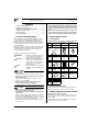
(2) Select the desired MODE NO. with the “ ” button.
(3) Push the “ ” button and select the FIRST CODE NO..
(4) Push the “ ” button and select the SECOND CODE
NO..
(5) Push the“ ”button and the present settings
are set.
(6) Push the “ ” button to quit the FIELD SET
MODE and return to the normal display.
(Example) If the time to clean air filter is set to “Filter Con-
tamination-Heavy”, set Mode No. to “10”, FIRST
CODE NO. to "0", and SECOND CODE NO. to
“02”.
NOTE
The SECOND CODE NO. is factory set to "01". However, for the
following cases it is set to "02".
• Air Flow Direction Range Setting
Do not use any settings not listed in the table.
For group control with a wireless remote controller, initial set-
tings for all the indoor units of the group are equal. (For group
control, refer to the installation manual attached to the indoor
unit for group control.)
6. TEST OPERATION
• Perform test operation according to the instructions in the
installation manual attached to the indoor unit.
• After refrigerant piping, drain piping, and electric wiring,
operate according to the table to protect the unit.
CAUTION
1. Refer to a malfunction code in the installation manual
attached to the outdoor unit if it does not operate.
2. Refer to the installation manual attached to the outdoor unit
for individual operation system types.
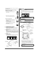
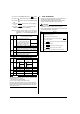
MODE
NO.
FIRST
CODE
NO.
DESCRIPTION OF SETTING
10
0
Filter Contamination-Heavy/Light
(Setting for spacing time of display
time to clean air filter) (Setting for
when filter contamination is heavy,
and spacing time of display time to
clean air filter is to be halved)
Long-life type
Standard type
1 Long-life filter type (Setting of filter sign indication time)
3
Spacing time of display time to clean air filter count
(Setting for when the filter sign is not to be displayed)
12
(VRV
system)
1
ON/OFF input from outside (Set to enable starting/
stopping from remote.)
2
Thermostat differential changeover (Set when using
remote controller thermostat sensor.)
13 4 Air Flow Direction Range Setting
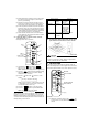
MODE
NO.
FIRST
CODE
NO.
SECOND CODE NO. NOTE)
01 02 03
10
0Light
Approx.
2,500 hours
Heavy
Approx.
1,250 hours
—
Approx. 200
hours
Approx. 100
hours
1 Long-life filter — —
3 Display Do not display —
12
(VRV
system)
1 Forced OFF input ON/OFF —
22°F 1°F —
13 4 Upper Normal Lower
MODE
UP
DOWN
RESERVE
TEST
Order Operation
(1) Open gas side stop valve.
(2) Open liquid side stop valve.
(3) Electrify crank case heater for 6 hours.
(4)
Set to cooling with the remote controller and push “ ”
button to start operation.
(5)
Push“ ”button twice and operate in TEST OPERA-
TION MODE for 3 minutes.
(6)
Push“ ”button and confirm its operation.
(7)
Push“ ”button and operate normally.
(8) Confirm its function according to the operation manual.
ON/OFF
TEST
SWING
TEST