
Installation manual

4
(2) Pull the relay harness from the receiver (1) up to where
the clamp (10) meets the stopper, as shown above.
(Refer to (2) in drawing)
(3) Install the receiver (1) where the decoration corner
panel was. Proceed in the opposite order in which you
removed the corner panel. (Refer to (3) in drawing)
(4) Fit the relay harness under the tab on the decoration
panel and connect it to connector X24A on the indoor
unit PC board. Bundle the remaining harness with the
included clamp so that it does not droop or get pinched
in the suction grille. (Refer to (4) in drawing)
(5) Attach the lid to the indoor unit's control box and the
suction grille to the decoration panel. (Refer to installa-
tion manual of indoor unit.)
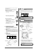
4-5. Setting the address of wireless remote controller
(It is factory set to “1”.)
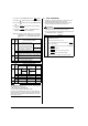
<Setting from the remote controller>
(1) Hold down the “ ” button and the “ ”
button for at least 4 seconds to get the FIELD SET
MODE. (Indicated in the display area in the figure at top.)
(2) Press the “ ” button and select a multiple setting
(A/b). Each time the button is pressed the display
switches between “A” and “b”.
(3) Press the “ ” button and “ ” button to set the
address.
Address can be set from 1 to 6, but set it from 1 to 3 and
to same address as the receiver. (The receiver does
not work with address from 4 to 6.)
(4) Press the “ ” button to enter the setting.
(5) Push the “ ” button to quit the FIELD SET
MODE and return to the normal display.
<Multiple settings A/b>
When the indoor unit is being operating by outside control (cen-
tral remote controller, etc.), it sometimes does not respond to
ON/OFF and temperature setting commands from this remote
controller. Check what setting the customer wants and make the
multiple setting as shown below.
4-6. Stick the Unit No. label on the air outlet of the decoration
panel and the back of the wireless remote controller.
CAUTION
Set the Unit No. of the receiver and the wireless remote con-
troller to be equal. If the settings differ, the signal from the
remote controller cannot be transmitted.
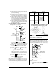
5. FIELD SETTING
If optional accessories are mounted on the indoor unit, the
indoor unit setting may have to be changed. Refer to the instruc-
tion manual (optional hand book ) for each optional accessory.
Procedure
(1) When in the normal mode, press the “ ” but-
ton for at least 4 seconds, and the FIELD SET MODE is
entered.
MODE
TIMER
RESERVE
CANCEL
DOWN
UP
TEST
SWING
FAN
TIME
TEMP
ON
OFF
SETTING
Mode
Address
Multiple setting
(3)
(2)
(4)
(1)
(5)
TEST
FAN
UP
DOWN
RESERVE
TEST
Remote controller Indoor unit
Multiple setting Remote control-
ler display
To control other
air conditions
and units
For other than
on left
A: Standard All items dis-
played.
Commands other
than ON/OFF
and temperature
setting accepted.
(1 LONG BEEP
or 3 SHORT
BEEPS emitted)
b: Multi System
Operations remain
displayed shortly
after execution
All commands accepted.
(2 SHORT BEEPS)
MODE
TIMER
RESERVE
CANCEL
DOWN
UP
TEST
SWING
FAN
TIME
TEMP
ON
OFF
SETTING
MODE NO.
SECOND CODE NO.
FIRST CODE NO.
FIELD SET MODE
(3)
(5)
(2)
(1) (6)
(4)
TEST