
Service Manual
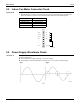
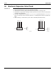
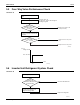
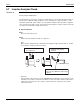
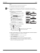
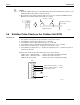
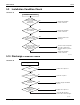
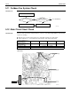
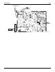
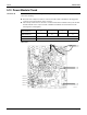
Table Of Contents

Check SiUS071735E
109 Service Diagnosis
5.13 Power Module Check
Check No.22 Check to make sure that the voltage between (+) and (–) of the power module is approximately
0 V before checking.
Disconnect the compressor harness connector from the outdoor unit PCB. To disengage the
connector, press the protrusion on the connector.
Follow the procedure below to measure resistance between the terminals of the power module
and the terminals of the compressor with a multimeter. Evaluate the measurement results
referring to the following table.
09/12 class
Positive terminal (+) of
digital multimeter
Power module
(+)
UVW Power module
(–)
UVW
Negative terminal (–) of
digital multimeter
UVW Power module
(+)
UVW Power module
(–)
Resistance is OK. several kΩ ~ several MΩ
Resistance is NG. 0 Ω or ∞
Pin 24: +
Pin 23: U
Pin 22: V
Pin 21: W
Pin 20: –
(R20703)