SiENBE07-618_C Service Manual Inverter Pair Duct Connected Type C-Series [Applied Models] z Inverter Pair: Cooling only z Inverter Pair: Heat Pump
SiENBE07-618_C Service Manual Inverter Pair Duct Connected Type C-Series [Applied Models] z Inverter Pair: Cooling only z Inverter Pair: Heat Pump
SiENBE07-618_C Inverter Pair Duct Connected Type C-Series zCooling Only Indoor Unit FDKS50CVMB FDKS60CVMB Outdoor Unit RKS50E2(3)V1B RKS60E2(3)V1B RKS50F2V1B RKS60F2(3)V1B RKS50G2V1B RXS50F2V1B RXS60F2(3)V1B RXS50G2V1B zHeat Pump Indoor Unit FDXS50CVMB FDXS60CVMB Outdoor Unit RXS50E2(3)V1B RXS60E2(3)V1B Table of Contents i
SiENBE07-618_C 1. Introduction .............................................................................................v 1.1 Safety Cautions ........................................................................................v 1.2 Used Icons .............................................................................................. ix Part 1 List of Functions ................................................................ 1 1. Functions.........................................................
SiENBE07-618_C Part 5 Operation Manual ............................................................. 43 1. System Configuration............................................................................44 2. Operation Manual..................................................................................45 2.1 2.2 2.3 2.4 2.5 2.6 Remote Control ......................................................................................45 Auto Dry Cool Heat Fan Operation .......................................
SiENBE07-618_C Part 7 Removal Procedure ........................................................ 101 1. Outdoor Unit........................................................................................102 1.1 1.2 1.3 1.4 1.5 1.6 1.7 1.8 Removal of Outer Panels .....................................................................102 Removal of Outdoor Fan / Fan Motor...................................................106 Removal of Electrical Box ..........................................................
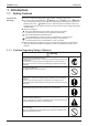
SiENBE07-618_C Introduction 1. Introduction 1.1 Safety Cautions Cautions and Warnings Be sure to read the following safety cautions before conducting repair work. The caution items are classified into “ Warning” and “ Caution”. The “ Warning” items are especially important since they can lead to death or serious injury if they are not followed closely. The “ Caution” items can also lead to serious accidents under some conditions if they are not followed.
Introduction SiENBE07-618_C Warning Be sure to wear a safety helmet, gloves, and a safety belt when working at a high place (more than 2 m). Insufficient safety measures may cause a fall accident. In case of R-410A refrigerant models, be sure to use pipes, flare nuts and tools for the exclusive use of the R-410A refrigerant. The use of materials for R-22 refrigerant models may cause a serious accident such as a damage of refrigerant cycle as well as an equipment failure.
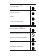
SiENBE07-618_C Introduction 1.1.2 Cautions Regarding Safety of Users Warning Be sure to use parts listed in the service parts list of the applicable model and appropriate tools to conduct repair work. Never attempt to modify the equipment. The use of inappropriate parts or tools may cause an electrical shock, excessive heat generation or fire. If the power cable and lead wires have scratches or deteriorated, be sure to replace them.
Introduction SiENBE07-618_C Warning Check to make sure that the power cable plug is not dirty or loose, then insert the plug into a power outlet securely. If the plug has dust or loose connection, it may cause an electrical shock or fire. Be sure to install the product correctly by using the provided standard For unitary type installation frame. only Incorrect use of the installation frame and improper installation may cause the equipment to fall, resulting in injury.
SiENBE07-618_C Introduction Caution Be sure to measure the insulation resistance after the repair, and make sure that the resistance is 1 MΩ or higher. Faulty insulation may cause an electrical shock. Be sure to check the drainage of the indoor unit after the repair. Faulty drainage may cause the water to enter the room and wet the furniture and floor. Do not tilt the unit when removing it. The water inside the unit may spill and wet the furniture and floor.
Introduction x SiENBE07-618_C
SiENBE07-618_C Part 1 List of Functions 1. Functions.................................................................................................
Functions SiENBE07-618_C Compressor Comfortable Airflow Comfort Control Operation Lifestyle Convenience { Operation Limit for Cooling (°CDB) –10 ~46 Operation Limit for Heating (°CWB) — –15 ~18 Air-Purifying Filter — — Photocatalytic Deodorizing Filter — — Air-Purifying Filter with Photocatalytic Deodorizing Function — — Category Health & Clean Functions PAM Control { { Oval Scroll Compressor — — Titanium Apatite Photocatalytic Air-Purifying Filter — — Swing Compressor {
Operation Limit for Cooling (°CDB) –10 ~46H –10 ~46 Operation Limit for Heating (°CWB) — –15 ~18 Compressor Comfortable Airflow Comfort Control Operation Lifestyle Convenience Inverter (with Inverter Power Control) PAM Control { { Oval Scroll Compressor — — FDXS50/60CVMB RXS50/60F2V1B { Functions FDKS50/60CVMB RKS50/60F2V1B FDXS50/60CVMB RXS50/60F2V1B { Category Basic Function Functions FDKS50/60CVMB RKS50/60F2V1B SiENBE07-618_C Air-Purifying Filter — — Photocatalytic Deodori
Compressor Comfortable Airflow Comfort Control Operation Lifestyle Convenience { { Operation Limit for Cooling (°CDB) –10 ~46H –10 ~46 Operation Limit for Heating (°CWB) — –15 ~18 Inverter (with Inverter Power Control) PAM Control { { Oval Scroll Compressor — — Air-Purifying Filter — — Photocatalytic Deodorizing Filter — — Air-Purifying Filter with Photocatalytic Deodorizing Function — — Titanium Apatite Photocatalytic Air-Purifying Filter — — Category Health & Clean Functi
SiENBE07-618_C Part 2 Specifications 1. Specifications ..........................................................................................6 1.1 Cooling Only.............................................................................................6 1.2 Heat Pump ...............................................................................................
Specifications SiENBE07-618_C 1. Specifications 1.1 Cooling Only 50 Hz, 230 V Models Indoor Units Outdoor Units Capacity Rated (Min. ~ Max.) Moisture Removal Running Current (Rated) Power Consumption Rated (Min. ~ Max.) Power Factor COP Rated (Min. ~ Max.) Liquid Piping Connections Gas Drain Heat Insulation Max. Interunit Piping Length Min. Interunit Piping Length Max.
SiENBE07-618_C Specifications 50 Hz, 230 V Models Indoor Units Outdoor Units Capacity Rated (Min. ~ Max.) Moisture Removal Running Current (Rated) Power Consumption Rated (Min. ~ Max.) Power Factor COP Rated (Min. ~ Max.) Liquid Piping Connections Gas Drain Heat Insulation Max. Interunit Piping Length Min. Interunit Piping Length Max.
Specifications SiENBE07-618_C 50 Hz, 230 V Models Indoor Units Outdoor Units Capacity Rated (Min. ~ Max.) Moisture Removal Running Current (Rated) Power Consumption Rated (Min. ~ Max.) Power Factor COP Rated (Min. ~ Max.) Liquid Piping Connections Gas Drain Heat Insulation Max. Interunit Piping Length Min. Interunit Piping Length Max.
SiENBE07-618_C 1.2 Specifications Heat Pump 50 Hz, 230 V Indoor Units Models Capacity Rated (Min. ~ Max.) Moisture Removal Running Current (Rated) Power Consumption Rated (Min. ~ Max.) Power Factor COP Rated (Min. ~ Max.) Liquid Piping Connections Gas Drain Heat Insulation Max. Interunit Piping Length Min. Interunit Piping Length Max.
Specifications SiENBE07-618_C 50 Hz, 230 V Indoor Units Models Capacity Rated (Min. ~ Max.) Moisture Removal Running Current (Rated) Power Consumption Rated (Min. ~ Max.) Power Factor COP Rated (Min. ~ Max.) Liquid Piping Connections Gas Drain Heat Insulation Max. Interunit Piping Length Min. Interunit Piping Length Max.
SiENBE07-618_C Specifications 50 Hz, 230 V Indoor Units Models Capacity Rated (Min. ~ Max.) Moisture Removal Running Current (Rated) Power Consumption Rated (Min. ~ Max.) Power Factor COP Rated (Min. ~ Max.) Liquid Piping Connections Gas Drain Heat Insulation Max. Interunit Piping Length Min. Interunit Piping Length Max.
SiENBE07-618_C Part 3 Printed Circuit Board Connector Wiring Diagram 1. Printed Circuit Board Connector Wiring Diagram..................................13 1.1 Indoor Unit..............................................................................................13 1.2 Outdoor Unit ...........................................................................................
SiENBE07-618_C Printed Circuit Board Connector Wiring Diagram 1. Printed Circuit Board Connector Wiring Diagram 1.
Printed Circuit Board Connector Wiring Diagram PCB Detail SiENBE07-618_C PCB (1): Control PCB FU1 S1 H2 H1 H3 V1 GND S7 S21 S26 LED A JA JB JC S32 2P131149-1 PCB (2): Display PCB S1 LED3 LED2 RTH1 LED1 SW1 2P084375-1 14 Printed Circuit Board Connector Wiring Diagram
SiENBE07-618_C 1.
Printed Circuit Board Connector Wiring Diagram PCB Detail SiENBE07-618_C PCB (1): Main PCB AC1 E1 E2 FU2 (3.15A) V3 V11 FU1 (30A) V2 HR1 V6 HR2 AC2 S10 S101 V5 S80 S90 S20 S40 S70 S51 FU3 (3.
SiENBE07-618_C Part 4 Function and Control 1. Main Functions......................................................................................18 1.1 1.2 1.3 1.4 1.5 1.6 1.7 1.8 1.9 1.10 Temperature Control ..............................................................................18 Frequency Principle................................................................................18 Fan Speed Control for Indoor Units........................................................20 Program Dry Operation ..
Main Functions SiENBE07-618_C 1. Main Functions 1.1 Temperature Control Definitions of Temperatures The definitions of temperatures are classified as following.
SiENBE07-618_C Drawing of Inverter Main Functions The following drawing shows a schematic view of the inverter principle: Refrigerant circulation rate (high) AC power DC power high speed Amount of heat exchanged air (large) Amount of heat exchanged air (small) high f low f Amount of heat exchanged air (large) Amount of heat exchanged air (small) low speed freq= 50 Hz constant 60 Hz freq=variable capacity= variable Refrigerant circulation rate (low) (R2812) Inverter Features The inverter pro
Main Functions 1.3 SiENBE07-618_C Fan Speed Control for Indoor Units Outline Phase control and fan speed control contains 9 steps: LLL, LL, SL, L, ML, M, MH, H, and HH. The airflow rate can be automatically controlled depending on the difference between the room thermistor temperature and the target temperature. This is done through phase control and Hall IC control. For more information about Hall IC, refer to the troubleshooting for fan motor on page 64.
SiENBE07-618_C 1.4 Main Functions Program Dry Operation Outline Program dry operation removes humidity while preventing the room temperature from lowering. Since the microcomputer controls both the temperature and airflow rate, the temperature adjustment and fan adjustment buttons are inoperable in this mode. Detail The microcomputer automatically sets the temperature and airflow rate.
Main Functions 1.5 Outline Detail SiENBE07-618_C Automatic Operation Automatic Cooling / Heating Function When the AUTO mode is selected with the remote control, the microcomputer automatically determines the operation mode as cooling or heating according to the room temperature and the set temperature at start-up, and automatically operates in that mode. The unit automatically switches the operation mode to maintain the room temperature at the set temperature.
SiENBE07-618_C 1.6 Main Functions Thermostat Control Thermostat control is based on the difference between the room thermistor temperature and the target temperature. Thermostat OFF Condition The temperature difference is in the zone A. Thermostat ON Condition The temperature difference returns to the zone C after being in the zone A. The system resumes from defrost control in any zones except A. The operation turns on in any zones except A.
Main Functions 1.7 SiENBE07-618_C NIGHT SET Mode Outline When the OFF timer is set, the NIGHT SET Mode is automatically activated. The NIGHT SET Mode keeps the airflow rate setting. Detail The NIGHT SET Mode continues operation at the target temperature for the first one hour, then automatically raises the target temperature slightly in the case of cooling, or lowers it slightly in the case of heating.
SiENBE07-618_C 1.8 Main Functions HOME LEAVE Operation Outline HOME LEAVE operation is a function that allows you to record your favorite set temperature and airflow rate. You can start your favorite operation mode simply by pressing the [HOME LEAVE] button on the remote control. Detail 1. Start of Function The function starts when the [HOME LEAVE] button is pressed in cooling mode, heating mode (including POWERFUL operation), or while the operation is stopped.
Main Functions 1.9 SiENBE07-618_C Inverter POWERFUL Operation Outline In order to exploit the cooling and heating capacity to full extent, operate the air conditioner by increasing the indoor fan rotating speed and the compressor frequency. Detail When POWERFUL button is pressed, the fan speed and target temperature are converted to the following states for 20 minutes.
SiENBE07-618_C Main Functions 1.10 Other Functions 1.10.1 Hot-Start Function In order to prevent the cold air blast that normally comes when heating operation is started, the temperature of the indoor heat exchanger is detected, and either the airflow is stopped or is made very weak thereby carrying out comfortable heating of the room. *The cold air blast is also prevented using a similar control when the defrosting operation is started or when the thermostat is turned ON. 1.10.
Function of Thermistor SiENBE07-618_C 2. Function of Thermistor A C Four way valve B Compressor (R11582) A Outdoor Heat Exchanger Thermistor 1. The outdoor heat exchanger thermistor is used for controlling target discharge pipe temperature. The system sets the target discharge pipe temperature according to the outdoor and indoor heat exchanger temperature, and controls the electronic expansion valve opening so that the target discharge pipe temperature can be obtained. 2.
SiENBE07-618_C Control Specification 3. Control Specification 3.1 Mode Hierarchy Outline There are two modes; the one is the normal operation mode and the other is the forced operation mode for installation and providing service. Detail For Cooling Only Model There are following modes; stop and cooling (including drying).
Control Specification 3.2 Outline SiENBE07-618_C Frequency Control Frequency is determined according to the difference between the room thermistor temperature and the target temperature. The function is explained as follows. 1. How to determine frequency 2. Frequency command from the indoor unit (Difference between the room thermistor temperature and the target temperature) 3. Frequency initial setting 4.
SiENBE07-618_C Control Specification 2. Determine upper limit frequency The minimum value is set as an upper limit frequency among the frequency upper limits of the following functions: Compressor protection, input current, discharge pipe temperature, heating peak-cut, freezeup protection, defrost. 3.
Control Specification 3.3 SiENBE07-618_C Controls at Mode Changing / Start-up 3.3.1 Preheating Operation Outline The inverter operation in open phase starts with the conditions of the outdoor temperature, the discharge pipe temperature, and the radiation fin temperature (internal temperature of PM1).
SiENBE07-618_C Control Specification 3.3.4 3-minute Standby Turning on the compressor is prohibited for 3 minutes after turning it off. (Except when defrosting.) 3.3.5 Compressor Protection Function When turning the compressor from OFF to ON, the upper limit of frequency is set as follows. (The function is not activated when defrosting.) (Hz) Frequency FCG 3 FCG 2 FCG 1 TCG1 TCG2 (Sec.) Time TCG3 (R10540) 3.
Control Specification 3.5 Outline SiENBE07-618_C Input Current Control The microcomputer calculates the input current during the compressor is running, and sets the frequency upper limit from the input current. In case of heat pump model, this control which is the upper limit control of the frequency takes priority to the lower limit of control of four way valve operation compensation.
SiENBE07-618_C 3.6 Control Specification Freeze-up Protection Control Outline During cooling operation, the signal sent from the indoor unit controls the operating frequency limitation and prevents freezing of the indoor heat exchanger. (The signal from the indoor unit is divided into zones.) Detail The operating frequency limitation is judged with the indoor heat exchanger temperature.
Control Specification 3.8 SiENBE07-618_C Outdoor Fan Control 1. Fan OFF delay when stopped The outdoor fan is turned OFF 60 seconds after the compressor stops. 2. Fan ON control to cool down the electrical box The outdoor fan is turned ON when the electrical box temperature is high while the compressor is OFF. 3. Fan OFF control while defrosting The outdoor fan is turned OFF while defrosting. 4. Fan ON/OFF control when operation starts / stops The outdoor fan is turned ON when the operation starts.
SiENBE07-618_C Control Specification 3.10 Defrost Control Outline Defrosting is carried out by the cooling cycle (reverse cycle). The defrosting time or outdoor heat exchanger temperature must be more than a certain value to finish. Detail Conditions for Starting Defrost The starting conditions is determined with the outdoor temperature and the outdoor heat exchanger temperature. The system is in heating operation. The compressor operates for 6 minutes.
Control Specification SiENBE07-618_C 3.11 Electronic Expansion Valve Control Detail The followings are the examples of control which function in each mode by the electronic expansion valve control. Control for abnormally high discharge pipe temperature The following items are included in the electronic expansion valve control. Electronic expansion valve is fully closed 1. Electronic expansion valve is fully closed when turning on the power. 2. Pressure equalizing control Open Control 1.
SiENBE07-618_C Control Specification 3.11.1 Fully Closing with Power ON The electronic expansion valve is initialized when turning on the power. The opening position is set and the pressure equalization is developed. 3.11.2 Pressure Equalization Control When the compressor is stopped, the pressure equalization control is activated. The electronic expansion valve opens, and develops the pressure equalization. 3.11.
Control Specification SiENBE07-618_C 3.11.6 Disconnection of the Discharge Pipe Thermistor Outline The disconnection of the discharge pipe thermistor is detected by comparing the discharge pipe temperature with the condensation temperature. If the discharge pipe thermistor is disconnected, the electronic expansion valve opens according to the outdoor temperature and the operation frequency, and operates for a specified time, and then stops.
SiENBE07-618_C Control Specification 3.12 Malfunctions 3.12.1 Sensor Malfunction Detection Sensor malfunction may occur in the thermistor. Relating to Thermistor Malfunction 1. Outdoor heat exchanger thermistor 2. Discharge pipe thermistor 3. Radiation fin thermistor 4. Outdoor temperature thermistor Relating to CT Malfunction When the output frequency is more than as malfunction. (Hz) 55 Hz and the input current is below A, it is judged (A) 0.5 3.12.
Control Specification SiENBE07-618_C 3.13 Forced Operation Mode Outline Forced operation mode includes only forced cooling. Detail Item Conditions Start Command frequency End Others 42 Forced Cooling 1) The outdoor unit is not abnormal and not in the 3-minute standby mode. 2) The outdoor unit is not operating. The forced operation is allowed when the above both conditions are met. Press the forced operation ON/OFF button (SW1) on the indoor unit for 5 seconds.
SiENBE07-618_C Part 5 Operation Manual 1. System Configuration............................................................................44 2. Operation Manual..................................................................................45 2.1 2.2 2.3 2.4 2.5 2.6 Operation Manual Remote Control ......................................................................................45 AUTO · DRY · COOL · HEAT · FAN Operation .....................................46 POWERFUL Operation ...................
System Configuration SiENBE07-618_C 1. System Configuration After the installation and test operation of the room air conditioner have been completed, it should be operated and handled as described below. Every user would like to know the correct method of operation of the room air conditioner, to check if it is capable of cooling (or heating) well, and to know a clever method of using it.
SiENBE07-618_C Operation Manual 2. Operation Manual 2.1 Remote Control Remote control 1 2 5 3 6 4 9 7 8 10 13 15 14 12 11 < ARC433B69, B76 > 1. Signal transmitter: • It sends signals to the indoor unit. 2. Display: • It displays the current settings. (In this illustration, each section is shown with all its displays ON for the purpose of explanation 3. HOME LEAVE button: HOME LEAVE operation 4. POWERFUL button: POWERFUL operation 5.
Operation Manual 2.2 SiENBE07-618_C Auto Dry Cool Heat Fan Operation The air conditioner operates with the operation mode of your choice. From the next time on, the air conditioner will operate with the same operation mode. To start operation 1. Press “MODE selector button” and select a operation mode. • • Each pressing of the button advances the mode setting in sequence. : AUTO : DRY : COOL : HEAT : FAN 4 2, 3 1 5 2. Press “ON/OFF button” . • The OPERATION lamp lights up.
SiENBE07-618_C Operation Manual To change the air flow rate setting 5. Press “FAN setting button”. DRY mode The air flow rate setting is not variable AUTO or COOL or HEAT or FAN mode Five levels of air flow rate setting from “ “ ” plus “ • ”“ “ to ” are available. Indoor unit quiet operation When the air flow is set to “ ”, the noise from the indoor unit will become quieter. Use this when making the noise quieter. The unit might lose power when the fan strength is set to a weak level.
Operation Manual 2.3 SiENBE07-618_C POWERFUL Operation POWERFUL operation quickly maximizes the cooling (heating) effect in any operation mode. You can get the maximum capacity To start POWERFUL operation 1. Press “POWERFUL button”. • POWERFUL operation ends in 20 minutes. Then the system automatically operates again with the settings which were used before POWERFUL operation. • When using POWERFUL operation, there are some functions which are not available. • “ ” is displayed on the LCD.
SiENBE07-618_C 2.4 Operation Manual OUTDOOR UNIT QUIET Operation OUTDOOR UNIT QUIET operation lowers the noise level of the outdoor unit by changing the frequency and fan speed on the outdoor unit. This function is convenient during night. To start OUTDOOR UNIT QUIET operation 1. Press “QUIET button”. • “ ” is displayed on the LCD. To cancel OUTDOOR UNIT QUIET operation 2. Press “QUIET button” again. • “ ” disappears from the LCD.
Operation Manual 2.5 SiENBE07-618_C HOME LEAVE Operation HOME LEAVE operation is a function which allows you to record your preferred temperature and air flow rate settings. To start HOME LEAVE operation 1. Press “HOME LEAVE button”. • “ ” is displayed on the LCD. • The HOME LEAVE lamp lights up. 1, 2 To cancel HOME LEAVE operation 2. Press “HOME LEAVE button” again. • The HOME LEAVE lamp goes off. • “ ” disappears from the LCD.
SiENBE07-618_C Operation Manual What’s the HOME LEAVE operation Is there a set temperature and air flow rate which is most comfortable, a set temperature and air flow rate which you use the most? HOME LEAVE operation is a function that allows you to record your favorite set temperature and air flow rate. You can start your favorite operation mode simply by pressing the HOME LEAVE button on the remote control. This function is convenient in the following situations. Useful in these cases 1.
Operation Manual 2.6 SiENBE07-618_C TIMER Operation Timer functions are useful for automatically switching the air conditioner on or off at night or in the morning. You can also use OFF TIMER and ON TIMER in combination. To use OFF TIMER operation • Check that the clock is correct. If not, set the clock to the present time. 1. Press “OFF TIMER button”. 0:00 is displayed. blinks. 2. Press “TIMER Setting button” until the time setting reaches the point you like.
SiENBE07-618_C Operation Manual To use ON TIMER operation • Check that the clock is correct. If not, set the clock to the present time. 1. Press “ON TIMER button”. • 6:00 is displayed. • “ ”blinks. 2. Press “TIMER Setting button” until the time setting reaches the point you like. • Every pressing of either button increases or decreases the time setting by 10 minutes. Holding down either button changes the setting rapidly. 3. Press “ON TIMER button” again. • The TIMER lamp lights up..
SiENBE07-618_C Part 6 Service Diagnosis 1. Caution for Diagnosis............................................................................55 1.1 Troubleshooting with LED ......................................................................55 2. Problem Symptoms and Measures .......................................................56 3. Service Check Function ........................................................................57 4. Troubleshooting ......................................................
SiENBE07-618_C Caution for Diagnosis 1. Caution for Diagnosis 1.1 Troubleshooting with LED Indoor Unit The operation lamp blinks when any of the following errors is detected. 1. When a protection device of the indoor unit or the outdoor unit is activated, or when the thermistor malfunctions. 2. When a signal transmission error occurs between the indoor unit and the outdoor units. In either case, conduct the diagnostic procedure described in the following pages.
Problem Symptoms and Measures SiENBE07-618_C 2. Problem Symptoms and Measures Symptom Check Item The units does not operate. Check the power supply. Check the type of the indoor units. Check the outdoor temperature. Details of Measure Check to make sure that the rated voltage is supplied. Check to make sure that the indoor unit type is compatible with the outdoor unit.
SiENBE07-618_C Service Check Function 3. Service Check Function Check Method 1 1. When the timer cancel button is held down for 5 seconds, “00” indication appears on the temperature display section. ON CANCEL TIMER CANCEL button OFF TIMER < ARC433 Series > (R11506) 2. Press the timer cancel button repeatedly until a long beep sounds. The code indication changes in the sequence shown below. No. 1 2 3 4 5 6 7 8 9 10 11 Note: Service Diagnosis Code 00 U4 F3 E6 L5 A6 E5 F6 C9 U0 E7 No.
Service Check Function SiENBE07-618_C Check Method 2 1. Press the center of the TEMP button and the MODE button at the same time. (R4272) The figure of the ten’s place blinks. (R4273) 2. Press the TEMPs or t button and change the figure until you hear the sound of “beep” or “pi pi”. (R4274) 3. Diagnose by the sound. H“pi” : The figure of the ten’s place does not accord with the error code. H“pi pi” : The figure of the ten’s place accords with the error code but the one’s not.
SiENBE07-618_C Service Check Function 5. Press the TEMPs or t button and change the figure until you hear the sound of “beep”. (R4277) 6. Diagnose by the sound. H“pi” : The figure of the ten’s place does not accord with the error code. H“pi pi” : The figure of the ten’s place accords with the error code but the one’s not. H“beep” : The both figures of the ten’s and one’s place accord with the error code. 7. Determine the error code. The figures indicated when you hear the “beep” sound are error code.
Troubleshooting SiENBE07-618_C 4. Troubleshooting 4.
SiENBE07-618_C 4.2 Troubleshooting Indoor Unit PCB Abnormality Remote Control Display A1 Method of Malfunction Detection Evaluation of zero-cross detection of power supply by the indoor unit PCB. Malfunction Decision Conditions There is no zero-cross detection in approximately 10 seconds.
Troubleshooting 4.3 SiENBE07-618_C Freeze-up Protection Control or Heating Peak-cut Control Remote Control Display A5 Method of Malfunction Detection Freeze-up protection control During cooling operation, the freeze-up protection control (operation halt) is activated according to the temperature detected by the indoor heat exchanger thermistor.
SiENBE07-618_C Troubleshooting Troubleshooting Be sure to turn off the power switch before connecting or disconnecting connectors, or parts may be damaged. Caution Check No.06 Refer to P.96 Check the air passage. Is there any short circuit? YES Provide sufficient air passage. NO Check the air filter. Is it very dirty? YES Clean the air filter. NO Check the dust accumulation on the indoor heat exchanger. Is it very dirty? YES Clean the indoor heat exchanger. NO Check No.
Troubleshooting 4.4 SiENBE07-618_C Fan Motor (AC motor) or Related Abnormality Remote Control Display A6 Method of Malfunction Detection The rotation speed is detected by the Hall IC while the fan motor is operating. The rotation speed determines the error. Malfunction Decision Conditions The detected rotation speed does not reach the demanded rotation speed of the target tap, and is less than 50% of the maximum fan motor rotation speed.
SiENBE07-618_C 4.5 Troubleshooting Thermistor or Related Abnormality (Indoor Unit) Remote Control Display C4, C9 Method of Malfunction Detection The temperatures detected by the thermistors determine thermistor errors. Malfunction Decision Conditions The thermistor input is more than 4.96 V or less than 0.04 V during compressor operation. Supposed Causes Disconnection of connector Defective thermistor Defective indoor unit PCB Troubleshooting Caution Check No.06 Refer to P.
Troubleshooting 4.6 SiENBE07-618_C Signal Transmission Error (between Indoor Unit and Outdoor Unit) Remote Control Display U4 Method of Malfunction Detection The data received from the outdoor unit checked whether it is normal. Malfunction Decision Conditions The data sent from the outdoor unit cannot be received normally, or the content of the data is abnormal. Supposed Causes Wiring error Breaking of the connection wires between the indoor and outdoor units (wire No.
SiENBE07-618_C 4.7 Troubleshooting Unspecified Voltage (between Indoor Unit and Outdoor Unit) Remote Control Display UA Method of Malfunction Detection The supply power is detected for its requirements (different from pair type and multi type) by the indoor / outdoor transmission signal. Malfunction Decision Conditions The pair type and multi type are interconnected.
Troubleshooting 4.8 SiENBE07-618_C Outdoor Unit PCB Abnormality Remote Control Display E1 Method of Malfunction Detection Detection within the program of the microcomputer Malfunction Decision Conditions The program of the microcomputer is in abnormal running order.
SiENBE07-618_C 4.9 Troubleshooting OL Activation (Compressor Overload) Remote Control Display E5 Method of Malfunction Detection A compressor overload is detected through compressor OL. Malfunction Decision Conditions If the error repeats twice, the system is shut down. Reset condition: Continuous run for about 60 minutes without any other error ∗ The operating temperature condition is not specified.
Troubleshooting SiENBE07-618_C 4.10 Compressor Lock Remote Control Display E6 Method of Malfunction Detection A compressor lock is detected by checking the compressor running condition through the position detection circuit. Malfunction Decision Conditions Judging from the current waveform generated when high-frequency voltage is applied to the compressor. If the error repeats 16 times, the system is shut down.
SiENBE07-618_C Troubleshooting 4.11 DC Fan Lock Remote Control Display E7 Method of Malfunction Detection An error is determined with the high-voltage fan motor rotation speed detected by the Hall IC. Malfunction Decision Conditions The fan does not start in 30 seconds even when the fan motor is running. If the error repeats 16 times, the system is shut down.
Troubleshooting SiENBE07-618_C 4.12 Input Overcurrent Detection Remote Control Display E8 Method of Malfunction Detection An input overcurrent is detected by checking the input current value being detected by CT with the compressor running. Malfunction Decision Conditions The following CT input with the compressor running continues for 2.5 seconds.
SiENBE07-618_C Troubleshooting 4.13 Four Way Valve Abnormality Remote Control Display EA Method of Malfunction Detection The room temperature thermistor, the indoor heat exchanger thermistor, the outdoor temperature thermistor, and the outdoor heat exchanger thermistor are checked if they function within their normal ranges in each operation mode. Malfunction Decision Conditions A following condition continues over 1 minute after operating for 10 minutes. Cooling / Dry (room thermistor temp.
Troubleshooting SiENBE07-618_C Troubleshooting Caution Check No.05 Refer to P.95 Check No.06 Refer to P.96 Check No.11 Refer to P.98 Be sure to turn off the power switch before connecting or disconnecting connectors, or parts may be damaged. Four way valve coil disconnected (loose)? YES Correct it. NO Harness out of connector? YES Reconnect it. NO Check the continuity of the four way valve coil and harness. Disconnect the harness from the connector.
SiENBE07-618_C Troubleshooting 4.14 Discharge Pipe Temperature Control Remote Control Display F3 Method of Malfunction Detection An error is determined with the temperature detected by the discharge pipe thermistor. Malfunction Decision Conditions If the temperature detected by the discharge pipe thermistor rises above compressor stops. The error is cleared when the temperature is dropped below °C. (°C) 110 °C, the (°C) 95 If the error repeats 6 times, the system is shut down.
Troubleshooting SiENBE07-618_C 4.15 High Pressure Control in Cooling Remote Control Display F6 Method of Malfunction Detection High-pressure control (operation half, frequency drop, etc.) is activated in cooling mode if the temperature sensed by the outdoor heat exchanger thermistor exceeds the limit. Malfunction Decision Conditions The temperature sensed by the outdoor heat exchanger thermistor rises above about 60°C. The error is cleared when the temperature drops below about 50°C.
SiENBE07-618_C Troubleshooting 4.16 Compressor System Sensor Abnormality Remote Control Display H0 Method of Malfunction Detection The system checks the supply voltage and the DC voltage before the compressor starts. The system checks the compressor current right after the compressor starts. Malfunction Decision Conditions The supply voltage and the DC voltage is obviously low or high. The compressor current does not run when the compressor starts.
Troubleshooting SiENBE07-618_C 4.17 Position Sensor Abnormality Remote Control Display H6 Method of Malfunction Detection A compressor start-up failure is detected by checking the compressor running condition through the position detection circuit. Malfunction Decision Conditions If the error repeats 8 times, the system is shut down.
SiENBE07-618_C Troubleshooting Troubleshooting Caution Be sure to turn off the power switch before connecting or disconnecting connectors, or parts may be damaged. Turn off the power. Check the power supply voltage. Voltage as rated? NO Correct the power supply. YES Check the connection. Electrical components or compressor harnesses connected as specified? NO Reconnect them as specified. YES Turn on the power. Check the electrolytic capacitor voltage.
Troubleshooting SiENBE07-618_C 4.18 CT or Related Abnormality Remote Control Display H8 Method of Malfunction Detection A CT or related error is detected by checking the compressor running frequency and CTdetected input current. Malfunction Decision Conditions The compressor running frequency is more than A. (Hz) 55 Hz, and the CT input current is below (A) 0.5 If the error repeats 4 times, the system is shut down.
SiENBE07-618_C Troubleshooting Troubleshooting Caution Check No.12 Refer to P.99 Be sure to turn off the power switch before connecting or disconnecting connectors, or parts may be damaged. Turn off the power and turn it on again. Start operation. ∗ Running current as shown at right with relay cable 1 or 2? YES Current (guideline) NO Check No. 12 Check the capacitor voltage. Rising with increasing frequency 2 sec 320 ± 50 VDC? Replace the outdoor unit PCB.
Troubleshooting SiENBE07-618_C 4.19 Thermistor or Related Abnormality (Outdoor Unit) Remote Control Display H9, J3, J6, P4 Method of Malfunction Detection This type of error is detected by checking the thermistor input voltage to the microcomputer. A thermistor error is detected by checking the temperature sensed by each thermistor. Malfunction Decision Conditions The thermistor input voltage is above 4.96 V or below 0.04 V with the power on.
SiENBE07-618_C Troubleshooting Check No.06 Refer to P.96 Troubleshooting In case of “H9” “J3” “J6” Caution Be sure to turn off the power switch before connecting or disconnecting connectors, or parts may be damaged. Turn on the power again. Error displayed again on remote control? NO Reconnect the connectors or thermistors. YES Check No. 06 Check the thermistor resistance value. Normal? NO J3 error: the discharge pipe temperature is YES lower than the heat exchanger temperature.
Troubleshooting SiENBE07-618_C 4.20 Electrical Box Temperature Rise Remote Control Display L3 Method of Malfunction Detection An electrical box temperature rise is detected by checking the radiation fin thermistor with the compressor off. Malfunction Decision Conditions With the compressor off, the radiation fin temperature is above °C. The error is cleared when the radiation fin temperature drops below °C.
SiENBE07-618_C Troubleshooting Troubleshooting Check No.07 Refer to P.97 Check No.09 Refer to P.98 Caution Be sure to turn off the power switch before connecting or disconnecting connectors, or parts may be damaged. Turn off the power and turn it on again. Error again or outdoor fan activated? WARNING To cool the electrical components, the outdoor fan starts when the radiation fin temperature rises above °C and stops when it drops below °C. YES NO Check the radiation fin temperature.
Troubleshooting SiENBE07-618_C 4.21 Radiation Fin Temperature Rise Remote Control Display L4 Method of Malfunction Detection A radiation fin temperature rise is detected by checking the radiation fin temperature with the compressor on. Malfunction Decision Conditions The radiation fin temperature with the compressor on is above °C. The error is cleared when the radiation fin temperature drops below °C. (°C) (°C) 105 99 If the error repeats, the system is shut down.
SiENBE07-618_C Troubleshooting Troubleshooting Caution Check No.07 Refer to P.97 Be sure to turn off the power switch before connecting or disconnecting connectors, or parts may be damaged. Turn off the power and turn it on again to start the system. Check No.09 Refer to P.98 Error displayed again? YES NO Has PCB been replaced? °C? YES NG OK Radiation fin dirty? Check if the silicon grease applied properly on the radiation fin. If not, apply it (∗). (See Note.
Troubleshooting SiENBE07-618_C 4.22 Output Overcurrent Detection Remote Control Display L5 Method of Malfunction Detection An output overcurrent is detected by checking the current that flows in the inverter DC section. Malfunction Decision Conditions A position signal error occurs while the compressor is running. A speed error occurs while the compressor is running. An output overcurrent signal is fed from the output overcurrent detection circuit to the microcomputer.
SiENBE07-618_C Troubleshooting Troubleshooting Caution Check No.07 Refer to P.97 Be sure to turn off the power switch before connecting or disconnecting connectors, or parts may be damaged. ∗ An output overcurrent signal may result from wrong internal wiring. If the wires have been disconnected and reconnected and the system is interrupted by an output overcurrent, take the following procedure. Check No. 07 Check the installation condition. Check No.08 Refer to P.
Troubleshooting SiENBE07-618_C 4.23 Refrigerant Shortage Remote Control Display Method of Malfunction Detection U0 Refrigerant shortage detection I: Refrigerant shortage is detected by checking the input current value and the compressor output frequency. If the refrigerant is short, the input current is smaller than the normal value. Refrigerant shortage detection II: Refrigerant shortage is detected by checking the discharge pipe temperature and the opening of the electronic expansion valve.
SiENBE07-618_C Troubleshooting Troubleshooting Caution Check No.04 Refer to P.94 Check No.06 Refer to P.96 Be sure to turn off the power switch before connecting or disconnecting connectors, or parts may be damaged. Any thermistor disconnected? NO Stop valve closed? YES Replace them in position. * Discharge pipe thermistor * Indoor or outdoor heat exchanger thermistor * Room temperature thermistor * Outdoor temperature thermistor YES Open the stop valve. NO Check for refrigerant shortage.
Troubleshooting SiENBE07-618_C 4.24 Low-voltage Detection or Over-voltage Detection Remote Control Display Method of Malfunction Detection U2 Low-voltage detection: An abnormal voltage drop is detected by the DC voltage detection circuit. Over-voltage detection: An abnormal voltage rise is detected by the over-voltage detection circuit. Malfunction Decision Conditions Low-voltage detection: The voltage detected by the DC voltage detection circuit is below 150 V.
SiENBE07-618_C Troubleshooting 4.25 Signal Transmission Error (on Outdoor Unit PCB) Remote Control Display U7 Method of Malfunction Detection Communication error between microcomputer mounted on the main microcomputer and PM1. Malfunction Decision Conditions The abnormality is determined when the data sent from the PM1 can not be received for 9 seconds. The error counter is reset when the data from the PM1 can be successfully received.
Check SiENBE07-618_C 5. Check 5.1 How to Check 5.1.1 Electronic Expansion Valve Check Check No.04 Conduct the followings to check the electronic expansion valve (EV). 1. Check to see if the EV connector is correctly connected to the PCB. 2. Turn the power off and on again, and check to see if the EV generate latching sound. 3. If the EV does not generate latching sound in the above step 2, disconnect the connector and check the continuity using a tester. 4.
SiENBE07-618_C Check 5.1.2 Four Way Valve Performance Check Check No.05 Turn off the power and turn it on again. Start heating operation. S80 voltage at 220 - 240 VAC with compressor on? (Fig. 1) ∗ Four way valve coil Cooling / Dry : No continuity Heating : Continuity NO Replace the outdoor unit PCB. YES Disconnect the four way valve coil from the connector and check the continuity. Four way valve coil resistance at 1000 ~ 2000 Ω? NO Replace the four way valve coil.
Check SiENBE07-618_C 5.1.3 Thermistor Resistance Check Check No.06 Disconnect the connectors of the thermistors from the PCB, and measure the resistance of each thermistor using tester. The relationship between normal temperature and resistance is shown in the table and the graph below. Thermistor R25°C = 20 kΩ, B = 3950 Temperature (°C) –20 –15 –10 –5 0 5 10 15 20 25 30 35 40 45 50 211.0 (kΩ) 150.0 116.5 88.0 67.2 51.9 40.0 31.8 25.0 20.0 16.0 13.0 10.6 8.7 7.
SiENBE07-618_C Check 5.1.4 Installation Condition Check Check No.07 Installation condition check Check the allowable dimensions of the air suction and discharge area. NG Change the installation location or direction. OK Is the discharged air short-circuited? YES Change the installation location or direction. NO Is the outdoor heat exchanger very dirty? NO Is the airflow blocked by obstacles or winds blowing in the opposite direction? YES YES NO Clean the outdoor heat exchanger.
Check SiENBE07-618_C 5.1.6 Outdoor Fan System Check Check No.09 DC motor Check the outdoor fan system. Fan motor lead wire connector disconnected? NO Outdoor fan running? YES Outdoor fan system is functioning. YES Reconnect the connector. NO Go to Check No. 15. (R7159) 5.1.7 Power Supply Waveforms Check Check No.10 Measure the power supply waveform between No.1 and No.2 on the terminal board, and check the waveform disturbance. Check to see if the power supply waveform is a sine wave. (Fig.
SiENBE07-618_C Check 5.1.9 Capacitor Voltage Check Check No.12 Before this check, be sure to check the main circuit for short circuit. With the circuit breaker still on, measure the voltage according to the drawing of the model in question. Be careful never to touch any live parts. Multimeter (DC voltage range) Reactor lead wire OL lead wire Thermistor lead wire Four way valve lead wire Compressor lead wire Electronic expansion valve lead wire Fan motor lead wire (R5222) 5.1.
Check SiENBE07-618_C 5.1.11 Rotation Pulse Input on the Outdoor Unit PCB Check Check No.15 Make sure that the voltage of 320 ± 30 V is applied. 1. Set operation off and power off. Disconnect the connector S70. 2. Check that the voltage between the pins 4 - 7 is 320 VDC. 3. Check that the control voltage between the pins 3 - 4 is 15 VDC. 4. Check that the rotation command voltage between the pins 2 - 4 is 0 ~ 15 VDC. 5. Keep operation off and power off. Connect the connector S70. 6.
SiENBE07-618_C Part 7 Removal Procedure 1. Outdoor Unit........................................................................................102 1.1 1.2 1.3 1.4 1.5 1.6 1.7 1.8 Removal Procedure Removal of Outer Panels .....................................................................102 Removal of Outdoor Fan / Fan Motor...................................................106 Removal of Electrical Box ....................................................................110 Removal of PCB..............
Outdoor Unit SiENBE07-618_C 1. Outdoor Unit 1.1 Removal of Outer Panels Procedure Warning Be sure to wait for 10 minutes or more after turning off all power supplies before disassembling work. Procedure Step 1. Remove the panels. 1 Remove the 4 screws and lift the top panel. Points Top panel (R12283) Take care not to cut your finger by the fins of the outdoor heat exchanger. (R12315) 2 Slide the discharge grille upwards and remove it. Remove the 4 screws and remove the discharge grille.
SiENBE07-618_C Outdoor Unit Procedure Step Points The discharge grille has 4 hooks. 3 Remove the 6 screws of the front panel. Front panel (R12284) 4 Push the front panel and lift the shield plate to unfasten the hooks. Shield plate 1 Push the front panel. 2 Lift the shield plate upwards.
Outdoor Unit Procedure Step 5 SiENBE07-618_C Unfasten the left side hooks, and then the right side hook. Remove the front panel. Points Lift the front panel while pushing the left side panel inwards. Lift the front panel and unfasten the right side hook. When reassembling, fit the right side of the front panel first.
SiENBE07-618_C Outdoor Unit Procedure Step Points 2. Remove the stop valve cover. 1 Remove the screw of the stop valve cover. Stop valve cover (R5252) 2 Pull down the stop valve cover to unfasten the hooks and remove it. The stop valve cover has 6 hooks.
Outdoor Unit 1.2 SiENBE07-618_C Removal of Outdoor Fan / Fan Motor Procedure Warning Be sure to wait for 10 minutes or more after turning off all power supplies before disassembling work. Procedure Step 1. Remove the electrical box cover. 1 Remove the screw of the shield plate. Points Preparation Remove the top panel and the front panel according to the “Removal of Outer Panels”. Shield plate This procedure is not necessary to remove the outdoor fan only.
SiENBE07-618_C Outdoor Unit Procedure Step Points (R5258) 2. Remove the fan motor. 1 Disconnect the connector for the fan motor [S70]. [S70] (R5259) 2 Release the fan motor lead wire from the 7 hooks.
Outdoor Unit Procedure Step 3 SiENBE07-618_C Points The screw has reverse winding. Nut size: M6 Remove the washerfitted nut of the outdoor fan. 10 mm (R12236) Outdoor fan (R5262) When reassembling, align mark of the outdoor fan with D-cut section of the motor shaft. (R5263) 4 Remove the lower 2 screws from the fan motor first. 5 Then, remove the upper 2 screws. Be sure to remove the lower screws first.
SiENBE07-618_C Procedure Step 6 Outdoor Unit Points When reassembling, put the fan motor lead wire through the back of the fan motor (so as not to be entangled with the outdoor fan). Release the fan motor lead wire from the 2 hooks and pull the fan motor out.
Outdoor Unit 1.3 Removal of Electrical Box Procedure Warning Be sure to wait for 10 minutes or more after turning off all power supplies before disassembling work. Procedure Step 1 SiENBE07-618_C Points Remove the 2 screws of the shield plate. Preparation Remove the top panel and the front panel according to the “Removal of Outer Panels”. Shield plate (R5266) 2 Slide the shield plate upward to unfasten the 1 hook on the bottom left, and then remove the shield plate.
SiENBE07-618_C Procedure Step 4 Outdoor Unit Points Disconnect the 2 earth wires. Earth wires (R5269) 5 Remove the 3 screws of the right side panel. Right side panel (R5270) 6 Remove the screw of the electrical box.
Outdoor Unit Procedure Step 7 SiENBE07-618_C Unfasten the hooks and remove the right side panel. Points When reassembling, insert the 2 hooks of the lower part and the 1 hook of the upper back. Hook (R5272) Hooks 8 Disconnect the connectors of the front side. [S20]: electronic expansion valve coil [S40]: overload protector [S80]: four way valve coil [S90]: thermistors [S40] [S20] [S90] (R5273) [S80] (R5275) 9 112 Disconnect the relay connector for the compressor.
SiENBE07-618_C Procedure Step 10 Outdoor Unit Points Release the clamp of the compressor relay harness with pliers. Compressor relay harness (R5277) 11 Detach the clamp and release the thermistor lead wires from the hook. Hook Thermistor lead wire 12 Clamp (R5278) Remove the screw.
Outdoor Unit Procedure Step 13 SiENBE07-618_C Points Release the harness of the outdoor temperature thermistor from the hook. (R9403) 14 Lift and remove the electrical box.
SiENBE07-618_C 1.4 Removal of PCB Procedure Warning Be sure to wait for 10 minutes or more after turning off all power supplies before disassembling work. Procedure Step 1 Outdoor Unit Disconnect the connectors from the service monitor PCB [S52] [S102]. [S52] Points Preparation Remove the electrical box according to the “Removal of Electrical Box”. [S102] Service monitor PCB (R5280) 2 Detach the 4 clamps with pliers.
Outdoor Unit SiENBE07-618_C Procedure Step 4 Unfasten the hook on the right. 5 Open the terminal board. 6 Disconnect the harnesses. Points 1: Black 2: White 3: Red L1: Black L2: Brown N1: White N2: Blue L2 N2 1 2 3 7 Disconnect the 2 connectors for the reactor [HR1] [HR2].
SiENBE07-618_C Procedure Step 8 Outdoor Unit Points Remove the 3 screws of the main PCB. Main PCB (R5287) 9 Unfasten the 4 hooks. Hooks 10 Lift up and remove the main PCB. (R5288) Refer to page 16 for detail.
Outdoor Unit 1.5 Removal of Sound Blanket / Thermistors Procedure Warning Be sure to wait for 10 minutes or more after turning off all power supplies before disassembling work. Procedure Step 1 SiENBE07-618_C Points Remove the sound blanket (back). Sound blanket (back) 2 Remove the sound blanket (outer). Sound blanket (outer) Since the piping ports are torn easily, remove the sound blanket carefully. (R5293) 3 Remove the sound blanket (top upper).
SiENBE07-618_C Procedure Step 4 Outdoor Unit Remove the sound blanket (top lower). Points Sound blanket (top lower) (R11398) 5 Remove the sound blanket (inner). Sound blanket (inner) 6 (R5296) Be careful not to lose the clip for the thermistor. Release the discharge pipe thermistor. Clip (R12287) Discharge pipe thermistor 7 Cut the clamp and pull out the outdoor heat exchanger thermistor.
Outdoor Unit 1.6 SiENBE07-618_C Removal of Four Way Valve Procedure Warning Procedure Step 1 Be sure to wait 10 minutes or more after turning off all power supplies before disassembling work. Remove the screw and remove the four way valve coil. Points Four way valve Four way valve coil Warning Be careful not to get yourself burnt with the pipes and other parts that are heated by the gas brazing machine. Warning If the refrigerant gas leaks during work, ventilate the room.
SiENBE07-618_C 1.7 Removal of Electronic Expansion Valve Procedure Warning Be sure to wait for 10 minutes or more after turning off all power supplies before disassembling work. Procedure Step 1 Outdoor Unit Pull out the electronic expansion valve coil. Points Electronic expansion valve coil (R2737) 2 Remove the sheets of putty. Before working, make sure that the refrigerant gas is empty in the circuit. Be sure to apply nitrogen replacement when heating up the brazed part.
Outdoor Unit 1.8 Removal of Compressor Procedure Warning Be sure to wait for 10 minutes or more after turning off all power supplies before disassembling work. Procedure Step 1 SiENBE07-618_C Points Remove the terminal cover. Terminal cover (R5302) 2 Disconnect the lead wires of the compressor.
SiENBE07-618_C Outdoor Unit Procedure Step 3 Release the clamp with pliers to detach the compressor lead wires. 4 Remove the putty. Before working, make sure that the refrigerant gas is empty in the circuit. Be sure to apply nitrogen replacement when heating up the brazed part. 5 Heat up the brazed parts indicated by the arrows. Points Warning Be careful not to get yourself burnt with the pipes and other parts that are heated by the gas brazing machine.
Outdoor Unit Procedure Step 6 SiENBE07-618_C Points Remove the 2 nuts of the compressor. Cautions for restoration 1. Restore the piping by nonoxidation brazing. 2. It is required to prevent the carbonization of the oil inside the four way valve and the deterioration of the gaskets affected by heat. (Keep below 120°C.) For the sake of this, wrap the four way valve with wet cloth and provide water so that the cloth does not dry.
SiENBE07-618_C Part 8 Trial Operation and Field Settings 1. Trial Operation ....................................................................................126 2. Field Settings ......................................................................................127 2.1 When 2 Units are Installed in 1 Room..................................................127 2.2 Facility Setting Switch (cooling at low outdoor temperature)................128 2.3 Jumper and Switch Settings...............................
Trial Operation SiENBE07-618_C 1. Trial Operation Outline 1. Measure the supply voltage and make sure that it falls in the specified range. 2. Trial operation should be carried out in either cooling or heating mode. 3. Carry out the trial operation in accordance with the operation manual to ensure that all functions and parts, such as flap movement, are working properly. The air conditioner requires a small amount of power in its standby mode.
SiENBE07-618_C Field Settings 2. Field Settings 2.1 When 2 Units are Installed in 1 Room When 2 indoor units are installed in 1 room, 1 of the 2 pairs of indoor unit and infrared remote control can be set for different addresses. Both the indoor unit PCB and the infrared remote control need alteration. Indoor Unit PCB Cut the jumper JA on PCB. JA ADDRESS JB JC ADDRESS: JA 1 EXIST CUT 2 (R12240) Infrared remote control Cut the jumper J4.
Field Settings 2.2 SiENBE07-618_C Facility Setting Switch (cooling at low outdoor temperature) Outline For Cooling Only Model This function is limited only for facilities (the target of air conditioning is equipment (such as computer)). Never use it in a residence or office (the space where there is a human). Detail You can expand the operation range to –15°C by turning on the switch (SW4-B) on the service monitor PCB. If the outdoor temperature falls to –20°C or lower, the operation stops.
SiENBE07-618_C Application of Silicon Grease to a Power Transistor and a Diode Bridge 3. Application of Silicon Grease to a Power Transistor and a Diode Bridge Applicable Models All outdoor units using inverter type compressor for room air conditioner. When the printed circuit board (PCB) of an outdoor unit is replaced, it is required that silicon grease (*1) is certainly applied to the heat radiation part (the contact point to the radiation fin) of the power transistor and diode bridge.
SiENBE07-618_C Part 9 Appendix 1. Piping Diagrams..................................................................................131 1.1 Indoor Unit............................................................................................131 1.2 Outdoor Unit .........................................................................................132 2. Wiring Diagrams..................................................................................133 2.1 Indoor Unit...................................
SiENBE07-618_C Piping Diagrams 1. Piping Diagrams 1.1 Indoor Unit FDKS50/60CVMB, FDXS50/60CVMB INDOOR UNIT (6.4CuT) HEAT EXCHANGER FIELD PIPING (6.4CuT) SIROCCO FAN THERMISTOR ON HEAT EXCH. M FAN MOTOR ( FIELD PIPING ( CuT) CuT) REFRIGERANT FLOW COOLING HEATING FDXS50CVMB FDXS60CVMB FDKS50CVMB FDKS60CVMB 12.
Piping Diagrams 1.2 SiENBE07-618_C Outdoor Unit 1.2.1 Cooling Only RKS50/60E2(3)V1B, RKS50/60F2V1B, RKS50G2V1B, RKS60F3V1B OUTDOOR UNIT HEAT EXCHANGER 7.9CuT OUTDOOR AIR TEMPERATURE THERMISTOR 7.9CuT 7.9CuT 7.9CuT 7.9CuT CAPILLARY TUBE 1 7.9CuT 4.0CuT 7.9CuT 7.9CuT 4.0CuT 7.9CuT CAPILLARY TUBE 2 CAPILLARY TUBE 3 4.0CuT HEAT EXCHANGER THERMISTOR MUFFLER WITH FILTER 6.4CuT REFRIGERANT FLOW COOLING 6.4CuT 7.9CuT 4.0CuT CAPILLARY TUBE 4 M 6.4CuT 12.7CuT PROPELLER FAN 12.
SiENBE07-618_C Wiring Diagrams 2. Wiring Diagrams 2.1 Indoor Unit FDKS50/60CVMB, FDXS50/60CVMB X1M PCB1 PCB2 H1 F1U 3.15A V1TR LED LED LED S1 1 H1P H2P H3P S26 1 ( 10 2 RTH11 H3 3 6 S21 S1W SIGNAL RECEIVER ) 1 TRANSMISSION GND CIRCUIT S1 RED S7 10 1 2 S32 1 GRY BLK R1T C1 BRN BRN t° PPL INFRARED REMOTE CONTROL M 1~ indoor BLU R2T : C1 : F1U : PROTECTIVE EARTH CAPACITOR(M1F) 2 RED 3 1 2 3 outdoor N=2 GRN / YLW GRN / YLW FIELD WIRING.
Wiring Diagrams 2.2 SiENBE07-618_C Outdoor Unit 2.2.1 Cooling Only RKS50F2V1B, RKS50G2V1B L1R N E1 SA2 FU1 V2 AC1 30A Z2C E2 MRM10 BLK V6 8 6(P) PM1 RED BLU BRN ORG BLU BRN ORG WHT M1F M WHT M1C U X11A U V W 5 4 3 FU2 3.15A 1 S10 RED S70 1 + + + 7(N) 2 Z4C RED 9 V11 BLU WHT X2M 1 2 3 Z5C X12A 7 3.
SiENBE07-618_C Wiring Diagrams RKS60F3V1B L1R L Z2C N AC1 BRN X2M 1 2 3 E2 HR2 MRM10 1 6(P) 8 7(N) 9 V11 V6 Z5C FU3 7 3.15A + + + S70 1 MRM20 2 RED FU2 3.
Wiring Diagrams SiENBE07-618_C RXS50/60E2(3)V1B, RXS60F2V1B L1R GRN Z1C X1M POWER SUPPLY L N Z2C N AC1 E2 BLK WHT X2M 1 2 3 BLU 1 RED 8 9 V11 V6 S10 RED M M1C X11A U V W 5 4 3 M1F BLU BRN ORG WHT S70 1 + + + PM1 FU2 3.15A 1 6(P) 7(N) 2 Z4C 7 3.
Daikin Europe N.V. is approved by LRQA for its Quality Management System in accordance with the ISO9001 standard. ISO9001 pertains to quality assurance regarding design, development, manufacturing as well as to services related to the product. ISO14001 assures an effective environmental management system in order to help protect human health and the environment from the potential impact of our activities, products and services and to assist in maintaining and improving the quality of the environment.