
User`s manual

23
24
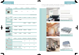
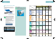
Outdoor unit
SpecificationsSpecifications
Specifications
Indoor unit
Duct-connected type
<
900/1,100 mm width
>
dB (A)
mm
kg
˚CDB
m
g/m
m
Notes: *1 The first value, to the left of slash, is the rated condition. The value to the right of the slash is the sound level when using outdoor unit quiet operation.
*2 For 230 V.
*3 Not including pipe length between water heater and outdoor unit.
FTKS35DVM
8.9 (314)
39/26/23
FTKS60FVM
16.2 (572)
45/36/33
FTKS50FVM
14.7 (519)
43/34/31
FTKS71FVM
17.4 (614)
46/37/34
FTKS25DVM
8.7 (307)
37/25/22
Liquid (flare)
Gas (flare)
Drain
m
3
/min (cfm)
dB (A)
mm
kg
mm
9
283 x 800 x 195
ø9.5
290 x 1,050 x 238
12
ø15.9ø12.7
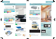
Wall-mounted type
FDKS50CVMB
12.0 (424)
37/33/31
FDKS35CAVMB
10.0 (353)
200 x 900 x 620
FDKS60CVMB
16.0 (565)
38/34/32
FDKS25CAVMB
9.5 (335)
Liquid (flare)
Gas (flare)
Drain
m
3
/min (cfm)
dB (A)
mm
kg
mm
Pa
27 30
35/31/29
25
ø9.5 ø12.7
3MWKS80KV1
1 phase, 220-240 V, 50 Hz
Ivory white
Hermetically sealed swing type
48/45
770 x 900 x 320
73
10 to 46*
2
60 (total)/25 (for one room)
15 (between water heater and outdoor unit)
20 (for 30 m or more)*
3
15 (between indoor and outdoor units)/7.5 (between indoor units)
7.5 (between water heater and outdoor unit)
Model name
Power supply
Casing colour
Compressor type
Sound levels*
1
Dimensions (H x W x D)
Machine weight
Operation range
Max. piping length
Necessity of additional charge
Max. installation
height difference
Model name
Power supply
Front panel colour
Airflow rates (H)
Sound levels (H/L/SL)
Fan speed
Temperature control
Dimensions (H x W x D)
Machine weight
Piping
connections
Heat insulation
1 phase, 230 V, 50 Hz
5 steps, quiet and automatic
Microcomputer control
ø6.4
VP20 (External Dia. 26/Internal Dia. 20)
Both liquid and gas pipes
40
Model name
Power supply
Airflow rates (H)
Sound levels (H/L/SL)*
Fan speed
Temperature control
Dimensions (H x W x D)
Machine weight
Piping
connections
Heat insulation
External static pressure
200 x 1,100 x 620
Duct-connected type
<
700 mm width
>
FDKS35EAVMBFDKS25EAVMB
Liquid (flare)
Gas (flare)
Drain
m
3
/min (cfm)
dB (A)
mm
kg
mm
Pa
1 phase, 230 V, 50 Hz
8.7 (307)
35/31/29
5 steps, quiet and automatic
Microcomputer control
200 x 700 x 620
21
ø6.4
ø9.5
VP20 (External Dia. 26/Internal Dia. 20)
Both liquid and gas pipes
30
Model name
Power supply
Airflow rates (H)
Sound levels (H/L/SL)*
Fan speed
Temperature control
Dimensions (H x W x D)
Machine weight
Piping
connections
Heat insulation
External static pressure
Note: * The operation sound level values represent those for rear-suction operation and an external static pressure of 30 Pa for FDKS-EA and 40 Pa for FDKS-C. Sound
level values for bottom-suction operation can be obtained by adding 6 dB (A) for FDKS-EA and 5 dB (A) for FDKS-C.
1 phase, 220-240 V/220-230 V, 50/60 Hz
White
ø6.4
5 steps, quiet and automatic
Microcomputer control
ø18.0
Both liquid and gas pipes
For indoor unit connection
For water heater connection
For indoor unit connection
For water heater connection
Storage water heater
L
kW
A
min.
mm
mm
mm
˚C
kPa
kPa/˚C
kg
TUR-75KVM
TUL-75KVM
75
(220 V) 2.5 / (230 V) 2.75 / (240 V) 3.0
(220 V) 11.4 / (230 V) 12 / (240 V) 12.5
86 (220 V)
78 (230 V)
71 (240 V)
1130
220-240 V/50 Hz 220-230 V/60 Hz
65
800
(Pressure) 1000 / (Temp) 99
3/4” /20 BSP
3/4” /20 BSP
3/4”-16 UNF (2A)
33
TUR-100KVM
TUL-100KVM
100
114 (220 V)
104 (230 V)
95 (240 V)
962
ø458
240
37
TUR-55KVM
TUL-55KVM
55
63 (220 V)
57 (230 V)
52 (240 V)
790
26
Model Number
Rated storage
Rated power
Rated electric current
Without airconditioners on,
time of hot water at 40˚C rise
by electric heater
Length A
Diameter B
C
Power
Temperature setting
Max. inlet water pressure
T&P relief valve set (pressure/temp)
Pipe sizes for inlet and outlet
Pipe size for safety valve
Refrigerant pipe size for inlet and outlet
Package weight
ø370
150
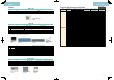
Diagram
Liquid (flare)
Gas (flare)
Drain
Compact multi flow ceiling-mounted cassette type
Note: * Anechoic chamber conversion value, measured according to JIS parameters and criteria. During operation these values are somewhat higher owing to ambient conditions.
Model name
Power supply
Airflow rate (H)
Sound level* (H/L)
Fan speed
Temperature control
Unit dimensions (H x W x D)
Machine weight
Piping
connections
Heat insulation
dB (A)
mm
kg
mm
Model
Colour
Dimensions (H x W x D)
Weight
mm
kg
Panel
(option)
FFQ35BV1B
10.0 (353)
32/25
FFQ50BV1B
12.0 (424)
36/27
FFQ60BV1B
15.0 (530)
41/32
FFQ25BV1B
9.0 (318)
29.5/24.5
1 phase, 220-240 V, 50 Hz
2 steps
Microcomputer control
286 x 575 x 575
17.5
ø6.4
VP20 (External Dia. 26/Internal Dia. 20)
Both liquid and gas pipes
BYFQ60B8W1
White
2.7
ø9.5 ø12.7
55 x 700 x 700
Measurement conditions
1. Data is based on the following conditions: indoor temp. 27°CDB, 19°CWB; outdoor temp. 35°CDB; piping length 7.5 m.
2. Sound levels are anechoic conversion values. These values are normally somewhat higher during actual operation as a result of ambient conditions.
m
3
/min (cfm)