
Specifications


SiBE12-519 Outdoor Unit
Removal Procedure 185
1.2 Removal of the PCB
Procedure Warning Be sure to wait 10 minutes or more after turning off all power
supplies before disassembling work.
Step
Procedure Points
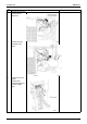
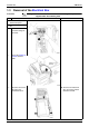
Disconnect the fan motor
lead wire.
The PCB is upside down for
the sake of quality
improvement.
Lead free soldering PbF is
adopted.
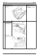
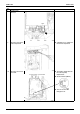
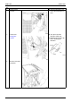
1. Remove the PCB.
1
The illustration shows
appearance of the PCB.
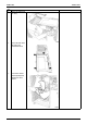
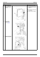
2
The illustration shows
arrangement of the
relaying connectors.
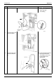
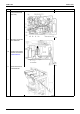
3
Disconnect the
connectors.
S20:electronic
expansion valve
(EVA)
S21:electronic
expansion valve
(EVB)
S70:fan motor
S80:four way valve
S90:thermistor
(discharge pipe,
outdoor air, heat
exchanger)
S91:thermistor (liquid
pipe, gas pipe)