SiBE 12 - 519 Inverter Multi for 2 Rooms D-Series [Applied Models] zInverter Multi : Cooling Only zInverter Multi : Heat Pump
SiBE12-519 Inverter Multi for 2 Rooms D-Series zCooling Only Outdoor Unit 2MKS40DVMB zHeat Pump Outdoor Unit 2MXS40DVMB Table of Contents Indoor Unit FTKS20D(2)VMW(L)(9) FTKS25D(2)VMW(L)(9) FTKS35D(2)VMW(L)(9) FTKS20CVMB(9) FTKS25CVMB(9)(8) FTKS35CVMB(9)(8) FDKS25CVMB FDKS35CVMB FLKS25BVMB FLKS35BVMB Indoor Unit FTXS20D(2)VMW(L)(9) FTXS25D(2)VMW(L)(9) FTXS35D(2)VMW(L)(9) FTXS20CVMB(9) FTXS25CVMB(9)(8) FTXS35CVMB(9)(8) FDXS25CVMB FDXS35CVMB FLXS25BVMB FLXS35BVMB i
SiBE12-519 1. Introduction .............................................................................................v 1.1 Safety Cautions ........................................................................................v Part 1 List of Functions ................................................................ 1 1. Cooling Only............................................................................................2 2. Heat Pump ................................................................
SiBE12-519 3.10 3.11 3.12 3.13 3.14 Defrost Control .......................................................................................61 Electronic Expansion Valve Control .......................................................62 Malfunctions ...........................................................................................66 Forced Operation Mode .........................................................................67 Additional Function...................................................
SiBE12-519 4.21 Over-voltage Detection.........................................................................167 4.22 Anti-icing Function in Other Rooms / Unspecified Voltage (between Indoor and Outdoor Units) ....................................................168 4.23 Outdoor Unit PCB Abnormality or Signal Transmission Circuit Abnormality..............................................169 5. Check ..................................................................................................170 5.
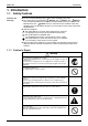
SiBE12-519 Introduction 1. Introduction 1.1 Safety Cautions Cautions and Warnings Be sure to read the following safety cautions before conducting repair work. Warning” and “ Caution”. The “ The caution items are classified into “ Warning” items are especially important since they can lead to death or serious injury if they are not followed closely. The “ Caution” items can also lead to serious accidents under some conditions if they are not followed.
Introduction SiBE12-519 Warning Do not repair the electrical components with wet hands. Working on the equipment with wet hands can cause an electrical shock. Do not clean the air conditioner by splashing water. Washing the unit with water can cause an electrical shock. Be sure to provide the grounding when repairing the equipment in a humid or wet place, to avoid electrical shocks. Be sure to turn off the power switch and unplug the power cable when cleaning the equipment.
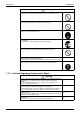
SiBE12-519 Introduction Warning Be sure to use an exclusive power circuit for the equipment, and follow the technical standards related to the electrical equipment, the internal wiring regulations and the instruction manual for installation when conducting electrical work. Insufficient power circuit capacity and improper electrical work can cause an electrical shock or fire. Be sure to use the specified cable to connect between the indoor and outdoor units.
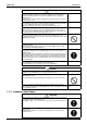
Introduction SiBE12-519 Warning Do not use a joined power cable or extension cable, or share the same power outlet with other electrical appliances, since it can cause an electrical shock, excessive heat generation or fire. Caution Check to see if the parts and wires are mounted and connected properly, and if the connections at the soldered or crimped terminals are secure. Improper installation and connections can cause excessive heat generation, fire or an electrical shock.
SiBE12-519 Part 1 List of Functions 1. Cooling Only............................................................................................2 2. Heat Pump ..............................................................................................
Cooling Only SiBE12-519 FTKS20-35D(2)VMW(L)(9) FTKS20-35CVMB(9)(8) { { Operation Limit for Cooling (°CDB) — — Air Purifying Filter with Bacteriostatic, Virustatic Functions — — Basic Function Operation Limit for Heating (°CWB) — — Photocatalytic Deodorizing Filter — — — Air Purifying Filter with Photocatalytic Deodorizing Function — { Titanium Apatite Photocatalytic Air-Purifying Filter { — { Functions PAM Control Compressor Comfortable Airflow Comfort Control Operation Lifes
Compressor Comfortable Airflow Comfort Control Operation Lifestyle Convenience Functions 2MKS40DVMB Basic Function { { { Operation Limit for Cooling (°CDB) — — 10 ~ 46 Photocatalytic Deodorizing Filter — { — Operation Limit for Heating (°CWB) — — — Air Purifying Filter with Photocatalytic Deodorizing Function — — — PAM Control — — { Titanium Apatite Photocatalytic Air-Purifying Filter — — — Functions FLKS25·35BVMB 2MKS40DVMB Inverter (with Inverter Power Control) Categ
Heat Pump SiBE12-519 FTXS20-35D(2)VMW(L)(9) FTXS20-35CVMB(9)(8) Inverter (with Inverter Power Control) { { Operation Limit for Cooling (°CDB) — — Air Purifying Filter with Bacteriostatic, Virustatic Functions — — Operation Limit for Heating (°CWB) — — Photocatalytic Deodorizing Filter — — Air Purifying Filter with Photocatalytic Deodorizing Function — { Titanium Apatite Photocatalytic Air-Purifying Filter { — { Functions Basic Function Compressor Comfortable Airflow Comfort Cont
Compressor Comfortable Airflow { { { Operation Limit for Cooling (°CDB) — — 10 ~ 46 Photocatalytic Deodorizing Filter — { — Operation Limit for Heating (°CWB) — — -10 ~ 15.
Heat Pump 6 SiBE12-519 List of Functions
SiBE12-519 Part 2 Specifications 1. Cooling Only............................................................................................8 1.1 Indoor Units ..............................................................................................8 1.2 Outdoor Units .........................................................................................12 2. Heat Pump ............................................................................................14 2.1 Indoor Units ....................
Cooling Only SiBE12-519 1. Cooling Only 1.1 Indoor Units Wall Mounted Type 50Hz 230V Model Rated Capacity Front Panel Color Air Flow Rates m³/min (cfm) Type Motor Output Speed Air Direction Control Air Filter Running Current (Rated) Power Consumption (Rated) Power Factor Temperature Control Dimensions (H×W×D) Packaged Dimensions (H×W×D) Weight Gross Weight Operation H/L/SL Sound Sound Power H Heat Insulation Liquid Gas Piping Connection Drain Drawing No. Fan mm mm kg kg FTKS20D(2)VMW(9) 2.
SiBE12-519 Cooling Only 50Hz 230V Model Rated Capacity Front Panel Color Air Flow Rates m³/min (cfm) Type Motor Output Speed Air Direction Control Air Filter Running Current (Rated) Power Consumption (Rated) Power Factor Temperature Control Dimensions (H×W×D) Packaged Dimensions (H×W×D) Weight Gross Weight Operation H/L/SL Sound Sound Power H Heat Insulation Liquid Gas Piping Connection Drain Drawing No. Fan mm mm kg kg FTKS35D(2)VMW(9) 3.5kW Class White 8.9 (314) 6.9 (244) 4.8 (169) 4.
Cooling Only SiBE12-519 50Hz 230V Model Rated Capacity Front Panel Color m³/min (cfm) Air Flow Rates Type Motor Output Speed Air Direction Control Air Filter Running Current (Rated) Power Consumption (Rated) Power Factor Temperature Control Dimensions (H×W×D) Packaged Dimensions (H×W×D) Weight Gross Weight Operation H/M/L/SL Sound Sound Power H Heat Insulation Liquid Gas Piping Connection Drain Drawing No. Fan mm mm kg kg FTKS35CVMB(9)(8) 3.5kW Class White 7.7 (272) 6.0 (212) 4.4 (155) 3.
SiBE12-519 Cooling Only Floor / Ceiling Suspended Dual Type 50Hz 230V Model Rated Capacity Front Panel Color Air Flow Rates m³/min (cfm) Type Motor Output Speed Air Direction Control Air Filter Running Current (Rated) Power Consumption (Rated) Power Factor Temperature Control Dimensions (H×W×D) Packaged Dimensions (H×W×D) Weight Gross Weight Operation H/M/L/SL Sound Sound Power H Heat Insulation Liquid Gas Piping Connection Drain Drawing No. Fan mm mm kg kg FLKS25BVMB 2.5kW Class Almond White 7.
Cooling Only 1.2 SiBE12-519 Outdoor Units 50Hz 230V Model Cooling Capacity Power Consumption Running Current Casing Color Type Compressor Model Motor Output Model Refrigerant Oil Charge Type Refrigerant Charge kW W A W L m³/min Air Flow Rate cfm Type Motor Output Starting Current Dimension (H×W×D) Packaged Dimension (H×W×D) Weight Gross Weight Sound pressure Operation Sound Silent Mode Sound Power Liquid Piping Gas Connection Drain Heat Insulation No.
SiBE12-519 Cooling Only 1.2.1 Combination Capacity Wall Mounted Type D Series Cooling [230V] Combination of Indoor Unit 2.0 2.5 3.5 2.0+2.0 2.0+2.5 2.0+3.5 2.5+2.5 2.5+3.5 50Hz Each Capacity (kW) A room B room C room D room 2.00 — — — 2.50 — — — 3.15 — — — 1.90 1.90 — — 1.80 2.10 — — 1.70 2.20 — — 1.95 1.95 — — 1.75 2.15 — — Note: Total Capacity (kW) Rating 2.00 2.50 3.15 3.80 3.90 3.90 3.90 3.90 (min~max) 1.20~2.40 1.20~3.00 1.20~3.60 1.50~4.10 1.50~4.10 1.50~4.20 1.50~4.20 1.50~4.
Heat Pump SiBE12-519 2. Heat Pump 2.1 Indoor Units Wall Mounted Type 50Hz 230V FTXS20D(2)VMW(9) Model Cooling Rated Capacity Front Panel Color Air Flow Rates m³/min (cfm) Type Motor Output Speed Air Direction Control Air Filter Running Current (Rated) Power Consumption (Rated) Power Factor Temperature Control Dimensions (H×W×D) Packaged Dimensions (H×W×D) Weight Gross Weight Operation H/L/SL Sound Sound Power H Heat Insulation Liquid Gas Piping Connection Drain Drawing No.
SiBE12-519 Heat Pump 50Hz 230V FTXS35D(2)VMW(9) Model Cooling Rated Capacity Front Panel Color Air Flow Rates m³/min (cfm) Type Motor Output Speed Air Direction Control Air Filter Running Current (Rated) Power Consumption (Rated) Power Factor Temperature Control Dimensions (H×W×D) Packaged Dimensions (H×W×D) Weight Gross Weight Operation H/L/SL Sound Sound Power H Heat Insulation Liquid Gas Piping Connection Drain Drawing No. H M L SL W Steps A W % mm mm kg kg Heating 8.9 (314) 6.9 (244) 4.
Heat Pump SiBE12-519 50Hz 230V FTXS35CVMB(9)(8) Model Cooling Heating Rated Capacity Front Panel Color 3.5kW Class White m³/min (cfm) Air Flow Rates Type Motor Output Speed Air Direction Control Air Filter Running Current (Rated) Power Consumption (Rated) Power Factor Temperature Control Dimensions (H×W×D) Packaged Dimensions (H×W×D) Weight Gross Weight Operation H/M/L/SL Sound Sound Power H Heat Insulation Liquid Gas Piping Connection Drain Drawing No. Fan H M L SL 7.7 (272) 6.0 (212) 4.
SiBE12-519 Heat Pump Floor / Ceiling Suspended Dual Type 50Hz 230V FLXS25BVMB Model Cooling Rated Capacity Front Panel Color Air Flow Rates Cooling 2.5kW Class Almond White m³/min (cfm) Type Motor Output Speed Air Direction Control Air Filter Running Current (Rated) Power Consumption (Rated) Power Factor Temperature Control Dimensions (H×W×D) Packaged Dimensions (H×W×D) Weight Gross Weight Operation H/M/L/SL Sound Sound Power H Heat Insulation Liquid Gas Piping Connection Drain Drawing No.
Heat Pump 2.
SiBE12-519 Heat Pump 2.2.1 Combination Capacity Wall Mounted Type D Series Cooling [230V] Combination of Indoor Unit 2.0 2.5 3.5 2.0+2.0 2.0+2.5 2.0+3.5 2.5+2.5 2.5+3.5 50Hz Each Capacity (kW) A room B room C room D room 2.00 — — — 2.50 — — — 3.15 — — — 1.90 1.90 — — 1.80 2.10 — — 1.70 2.20 — — 1.95 1.95 — — 1.75 2.15 — — Total Capacity (kW) Rating 2.00 2.50 3.15 3.80 3.90 3.90 3.90 3.90 (min~max) 1.20~2.40 1.20~3.00 1.20~3.60 1.50~4.10 1.50~4.10 1.50~4.20 1.50~4.20 1.50~4.
Heat Pump 20 SiBE12-519 Specifications
SiBE12-519 Part 3 Printed Circuit Board Connector Wiring Diagram 1. Printed Circuit Board Connector Wiring Diagram..................................22 1.1 1.2 1.3 1.4 Wall Mounted Type ................................................................................22 Duct Connected Type.............................................................................27 Floor / Ceiling Suspended Dual Type.....................................................29 Outdoor Unit .......................................
Printed Circuit Board Connector Wiring Diagram SiBE12-519 1. Printed Circuit Board Connector Wiring Diagram 1.1 Wall Mounted Type 1.1.
SiBE12-519 Printed Circuit Board Connector Wiring Diagram PCB Detail PCB(1): Control PCB V1 S1 FU1 S6 S21 S35 LED A JA JB JC S32 S28 S26 (R4288) PCB(2): Signal Receiver PCB PCB(3): Display PCB S27 SW1 S29 LED1 LED2 (R4289) LED3 RTH1 (R4290) PCB(4): INTELLIGENT EYE sensor PCB S36 (R4291) Printed Circuit Board Connector Wiring Diagram 23
Printed Circuit Board Connector Wiring Diagram SiBE12-519 1.1.
SiBE12-519 Printed Circuit Board Connector Wiring Diagram PCB PCB(1) Control SW7 S1 PCB (2) Signal reciever 5V Check V1 5V S27 S7 JP21 JA JB JC PCB (3) Intelligent eye sensor 12V Check 12V GND S21 S6 GND S35 JA JB JC S32 S26 (R2413) Printed Circuit Board Connector Wiring Diagram 25
Printed Circuit Board Connector Wiring Diagram SiBE12-519 PCB Detail 26 Printed Circuit Board Connector Wiring Diagram
SiBE12-519 1.
Printed Circuit Board Connector Wiring Diagram PCB Detail 28 SiBE12-519 PCB(2): Display PCB Printed Circuit Board Connector Wiring Diagram
SiBE12-519 1.
Printed Circuit Board Connector Wiring Diagram PCB Detail SiBE12-519 PCB(2): Power Supply PCB PCB(3): Display PCB PCB(4): Signal Receiver PCB 30 Printed Circuit Board Connector Wiring Diagram
SiBE12-519 1.
Printed Circuit Board Connector Wiring Diagram PCB Detail 32 SiBE12-519 PCB(2): Control PCB Printed Circuit Board Connector Wiring Diagram
SiBE12-519 Part 4 Function and Control 1. Main Functions......................................................................................34 1.1 1.2 1.3 1.4 1.5 1.6 1.7 1.8 1.9 1.10 1.11 1.12 Frequency Principle................................................................................34 Power-Airflow Dual Flaps, Wide Angle Louvers and Auto-Swing ..........36 Fan Speed Control for Indoor Units........................................................37 Programme Dry Function .......................
Main Functions SiBE12-519 1. Main Functions Note: 1.1 See the list of functions for the functions applicable to different models. Frequency Principle Main Control Parameters The compressor is frequency-controlled during normal operation.
SiBE12-519 Inverter Features Main Functions The inverter provides the following features: The regulating capacity can be changed according to the changes in the outdoor air temperature and cooling / heating load. Quick heating and quick cooling The compressor rotational speed is increased when starting the heating (or cooling). This enables a quick set temperature.
Main Functions 1.2 SiBE12-519 Power-Airflow Dual Flaps, Wide Angle Louvers and Auto-Swing Power-airflow Dual Flaps The large flaps send a large volume of air downwards to the floor. The flap provides an optimum control area in cooling, heating and dry mode. Heating Mode During heating mode, the large flap enables direct warm air straight downwards. The flap presses the warm air above the floor to reach the entire room. Cooling Mode During cooling mode, the flap retracts into the indoor unit.
SiBE12-519 1.3 Main Functions Fan Speed Control for Indoor Units Control Mode The airflow rate can be automatically controlled depending on the difference between the set temperature and the room temperature. This is done through phase control and Hall IC control. For more information about Hall IC, refer to the troubleshooting for fan motor on page 138. Phase Steps Phase control and fan speed control contains 9 steps: LLL, LL, SL, L, ML, M, MH, H and HH.
Main Functions 1.4 SiBE12-519 Programme Dry Function Programme dry function removes humidity while preventing the room temperature from lowering. Since the microcomputer controls both the temperature and air flow volume, the temperature adjustment and fan adjustment buttons are inoperable in this mode. In Case of Inverter Units The microcomputer automatically sets the temperature and fan settings.
SiBE12-519 1.5 Main Functions Automatic Operation Automatic Cooling / Heating Function (Heat Pump Only) When the AUTO mode is selected with the remote controller, the microcomputer automatically determines the operation mode from cooling and heating according to the room temperature and setting temperature at the time of the operation startup, and automatically operates in that mode.
Main Functions 1.6 SiBE12-519 Thermostat Control Thermostat control is based on the difference between the room temperature and the setpoint. Thermostat OFF Condition The temperature difference is in the zone A. Thermostat ON Condition The temperature difference is above the zone C after being in the zone A. The system resumes from defrost control in any zones except A. The operation turns on in any zones except A.
SiBE12-519 1.7 Main Functions Night Set Mode When the OFF timer is set, the Night Set circuit automatically activates. The Night Set circuit maintains the airflow setting made by users. The Night Set Circuit The Night Set circuit continues heating or cooling the room at the set temperature for the first one hour, then automatically raises the temperature setting slightly in the case of cooling, or lowers it slightly in the case of heating, for economical operations.
Main Functions 1.8 Outline SiBE12-519 ECONO Mode FTK(X)S20-35D The "ECONO mode" reduces the maximum operating current and power consumption by approx. 30% during start up etc.. This mode is particularly convenient for energy-saving-oriented users. It is also a major bonus for those whose breaker capacities do not allow the use of multiple electrical devices and air conditioners. It is easily activated from the wireless remote controller by pushing the ECONO button.
SiBE12-519 1.9 Main Functions INTELLIGENT EYE This is the function that detects existence of humans in the room by a human motion sensor (INTELLIGENT EYE) and reduces the capacity when there is no human in the room in order to save electricity. Processing 1. Detection method by Intelligent Eye sampling (20msec) Sensor output 1sec If the sensor detects the outputs 10 times/sec. or more, it judges humans exist.
Main Functions SiBE12-519 Since the set temperature is shifted by 2°C higher for 40 minutes, compressor speed becomes low and can realize energy saving operation. But as thermostat is prone to be off by the fact that the set temperature has been shifted, the thermostat-off action is prohibited in 40 minutes so as to prevent this phenomena.
SiBE12-519 Main Functions 1.10 HOME LEAVE Operation Outline In order to respond to the customer's need for immediate heating and cooling of the room after returning home or for house care, a measure to switch the temperature and air volume from that for normal time over to outing time by one touch is provided. (This function responds also to the need for keeping up with weak cooling or heating.
Main Functions SiBE12-519 1.11 Inverter POWERFUL Operation Outline In order to exploit the cooling and heating capacity to full extent, operate the air conditioner by increasing the indoor fan rotating speed and the compressor frequency. Details of the Control When POWERFUL button is pushed in each operation mode, the fan speed / setting temperature will be converted to the following states in a period of twenty minutes.
SiBE12-519 Main Functions 1.12 Other Functions 1.12.1 Hot Start Function Heat Pump Only In order to prevent the cold air blast that normally comes when heating is started, the temperature of the heat exchanger of the indoor unit is detected, and either the air flow is stopped or is made very weak thereby carrying out comfortable heating of the room. *The cold air blast is also prevented using a similar control when the defrosting operation is started or when the thermostat gets turned ON. 1.12.
Main Functions SiBE12-519 1.12.7 Air Purifying Filter with Photocatalytic Deodorizing Function This filter incorporates the benefits the Air Purifying Filter and Photocatalytic Deodorizing Filter in a single unit. Combining the two filters in this way increases the active surface area of the new filter.
SiBE12-519 Function of Main Structural Parts 2. Function of Main Structural Parts 2.
Function of Main Structural Parts 2.2 SiBE12-519 Function of Thermistor 2.2.1 Heat Pump Model Expansion valve E EVA EVB A Receiver Four way valve D B C Compressor (R4687) A Outdoor Heat Exchanger Thermistor (DCB) 1. The outdoor heat exchanger thermistor is used for controlling target discharge temperature.
SiBE12-519 Function of Main Structural Parts D Indoor Heat Exchanger Thermistor (DCN) 1. The indoor heat exchanger thermistors are used for controlling target discharge temperature. The system sets a target discharge pipe temperature according to the outdoor and indoor heat exchanger temperature, and controls the electronic expansion valve opening so that the target discharge temperature can be obtained. 2. The indoor heat exchanger thermistor is used to prevent freezing.
Function of Main Structural Parts SiBE12-519 2.2.2 Cooling Only Model Expansion valve EVA EVB A D B Compressor C (R4688) A Outdoor Heat Exchanger Thermistor (DCB) 1. The outdoor heat exchanger thermistor is used for controlling target discharge temperature. The system sets a target discharge temperature according to the outdoor and indoor heat exchanger temperature, and controls the electronic expansion valve opening so that the target discharge temperature can be obtained. 2.
SiBE12-519 Control Specification 3. Control Specification 3.1 Mode Hierarchy Outline There are two modes; the mode selected in user’s place (normal air conditioning mode) and forced operation mode for installation and providing service. Detail 1.
Control Specification 3.2 Outline SiBE12-519 Frequency Control Frequency that corresponds to each room’s capacity will be determined according to the difference in the temperature of each room and the temperature that is set by the remote controller. The function is explained as follows. 1. How to determine frequency. 2. Frequency command from an indoor unit. (The difference between a room temperature and the temperature set by the remote controller.) 3. Frequency command from an indoor unit.
SiBE12-519 Control Specification For Cooling Only Model 1. Determine command frequency Command frequency will be determined in the following order of priority. 1.1 Limiting frequency by drooping function Input current, discharge pipes, freeze prevention, dew prevention, fin thermistor temperature. 1.2 Indoor frequency command 2.
Control Specification SiBE12-519 3. Limit of frequency variation width When the difference between input current and input current drooping value is less than 1.5 A, the frequency increase width must be limited. 4. Frequency management when other controls are functioning When each frequency is drooping; Frequency management is carried out only when the frequency droops. For limiting lower limit Frequency management is carried out only when the frequency rises. 5.
SiBE12-519 3.3 Control Specification Controls at Mode Changing / Start-up 3.3.1 Preheating Operation Outline Detail Operate the inverter in the open phase operation with the conditions including the preheating command from the indoor, the outdoor air temperature and discharge pipe temperature. Preheating ON Condition When outdoor air temperature is below 10.5°C and discharge pipe temperature is below 10.5°C, inverter in open phase operation starts.
Control Specification 3.4 SiBE12-519 Discharge Pipe Control Outline The discharge pipe temperature is used as the compressor's internal temperature. If the discharge pipe temperature rises above a certain level, the operating frequency upper limit is set to keep this temperature from going up further. Detail Divide the Zone A B A B C D C Keep zone D 110 103 102 101 (R4661) Management within the Zones Zone Stop zone Drooping zone Keep zone Return / Reset zone 3.
SiBE12-519 3.6 Control Specification Freeze-up Protection Control Outline During cooling operation, the signals being sent from the indoor unit allow the operating frequency limitation and then prevent freezing of the indoor heat exchanger. (The signal from the indoor unit must be divided into the zones as the followings.
Control Specification 3.8 Outline Detail SiBE12-519 Fan Control Fan control is carried out with following functions. 1. Fan ON control for electric component cooling fan 2. Fan control when defrosting 3. Fan OFF delay when stopped 4. ON/OFF control when cooling operation 5. Fan control when the number of heating rooms decreases 6. Fan control when forced operation 7. Fan control in indoor / outdoor unit silent operation 8. Fan control during heating operation 9. Fan control in the powerful mode 10.
SiBE12-519 Control Specification 3.10 Defrost Control Outline Heat Pump Only Defrosting is carried out by the cooling cycle (reverse cycle). The defrosting time or outdoor heat exchanger temperature must be more than its fixed value when finishing. Detail Conditions for Starting Defrost The starting conditions must be made with the outdoor air temperature and heat exchanger temperature.
Control Specification SiBE12-519 3.11 Electronic Expansion Valve Control Outline The following items are included in the electronic expansion valve control. Electronic expansion valve is fully closed 1. Electronic expansion valve is fully closed when turning on the power. 2. Pressure equalizing control Room Distribution Control 1. Gas pipe isothermal control 2. SC control (only for heat pump model) Open Control 1. Electronic expansion valve control when starting operation 2.
SiBE12-519 Control Specification SC control (only for heat pump model) Control when frequency changed Control for abnormally high discharge pipe temperature Oil recovery control Indoor freeze prevention control Liquid pipe temperature control Dew buildup prevention control for indoor rotor The followings are the examples of control which function in each mode by the electronic expansion valve control.
Control Specification SiBE12-519 3.11.1 Fully Closing with Power On Initialize the electronic expansion valve when turning on the power, set the opening position and develop pressure equalizing. 3.11.2 Pressure Equalization Control When the compressor is stopped, open and close the electronic expansion valve and develop pressure equalization. 3.11.3 Opening Limit Outline Limit a maximum and minimum opening of the electronic expansion valve in the operating room.
SiBE12-519 Detail Control Specification Detect Disconnection If a 780-second timer for open control becomes over, the following adjustment must be made. 1. When the operation mode is cooling When the discharge pipe temperature is lower than the outdoor heat exchanger temperature, the discharge pipe thermistor disconnection must be ascertained. 2.
Control Specification SiBE12-519 3.12 Malfunctions 3.12.1 Sensor Malfunction Detection Sensor malfunction may occur either in the thermistor or current transformer (CT) system. Relating to Thermistor Malfunction 1. Outdoor heat exchanger thermistor 2. Discharge pipe thermistor 3. Fin thermistor 4. Gas pipe thermistor 5. Outdoor air thermistor 6. Liquid pipe thermistor Relating to CT Malfunction When the output frequency is more than 68 Hz and the input current is less than 1.
SiBE12-519 Control Specification 3.12.4 Preventing Indoor Freezing During cooling, if the heat exchanger temperature in the operation stopped room becomes below the specified temperature for the specified time, open the electronic expansion valve in the operation stopped room as specified, and carry out the fully closed operation. After this, if freezing abnormality occurs more than specified time, the system shall be down as the system abnormality. 3.
Control Specification SiBE12-519 3.14 Additional Function 3.14.1 POWERFUL Operation Mode Compressor operating frequency and outdoor unit airflow rate are increased. 3.14.2 Voltage Detection Function Power supply voltage is detected each time equipment operation starts. 3.14.3 Maximum Power Input Limitation Setting Warning Always shut off the power supply breaker before starting. Outline 2MKS40DVMB only • The Maximum Power Input Limitation needs to be set when the unit is installed.
SiBE12-519 Part 5 System Configuration 1. System Configuration............................................................................70 2. Instruction..............................................................................................71 2.1 2.2 2.3 2.4 2.5 2.6 2.7 2.8 2.9 2.10 2.11 2.12 2.13 2.14 2.15 System Configuration Manual Contents and Reference Page ..................................................71 Safety Precautions ...............................................................
System Configuration SiBE12-519 1. System Configuration After the installation and test operation of the room air conditioner have been completed, it should be operated and handled as described below. Every user would like to know the correct method of operation of the room air conditioner, to check if it is capable of cooling (or heating) well, and to know a clever method of using it.
Instruction SiBE12-519 2. Instruction 2.
Instruction 2.2 SiBE12-519 Safety Precautions Safety precautions 2 Keep this manual where the operator can easily find them. 2 Read this manual attentively before starting up the unit. 2 For safety reason the operator must read the following cautions carefully. 2 This manual classifies precautions into WARNINGS and CAUTIONS. Be sure to follow all precautions below: they are all important for ensuring safety.
SiBE12-519 Instruction 2 Do not stand or sit on the outdoor unit. Do not place any object on the unit to avoid injury, do not remove the fan guard. 2 Do not place anything under the indoor or outdoor unit that must be kept away from moisture. In certain conditions, moisture in the air may condense and drip. 2 After a long use, check the unit stand and fittings for damage. 2 Do not touch the air inlet and aluminum fins of outdoor unit. It may cause injury.
Instruction 2.
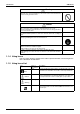
Instruction SiBE12-519 Outdoor Unit 17 22 19 20 18 21 Indoor Unit 1. Air filter 2. Titanium Apatite Photocatalytic Air-Purifying Filter: • These filters are attached to the inside of the air filters. 12. Indoor Unit ON/OFF switch: • Push this switch once to start operation. Push once again to stop it. • The operation mode refers to the following table. Temperature Air flow setting rate 22°C F(C)TKS COOL AUTO F(C)TXS AUTO AUTO 25°C 3. Air inlet Mode 4. Front panel 5. Panel tab 6.
Instruction SiBE12-519 Remote Controller 1 2 5 ECONO ON/OFF 3 POWERFUL TEMP 6 4 7 8 13 MODE FAN SWING SILENT COMFORT SENSOR ON CANCEL 9 10 12 11 16 OFF TIMER 18 17 15 14 1. Signal transmitter: • It sends signals to the indoor unit. 2. Display: • It displays the current settings. (In this illustration, each section is shown with all its displays ON for the purpose of explanation.) 3. ECONO button: ECONO operation 4. POWERFUL button: POWERFUL operation 5.
Instruction SiBE12-519 FTK(X)S20/25/35C Names of parts ■ Indoor Unit 1 2 3 4 5 6 11 10 9 7 8 12 13 14 15 16 ON OFF System Configuration 77
Instruction SiBE12-519 ■ Outdoor Unit 17 22 19 20 21 18 ■ ■ Indoor Unit 1. Air filter 2. Air purifying filter with photocatalytic deodorizing function: • These filters are attached to the inside of the air filters. 12. Indoor Unit ON/OFF switch: • Push this switch once to start operation. Push once again to stop it. • The operation mode refers to the following table. 3. Air inlet 4. Front grille FTKS FTXS 5. Grille tab 6. Room temperature sensor: • It senses the air temperature around the unit.
Instruction SiBE12-519 ■ Remote Controller 1 ON 2 C 5 HOME LEAVE ON/OFF 3 POWERFUL TEMP 6 4 7 MODE SILENT FAN SWING SENSOR 8 12 9 10 11 ON CANCEL 15 16 OFF TIMER 14 13 < ARC433A1, A2 > 1. Signal transmitter: • It sends signals to the indoor unit. 2. Display: • It displays the current settings. (In this illustration, each section is shown with all its displays ON for the purpose of explanation.) 3. HOME LEAVE button: for HOME LEAVE operation 4.
Instruction SiBE12-519 FDK(X)S25/35C Names of parts Indoor Unit 1 5 2 4 3 6 8 7 9 10 80 System Configuration
Instruction SiBE12-519 ■ Outdoor Unit 11 12 13 15 14 ■ Indoor Unit 1. Air outlet 2. Air outlet grille (Field supply) • Appearance of the Air outlet grille and Air inlet grille may differ with some models. 3. Display, Control panel 4. Suction grille (Option) • Appearance of the suction grille and Air inlet grille may differ with some models. 10. Indoor Unit ON/OFF switch • Push this switch once to start operation. Push once again to stop it.
Instruction SiBE12-519 ■ Remote Controller 1 ON 2 C 5 HOME LEAVE ON/OFF 3 POWERFUL TEMP 6 4 9 7 MODE SILENT FAN 8 10 ON CANCEL 13 14 OFF TIMER 12 11 < ARC433A7, A8 > 1. Signal transmitter: • It sends signals to the indoor unit. 2. Display: • It displays the current settings. (In this illustration, each section is shown with all its displays ON for the purpose of explanation.) 8. SILENT button: for OUTDOOR UNIT SILENT operation 9.
Instruction SiBE12-519 FLK(X)S25/35 Names of parts ■ Indoor Unit The indoor unit can be installed either to the ceiling or to a wall. The descriptions contained in this manual show the case when installation is being carried out to the ceiling. (The methods of operation used are the same when installing to a wall.
Instruction SiBE12-519 ■ Outdoor Unit 15 17 18 19 16 ■ Indoor Unit 1. Louvres (vertical blades): The louvres are inside of the air outlet. 2. Air outlet 3. Flap (horizontal blade) 13. Indoor unit ON/OFF switch • Push this switch once to start operation. Push once again to stop it. • The operation mode refers to the following table. 4. Grille tab 5. Air inlet FLKS FLXS 6. Display 7. Air filter 8.
Instruction SiBE12-519 ■ Remote Controller 1 ON 2 C 5 HOME LEAVE ON/OFF 3 POWERFUL TEMP 6 4 7 MODE SILENT FAN SWING 9 10 CANCEL 14 8 11 ON 15 OFF TIMER 13 12 < ARC433A5, A6 > 1. Signal Transmitter: • It sends signals to the indoor unit. 2. Display: • It displays the current settings. (In this illustration, each section is shown with all its displays ON for the purpose of explanation.) 3. HOME LEAVE button: for HOME LEAVE operation 4. POWERFUL button: for POWERFUL operation 5.
Instruction 2.4 SiBE12-519 Preparation before Operation Preparation Before Operation ■ To set the batteries 1. Press with a finger and slide the front cover to take it off. Position + and – correctly! 2 – + + 2. Set two dry batteries (AAA). – 3. Set the front cover as before. 3 1 ATTENTION ■ About batteries • When replacing the batteries, use batteries of the same type, and replace the two old batteries together. • When the system is not used for a long time, take the batteries out.
Instruction SiBE12-519 Preparation Before Operation ■ To operate the remote controller • To use the remote controller, aim the transmitter at the indoor unit. If there is anything to block signals between the unit and the remote controller, such as a curtain, the unit will not operate. • Do not drop the remote controller. Do not get it wet. • The maximum distance for communication is about 7 m. Receiver ■ To fix the remote controller holder on the wall 1.
Instruction SiBE12-519 To set the clock 1. Press “CLOCK button”. is displayed. C blinks. 2. Press “TIMER setting button” to set the clock to the present time. Holding down “ ” button rapidly ” or “ increases or decreases the time display. HOME LEAVE ON/OFF POWERFUL TEMP MODE SILENT FAN 3. Press “CLOCK button”. blinks. Turn the breaker ON Turning ON the breaker opens the flap, then closes it again. (This is a normal procedure.) ON SWING SENSOR 2 CANCEL 1.
Instruction SiBE12-519 2.5 AUTO · DRY · COOL · HEAT · FAN Operation AUTO · DRY · COOL · HEAT · FAN Operation The air conditioner operates with the operation mode of your choice. From the next time on, the air conditioner will operate with the same operation mode. ■ To start operation C 1. Press “MODE selector button” and select a operation mode. • Each pressing of the button advances the mode setting in sequence.
Instruction SiBE12-519 ■ To change the air flow rate setting 5. Press “FAN setting button”. DRY mode AUTO or COOL or HEAT or FAN mode Five levels of air flow rate setting from “ The air flow rate setting is not variable. plus “ ”“ ” to “ ” ” are available. • Indoor unit quiet operation When the air flow is set to “ ”, the noise from the indoor unit will become quieter. Use this when making the noise quieter. The unit might lose power when the fan strength is set to a weak level.
Instruction SiBE12-519 2.6 Adjusting the Air Flow Direction FTK(X)S20/25/35D Adjusting the Air Flow Direction You can adjust the air flow direction to increase your comfort. To adjust the horizontal blades (flaps) 1. Press “SWING button”. • “ ” is displayed on the LCD and the flaps will begin to swing. 2. When the flaps have reached the desired position, press “SWING button” once more. The display will go blank. The flaps will stop moving.
Instruction SiBE12-519 To start COMFORT AIRFLOW operation 3. Press “COMFORT AIRFLOW button”. The flap position will change, preventing air from blowing directly on the occupants of the room. • “ ” is displayed on the LCD. 〈COOL/DRY〉 The flap will go up. 〈HEAT〉 The flap will go down. To cancel COMFORT AIRFLOW operation 4. Press “COMFORT AIRFLOW button” again. • The flaps will return to the memory position from before COMFORT AIRFLOW mode.
Instruction SiBE12-519 FTK(X)S20/25/35C Adjusting the Air Flow Direction You can adjust the air flow direction to increase your comfort. ■ To adjust the horizontal blades (flaps) ON C 1. Press “SWING button”. The display will light up and the flaps will begin to swing. 2. When the flaps have reached the desired position, press “SWING button” once more. The display will go blank. The flaps will stop moving.
Instruction SiBE12-519 ■ To adjust the vertical blades (louvres) Hold the knob and move the louvres. (You will find a knob on the left-side and the right-side blades.) Notes on flaps and louvres angles • When “ SWING button ” is selected, the flaps swinging range depends on the operation mode. (See the figure.) ■ ATTENTION • Always use a remote controller to adjust the flaps angle. If you attempt to move it forcibly with hand when it is swinging, the mechanism may be broken.
Instruction SiBE12-519 FLK(X)S25/35 Adjusting the Air Flow Direction You can adjust the air flow direction to increase your comfort. ■ To adjust the horizontal blade (flap) ON C 1. Press “SWING button”. The display will light up and the flaps will begin to swing. 2. When the flaps have reached the desired position, press “SWING button” once more. The display will go blank. The flaps will stop moving.
Instruction SiBE12-519 ■ To adjust the vertical blades (louvres) • When adjusting the louvre, use a robust and stable stool and watch your steps carefully. Hold the knob and move the louvres. (You will find a knob on the left side and the right side blades.) Notes on flap and louvres angles • Unless [SWING] is selected, you should set the flap at a near- horizontal angle in COOL or DRY mode to obtain the best performance.
Instruction SiBE12-519 2.7 POWERFUL Operation POWERFUL Operation POWERFUL operation quickly maximizes the cooling (heating) effect in any operation mode. You can get the maximum capacity . To start POWERFUL operation 1. Press “POWERFUL button”. • POWERFUL operation ends in 20 minutes. Then the system automatically operates again with the settings which were used before POWERFUL operation. • When using POWERFUL operation, there are some functions which are not available. • “ ” is displayed on the LCD.
Instruction 2.8 SiBE12-519 OUTDOOR UNIT SILENT Operation OUTDOOR UNIT SILENT Operation OUTDOOR UNIT SILENT operation lowers the noise level of the outdoor unit by changing the frequency and fan speed on the outdoor unit. This function is convenient during night. ■ To start OUTDOOR UNIT SILENT operation C 1. Press “SILENT button”. ■ To cancel OUTDOOR UNIT SILENT operation HOME LEAVE ON/OFF POWERFUL TEMP MODE SILENT FAN 2. Press “SILENT button” again.
Instruction SiBE12-519 2.9 ECONO Operation ECONO Operation ECONO operation is a function which enables efficient operation by lowering the maximum power consumption value. To start ECONO operation 1. Press “ECONO button” . •“ ” is displayed on the LCD. To cancel ECONO operation 2. Press “ECONO button” again. •“ ” disappears from the LCD.
Instruction SiBE12-519 2.10 HOME LEAVE Operation HOME LEAVE Operation HOME LEAVE operation is a function which allows you to record your preferred temperature and air flow rate settings. ■ To start HOME LEAVE operation 1. Press “HOME LEAVE button” . • The HOME LEAVE lamp lights up. C ON OFF ■ To cancel HOME LEAVE operation 1, 2 HOME LEAVE ON/OFF POWERFUL TEMP MODE SILENT FAN 2. Press “HOME LEAVE button” again. • The HOME LEAVE lamp goes off.
Instruction SiBE12-519 What’s the HOME LEAVE operation Is there a set temperature and air flow rate which is most comfortable, a set temperature and air flow rate which you use the most? HOME LEAVE operation is a function that allows you to record your favorite set temperature and air flow rate. You can start your favorite operation mode simply by pressing the HOME LEAVE button on the remote controller. This function is convenient in the following situations. Useful in these cases. 1.
Instruction SiBE12-519 2.11 INTELLIGENT EYE Operation FTK(X)S20/25/35D INTELLIGENT EYE Operation “INTELLIGENT EYE” is the infrared sensor which detects the human movement. ■ To start INTELLIGENT EYE operation 1. Press “SENSOR button”. • “ ” is displayed on the LCD. ■ To cancel the INTELLIGENT EYE operation 2. Press “SENSOR button” again. • “ ” disappears from the LCD. [EX.
Instruction SiBE12-519 INTELLIGENT EYE Operation “INTELLIGENT EYE” is useful for Energy Saving Energy saving operation • Change the temperature –2°C in heating / +2°C in cooling / +2°C in dry mode from set temperature. • Decrease the air flow rate slightly in fan operation. (In FAN mode only) Notes on “INTELLIGENT EYE” • Application range is as follows. Vertical angle 90˚ (Side View) Horizontal angle 110˚ (Top View) 90˚ 7m 55˚ 55˚ 7m • Sensor may not detect moving objects further than 7m away.
Instruction SiBE12-519 FTK(X)S20/25/35C INTELLIGENT EYE Operation “INTELLIGENT EYE” is the infrared sensor which detects the human movement. ■ To start INTELLIGENT EYE operation C 1. Press “SENSOR button”. ■ To cancel the INTELLIGENT EYE operation HOME LEAVE ON/OFF POWERFUL TEMP MODE SILENT FAN 2. Press “SENSOR button” again. [EX.] SWING SENSOR 1, 2 When somebody in the room • Normal operation ON CANCEL OFF TIMER When nobody in the room • 20 min. after, start energy saving operation.
Instruction SiBE12-519 ■ To adjust the angle of the INTELLIGENT EYE sensor • You can adjust the angle of the INTELLIGENT EYE sensor to increase the detection area. (Adjustable angle: 15° to right and left of centre) 15˚ 15˚ • Gently push and slide the sensor to adjust the angle. • After adjusting the angle, wipe the sensor gently with a clean cloth, being careful not to scratch the sensor.
Instruction SiBE12-519 2.12 TIMER Operation TIMER Operation Timer functions are useful for automatically switching the air conditioner on or off at night or in the morning. You can also use OFF TIMER and ON TIMER in combination. ■ To use OFF TIMER operation C • Check that the clock is correct. If not, set the clock to the present time. 1. Press “OFF TIMER button”. is displayed. HOME LEAVE ON/OFF POWERFUL TEMP MODE SILENT FAN blinks. 2.
Instruction SiBE12-519 ■ To use ON TIMER operation • Check that the clock is correct. If not, set the clock to the present time. 1. Press “ON TIMER button”. is displayed. C blinks. 2. Press “TIMER Setting button” until the time setting reaches the point you like. • Every pressing of either button increases or decreases the time setting by 10 minutes. Holding down either button changes the setting rapidly. 3. Press “ON TIMER button” again.
Instruction SiBE12-519 2.13 Note for Multi System Note for Multi System 〈〈 What is a “Multi System”? 〉〉 This system has one outdoor unit connected to multiple indoor units. ■ Selecting the Operation Mode A room Outdoor unit 1. With the Priority Room Setting present but inactive or not present B room Living room C room When more than one indoor unit is operating, priority is given to the first unit that was turned on.
Instruction SiBE12-519 ■ Priority Room Setting The Priority Room Setting requires initial programming during installation. Please consult your retailer or dealer for assistance. The room designated as the Priority Room takes priority in the following situations; 1. Operation Mode Priority As the operation mode of the Priority Room takes precedence, the user can select a different operation mode from other rooms. 〈Example〉 * Room A is the Priority Room in the examples.
Instruction SiBE12-519 2.14 Care and Cleaning FTK(X)S20/25/35D Care and Cleaning CAUTION Before cleaning, be sure to stop the operation and turn the breaker OFF. Units Indoor unit, Outdoor unit and Remote controller 1. Wipe them with dry soft cloth. Front panel 1. Open the front panel. • Hold the panel by the tabs on the two sides and lift it unitl it stops with a click. 2. Remove the front panel. • Lift the front panel up, slide it slightly to the right, and remove it from the horizontal axle.
Instruction SiBE12-519 Filters 1. Open the front panel. 2. Pull out the air filters. • Push a little upwards the tab at the center of each air filter, then pull it down. 3. Take off the Titanium Apatite Photocatalytic Air-Purifying Filter. • Hold the recessed parts of the frame and unhook the four claws. Titanium Apatite Photocatalytic Air-Purifying Filter 4. Clean or replace each filter. See below. Air filter Filter frame Tab 5.
Instruction SiBE12-519 NOTE • Operation with dirty filters: (1) cannot deodorize the air. (2) cannot clean the air. (3) results in poor heating or cooling. (4) may cause odour. • To order Titanium Apatite Photocatalytic Air-Purifying Filter contact to the service shop there you bought the air conditioner. • Dispose of old filters as burnable waste. Item Titanium Apatite Photocatalytic Air-Purifying Filter. (without frame) 1 set Part No.
Instruction SiBE12-519 FTK(X)S20/25/35C Care and Cleaning CAUTION Before cleaning, be sure to stop the operation and turn the breaker OFF. Units ■ Indoor unit, Outdoor unit and Remote controller 1. Wipe them with dry soft cloth. ■ Front grille 1. Open the front grille. • Hold the grille by the tabs on the two sides and lift it unitl it stops with a click. 2. Remove the front grille. • Supporting the front grille with one hand, release the lock by sliding down the knob with the other hand.
Instruction SiBE12-519 Filters 1. Open the front grille. 2. Pull out the air filters. • Push a little upwards the tab at the center of each air filter, then pull it down. 3. Take off the air purifying filter with photocatalytic deodorizing function. Air purifying filter with photocatalytic deodorizing function Air filter • Hold the recessed parts of the frame and unhook the four claws. 4. Clean or replace each filter. See below. 5.
Instruction SiBE12-519 Check Check that the base, stand and other fittings of the outdoor unit are not decayed or corroded. Check that nothing blocks the air inlets and the outlets of the indoor unit and the outdoor unit. Check that the drain comes smoothly out of the drain hose during COOL or DRY operation. • If no drain water is seen, water may be leaking from the indoor unit. Stop operation and consult the service shop if this is the case. ■ Before a long idle period 1.
Instruction SiBE12-519 FDK(X)S25/35C CARE Care and Cleaning CAUTION • Only a qualified service person is allowed to perform maintenance. • Before cleaning, be sure to stop the operation and turn the breaker OFF. ■ Cleaning the air filter. 1.Removing the air filter. • Rear suction Pull the bottom side of the air filter backwards, over the 3 bends. • Bottom suction Pull the filter over the 3 bends situated at the backside of the unit. 2.Cleaning the air filter.
Instruction SiBE12-519 ■ Cleaning the drain pan • Clean the drain pan periodically, or drain piping may be clogged with dust and may result in water leakage. Ask your DAIKIN dealer to clean them. • Prepare a cover locally to prevent any dust in the air around the indoor unit from getting in the drain pan, if there is a great deal of dust present. CAUTION • Do not operate the air conditioner without filters, this to avoid dust accummulation inside the unit.
Instruction SiBE12-519 FLK(X)S25/35 Care and Cleaning CAUTION Before cleaning, be sure to stop the operation and turn the breaker OFF. Units ■ Indoor unit, Outdoor unit and Remote controller 1. Wipe them with dry soft cloth. ■ Front grille 1. Open the front grille. • Hold the grille by the tabs on the two sides and lift it unitl it stops. ON OFF 2. Clean the front grille • Wipe it with a soft cloth soaked in water. • Only neutral detergent may be used.
Instruction SiBE12-519 Filters 1. Open the front grille. 2. Pull out the air filters. • Push upwards the tab at the center of each air filter, then pull it down. ON OFF 3. Take off the air purifying filter, photocatalytic deodorizing filter. • Hold the recessed parts of the frame and unhook the four claws. ON OFF 4. Clean or replace each filter. See below. Air purifying filter or Photocatalytic deodorizing filter 5.
Instruction SiBE12-519 Check Check that the base, stand and other fittings of the outdoor unit are not decayed or corroded. Check that nothing blocks the air inlets and the outlets of the indoor unit and the outdoor unit. Check that the earth wire is not disconnected or broken. Check that the drain comes smoothly out of the drain hose during COOL or DRY operation. • If no drain water is seen, water may be leaking from the indoor unit. Stop operation and consult the service shop if this is the case.
Instruction SiBE12-519 2.15 Troubleshooting Trouble Shooting These cases are not troubles. The following cases are not air conditioner troubles but have some reasons. You may just continue using it. Case Explanation Operation does not start soon. • When ON/OFF button was pressed soon after operation was stopped. • When the mode was reselected. • This is to protect the air conditioner. You should wait for about 3 minutes. Hot air does not flow out soon after the start of heating operation.
Instruction SiBE12-519 Check again. Please check again before calling a repair person. Case The air conditioner does not operate. (OPERATION lamp is off) Check • Hasn’t a breaker turned OFF or a fuse blown? • Isn’t it a power failure? • Are batteries set in the remote controller? • Is the timer setting correct? Cooling (Heating) effect is poor.
Instruction SiBE12-519 Call the service shop immediately. WARNING ■When an abnormality (such as a burning smell) occurs, stop operation and turn the breaker OFF. Continued operation in an abnormal condition may result in troubles, electric shocks or fire. Consult the service shop where you bought the air conditioner. ■Do not attempt to repair or modify the air conditioner by yourself. Incorrect work may result in electric shocks or fire. Consult the service shop where you bought the air conditioner.
Instruction SiBE12-519 Fault diagnosis FAULT DIAGNOSIS BY REMOTE CONTROLLER In the ARC433A series, the temperature display sections on the main unit indicate corresponding codes. 1. When the TIMER CANCEL button is held down for 5 seconds, a “ ” indication flashes on the temperature display section. ON C HOME LEAVE ON/OFF POWERFUL TEMP MODE SILENT FAN ON SWING SENSOR CANCEL TIMER CANCEL button It cancels the timer setting. OFF TIMER 2.
Instruction SiBE12-519 LED ON OUTDOOR UNIT PCB 3MXS, 3MKS, 4MXS, 4MKS series GREEN RED MICROCOMPUTER NORMAL MALFUNCTION DETECTION LED-A LED1 LED2 LED3 LED4 DIAGNOSIS NORMAL CHECK INDOOR UNIT HIGH PRESSURE PROTECTOR WORKED OR FREEZE-UP IN OPERATING UNIT OR STAND-BY UNIT ∗ OVERLOAD RELAY WORKED OR HIGH DISCHARGE PIPE TEMPERATURE FAULTY COMPRESSOR START INPUT OVERCURRENT ∗ THERMISTOR OR CT ABNORMALITY HIGH TEMPERATURE SWITCHBOX HIGH TEMPERATURE AT INVERTER CIRCUIT HEATSINK ∗ OUTPUT OVERCURRENT ∗
Instruction 126 SiBE12-519 System Configuration
SiBE12-519 Part 6 Service Diagnosis 1. 2. 3. 4. Caution for Diagnosis..........................................................................128 Problem Symptoms and Measures .....................................................130 Service Check Function ......................................................................131 Troubleshooting ..................................................................................134 4.1 4.2 4.3 4.4 4.5 4.6 4.7 4.8 4.9 4.10 4.11 4.12 4.13 4.14 4.15 4.16 4.
Caution for Diagnosis SiBE12-519 1. Caution for Diagnosis The operation lamp flashes when any of the following errors is detected. 1. When a protection device of the indoor or outdoor unit is activated or when the thermistor malfunctions, disabling equipment operation. 2. When a signal transmission error occurs between the indoor and outdoor units. In either case, conduct the diagnostic procedure described in the following pages.
SiBE12-519 Caution: Caution for Diagnosis Operation stops suddenly. (Operation lamp blinks.) Cause of above trouble could be "Operation mode conflict". Check followings; Are the operation modes all the same for indoor units connected to Multi system outdoor unit? If not set all indoor units to the same operation mode and confirm that the operation lamp is not blinking.
Problem Symptoms and Measures SiBE12-519 2. Problem Symptoms and Measures Symptom Check Item None of the Units Operates. Check the power supply. Details of Measure Check to make sure that the rated voltage is supplied. Check the type of the indoor units. Check to make sure that the indoor unit type is compatible with the outdoor unit. Check the outdoor air temperature.
SiBE12-519 Service Check Function 3. Service Check Function In the ARC433A series remote controller, the temperature display sections on the main unit indicate corresponding codes. Check Method 1 1. When the timer cancel button is held down for 5 seconds, a “00” indication flashes on the temperature display section. ECONO POWERFUL ON/OFF TEMP MODE FAN SWING SILENT COMFORT SENSOR ON CANCEL TIMER CANCEL button It cancels the timer setting. OFF TIMER (R4271) 2.
Service Check Function Check Method 2 SiBE12-519 1. Enter the diagnosis mode. Press the 3 buttons (TEMP ,TEMP , MODE) simultaneously. (R4272) The digit of the number of tens blinks. Try again from the start when the digit does not blink. (R4273) 2. Press the TEMP button. Press TEMP or TEMP and change the digit until you hear the sound of “beep” or “pi pi”. (R4274) 3. Diagnose by the sound. “ pi ” : The number of tens does not accord with the error code.
SiBE12-519 Service Check Function 5. Press the TEMP button. Press TEMP or TEMP and change the digit until you hear the sound of “beep”. (R4277) 6. Diagnose by the sound. “ pi ” : The both numbers of tens and units do not accord with the error code. “ pi pi ” : The number of tens accords with the error code. “ beep ” : The both numbers of tens and units accord with the error code. 7. Determine the error code. The digits indicated when you hear the “beep” sound are error code.
Troubleshooting SiBE12-519 4. Troubleshooting 4.
SiBE12-519 4.2 Troubleshooting Indoor Unit PCB Abnormality A1 Remote Controller Display Method of Malfunction Detection Evaluation of zero-cross detection of power supply by indoor unit. Malfunction Decision Conditions When there is no zero-cross detection in approximately 10 continuous seconds. Supposed Causes Faulty indoor unit PCB Faulty connector connection Troubleshooting Caution Be sure to turn off power switch before connect or disconnect connector, or parts damage may be occurred.
Troubleshooting 4.3 SiBE12-519 Freeze-up Protection Control or High Pressure Control Remote Controller Display A5 Method of Malfunction Detection High pressure control (heat pump model only) Malfunction Decision Conditions High pressure control Supposed Causes 136 During heating operations, the temperature detected by the indoor heat exchanger thermistor is used for the high pressure control (stop, outdoor fan stop, etc.
SiBE12-519 Troubleshooting Troubleshooting Caution Check No.06 Refer to P.173 Be sure to turn off power switch before connect or disconnect connector, or parts damage may be occurred. Check the air passage. Is there any short-circuit? YES Provide sufficient air passage. NO Check the intake air filter. Is it very dirty? YES Clean the air filter. NO Check the dust accumulation on the indoor unit heat exchanger. Is it very dirty? YES Clean the heat exchanger. NO Check No.
Troubleshooting 4.4 SiBE12-519 Fan Motor or Related Abnormality 4.4.1 AC Motor Remote Controller Display A6 Method of Malfunction Detection The rotation speed detected by the Hall IC during fan motor operation is used to determine abnormal fan motor operation. Malfunction Decision Conditions When the detected rotation speed is less than 50% of the HH tap under maximum fan motor rotation demand. Supposed Causes Operation halt due to short circuit inside the fan motor winding.
SiBE12-519 Troubleshooting 4.4.2 DC Motor Remote Controller Display A6 Method of Malfunction Detection The rotation speed detected by the Hall IC during fan motor operation is used to determine abnormal fan motor operation. Malfunction Decision Conditions When the detected rotation speed is less than 50% of the H tap under maximum fan motor rotation demand. Supposed Causes Service Diagnosis Operation halt due to short circuit inside the fan motor winding.
Troubleshooting SiBE12-519 Troubleshooting Caution Check No.01 Refer to P.170 Be sure to turn off power switch before connect or disconnect connector, or parts damage may be occurred. Turn off power supply and rotate fan by hand. Does fan rotate smoothly? NO Replace fan motor. YES Turn power ON and operate fan. Does it rotate? Turn off power supply NO and disconnect fan motor connector, then turn power ON. YES Check No.
SiBE12-519 4.5 Troubleshooting Thermistor or Related Abnormality (Indoor Unit) C4, C9 Remote Controller Display Method of Malfunction Detection The temperatures detected by the thermistors are used to determine thermistor errors. Malfunction Decision Conditions When the thermistor input is more than 4.96 V or less than 0.04 V during compressor operation∗. ∗ (reference) When above about 212°C (less than 120 ohms) or below about –50°C (more than 1,860 kohms).
Troubleshooting 4.6 SiBE12-519 Freeze-up Protection Control Remote Controller Display A5 Method of Malfunction Detection Indoor unit icing, during cooling operation, is detected by checking the temperatures sensed by the indoor unit heat exchanger thermistor and room temperature thermistor that are located in a shut-down room. At another room (the indoor unit is normal), “UH” is displayed on the remote controller.
SiBE12-519 Troubleshooting Troubleshooting Check No.04 Refer to P.171 Check No.06 Refer to P.173 Caution Be sure to turn off power switch before connect or disconnect connector, or parts damage may be occurred. Check the wiring and piping. Wiring or piping out of spec? YES Correct the wiring or piping error. NO Check No. 04 Check the electronic expansion valve. Normal? NO Replace the defective EV or coil. YES Check No. 06 Check the outdoor unit heat exchanger thermistor.
Troubleshooting 4.7 SiBE12-519 OL Activation (Compressor Overload) Remote Controller Display E5 Method of Malfunction Detection A compressor overload is detected through compressor OL. Malfunction Decision Conditions If the compressor OL is activated twice, the system will be shut down. The error counter will reset itself if this or any other error does not occur during the following Supposed Causes 60-minute compressor running time (total time).
SiBE12-519 4.8 Troubleshooting Compressor Lock E6 Remote Controller Display Method of Malfunction Detection A compressor lock is detected by checking the compressor running condition through the position detection circuit. Malfunction Decision Conditions The position detection circuit detects a compressor frequency of below 5 Hz for several tens Supposed Causes Compressor locked of seconds. The system will be shut down if the error occurs 16 times.
Troubleshooting 4.9 SiBE12-519 DC Fan Lock Remote Controller Display E7 Method of Malfunction Detection A fan motor or related error is detected by checking the high-voltage fan motor rpm being detected by the Hall IC. Malfunction Decision Conditions The fan does not start in 30 seconds even when the fan motor is running. The system will be shut down if the error occurs 16 times.
SiBE12-519 Troubleshooting 4.10 Input Over Current Detection Remote Controller Display E8 Method of Malfunction Detection An input over-current is detected by checking the input current value being detected by CT with the compressor running. Malfunction Decision Conditions The following CT input with the compressor running continues for 2.5 seconds. Supposed Causes Service Diagnosis CT input: Above 11 A The system will be shut down if the error occurs 16 times.
Troubleshooting SiBE12-519 Troubleshooting Caution Check No.07 Refer to P.174 Check No.08 Refer to P.175 Be sure to turn off power switch before connect or disconnect connector, or parts damage may be occurred. ∗ An input over-current may result from wrong internal wiring. If the wires have been disconnected and reconnected for part replacement, for example, and the system is interrupted by an input over-current, take the following procedure. Get restarted and measure the input current.
SiBE12-519 Troubleshooting 4.11 Four Way Valve Abnormality Remote Controller Display EA Method of Malfunction Detection The liquid pipe temperature thermistor, the outdoor air temperature thermistor and the outdoor unit heat exchanger thermistor are checked to see if they function within their normal ranges in the operating mode. Malfunction Decision Conditions Cooling / dry operation Supposed Causes Service Diagnosis A following condition occurs after 3 minutes of the compressor start.
Troubleshooting SiBE12-519 Troubleshooting Caution Check No.05 Refer to P.172 Check No.06 Refer to P.173 Be sure to turn off power switch before connect or disconnect connector, or parts damage may be occurred. Four way valve coil disconnected (loose)? YES NO YES Harness out of connector? Check No.11 Refer to P.176 Correct. Reconnect. NO Check the continuity of the four way valve coil and harness. Disconnect the harness from the connector. Resistance between harnesses about 3kΩ±0.
SiBE12-519 Troubleshooting 4.12 Discharge Pipe Temperature Control Remote Controller Display F3 Method of Malfunction Detection The discharge pipe temperature control (stop, frequency drooping, etc.) is checked with the temperature being detected by the discharge pipe thermistor. Malfunction Decision Conditions If the temperature being detected by the discharge pipe thermistor rises, the compressor will stop. The temperature at which the compressor halts varies according to the frequency.
Troubleshooting SiBE12-519 4.13 High Pressure Control in Cooling Remote Controller Display F6 Method of Malfunction Detection High-pressure control (stop, frequency drop, etc.) is activated in the cooling mode if the temperature being sensed by the heat exchanger thermistor exceeds the limit. Malfunction Decision Conditions Activated when the temperature being sensed by the heat exchanger thermistor rises above Supposed Causes 152 54°C.
SiBE12-519 Troubleshooting Troubleshooting Caution Check No.04 Refer to P.171 Check No.06 Refer to P.173 Be sure to turn off power switch before connect or disconnect connector, or parts damage may be occurred. Check the installation space. Check No.07 Installation condition check Abnormal Normal Check No.07 Refer to P.174 Check No.09 Outdoor fan check Abnormal Normal Check No.09 Refer to P.175 Change the air outlet grille position. Change the installation location. Clean the heat exchanger.
Troubleshooting SiBE12-519 4.14 Position Sensor Abnormality Remote Controller Display H6 Method of Malfunction Detection A compressor startup failure is detected by checking the compressor running condition through the position detection circuit. Malfunction Decision Conditions The compressor is not running in about 15 seconds after the compressor run command Supposed Causes signal is sent.
SiBE12-519 Troubleshooting 4.15 CT or Related Abnormality Remote Controller Display H8 Method of Malfunction Detection A CT or related error is detected by checking the compressor running frequency and CTdetected input current. Malfunction Decision Conditions The compressor running frequency is above 68 Hz and the CT input is below 0.1 V. (The input current is also below 1.25 A.) If this error repeats 4 times, the system will be shut down.
Troubleshooting SiBE12-519 Troubleshooting Caution Check No.12 Refer to P.176 Be sure to turn off power switch before connect or disconnect connector, or parts damage may be occurred. Turn off the power and turn it on again. Get the system started. ∗ Running current as shown at right with relay cable 1 or 2? YES Current (guideline) NO Check No. 12 Check the capacitor voltage. Rising with increasing frequency 2 sec DC290~380V? Replace the outdoor unit PCB.
SiBE12-519 Troubleshooting 4.16 Thermistor or Related Abnormality (Outdoor Unit) Remote Controller Display P4,J3,J6,J8,J9,H9 Method of Malfunction Detection This type of error is detected by checking the thermistor input voltage to the microcomputer. [A thermistor error is detected by checking the temperature.] Malfunction Decision Conditions The thermistor input is above 4.96 V or below 0.04 V with the power on.
Troubleshooting SiBE12-519 Troubleshooting Caution Check No.06 Refer to P.173 Be sure to turn off power switch before connect or disconnect connector, or parts damage may be occurred. Turn on the power again. Error displayed again on remote controller? NO Reconnect. YES Connector or thermistor disconnected? YES Reconnect. NO Check No. 06 Check the thermistor resistance value. NO Normal? YES Check No. 06 Check the indoor unit heat exchanger thermistor resistance value in the heating mode.
SiBE12-519 Troubleshooting 4.17 Electrical Box Temperature Rise Remote Controller Display L3 Method of Malfunction Detection An electrical box temperature rise is detected by checking the radiation fin thermistor with the compressor off. Malfunction Decision Conditions With the compressor off, the radiation fin temperature is above 80°C. The error is cleared when the temperature drops below 70°C.
Troubleshooting SiBE12-519 Troubleshooting Caution Check No.06 Refer to P.173 Be sure to turn off power switch before connect or disconnect connector, or parts damage may be occurred. Turn off the power and turn it on again. Check No.07 Refer to P.174 Error again or outdoor unit fan activated? Check No.09 Refer to P.175 WARNING To cool down the electricals, the outdoor unit fan gets started when the radiation fin temperature rises above 80˚C and stops itself when it drops below 70˚C.
SiBE12-519 Troubleshooting 4.18 Radiation Fin Temperature Rise Remote Controller Display L4 Method of Malfunction Detection A radiation fin temperature rise is detected by checking the radiation fin thermistor with the compressor on. Malfunction Decision Conditions If the radiation fin temperature with the compressor on is above 90°C, If a radiation fin temperature rise takes place 4 times successively, the system will be shut Supposed Causes Service Diagnosis down.
Troubleshooting SiBE12-519 Troubleshooting Caution Check No.06 Refer to P.173 Be sure to turn off power switch before connect or disconnect connector, or parts damage may be occurred. Turn off the power and turn it on again to get the system started. Check No.07 Refer to P.174 Error displayed again? Check No.09 Refer to P.175 YES NO Check No. 06 Check the thermistor resistance value. z Fin thermistor Check the radiation fin temperature.
SiBE12-519 Troubleshooting 4.19 Output Over Current Detection Remote Controller Display L5 Method of Malfunction Detection An output over-current is detected by checking the current that flows in the inverter DC section. Malfunction Decision Conditions A position signal error occurs while the compressor is running. A speed error occurs while the compressor is running. An output over-current input is fed from the output over-current detection circuit to the microcomputer.
Troubleshooting SiBE12-519 Troubleshooting Caution Check No.07 Refer to P.174 Be sure to turn off power switch before connect or disconnect connector, or parts damage may be occurred. ∗ An output over-current may result from wrong internal wiring. If the wires have been disconnected and reconnected for part replacement, for example, and the system is interrupted by an output over-current, take the following procedure. NO Stop valve fully open? Check No.08 Refer to P.175 Check No.13 Refer to P.
SiBE12-519 Troubleshooting 4.20 Insufficient Gas Remote Controller Display Method of Malfunction Detection U0 Gas shortage detection I : A gas shortage is detected by checking the power consumption value and the compressor running frequency. Gas shortage detection II : A gas shortage is detected by checking the difference between indoor unit heat exchanger temperature and room temperature as well as the difference between outdoor unit heat exchanger temperature and room temperature.
Troubleshooting SiBE12-519 Troubleshooting Caution Check No.04 Refer to P.171 Check No.06 Refer to P.173 Be sure to turn off power switch before connect or disconnect connector, or parts damage may be occurred. Any thermistor disconnected? NO YES Reconnect in position. * Discharge pipe thermistor * Indoor / outdoor unit heat exchanger thermistor * Room temperature thermistor * Outdoor air thermistor YES Open the stop valve. Stop valve closed? NO Check for gas leakage.
SiBE12-519 Troubleshooting 4.21 Over-voltage Detection U2 Remote Controller Display Method of Malfunction Detection An abnormal voltage rise is detected by checking the detection circuit or DC voltage detection circuit.
Troubleshooting SiBE12-519 4.22 Anti-icing Function in Other Rooms / Unspecified Voltage (between Indoor and Outdoor Units) Remote Controller Display UA,UH Method of Malfunction Detection A wrong connection is detected by checking the combination of indoor and outdoor units on the microcomputer.
SiBE12-519 Troubleshooting 4.23 Outdoor Unit PCB Abnormality or Signal Transmission Circuit Abnormality Remote Controller Display U4 Method of Malfunction Detection The data received from the outdoor unit in indoor unit-outdoor unit signal transmission is checked whether it is normal. Malfunction Decision Conditions When the data sent from the outdoor unit cannot be received normally, or when the content of the data is abnormal.
Check SiBE12-519 5. Check 5.1 How to Check 5.1.1 Fan Motor Connector Output Check Check No.01 1. 2. 3. 4. 5. Check connector connection. Check motor power supply voltage output (pins 4-7). Check motor control voltage (pins 4-3). Check rotation command voltage output (pins 4-2). Check rotation pulse input (pins 4-1). S1 7 6 5 4 3 2 1 Motor power supply voltage Unused Unused P.
SiBE12-519 Check 5.1.2 Electronic Expansion Valve Check Check No.04 Conduct the followings to check the electronic expansion valve (EV). 1. Check to see if the EV connector is correctly inserted in the PCB. Compare the EV unit and the connector number. 2. Turn the power off and back on again, and check to see if all the EVs generate latching sound. 3. If any of the EVs does not generate latching noise in the above step 2, disconnect that connector and check the continuity using a tester.
Check SiBE12-519 5.1.3 Four Way Valve Performance Check Check No.05 Turn off the power and turn it on again. Start the heating-mode run. S80 voltage at DC 180-220 V with compressor on? (Fig. 1) ∗ Four way valve coil Cooling / dry : No continuity Heating : Continuity NO Replace the outdoor unit PCB. YES Disconnect the four way valve coil from the connector and check the continuity. Four way valve coil resistance at 3kΩ±0.5kΩ? NO YES Replace the four way valve coil. Replace the four way valve.
SiBE12-519 Check 5.1.4 Thermistor Resistance Check Check No.06 Remove the connectors of the thermistors on the PCB, and measure the resistance of each thermistor using tester. The relationship between normal temperature and resistance is shown in the graph and the table below. Thermistor R25°C=20kΩ B=3950 Temperature (°C) -20 -15 -10 -5 0 5 10 15 20 25 30 35 40 45 50 Service Diagnosis 211.0 (kΩ) 150 116.5 88 67.2 51.9 40 31.8 25 20 16 13 10.6 8.7 7.
Check SiBE12-519 5.1.5 Installation Condition Check Check No.07 Installation condition check Check the allowable dimensions of the air suction and discharge area. Normal Does the discharged air from other outdoor unit cause an increase of the suction air temperature? Abnormal YES Change the position of the air discharge grille or the installation location. Change the position of the air discharge grille or the installation location.
SiBE12-519 Check 5.1.6 Discharge Pressure Check Check No.08 Discharge pressure check NO High Replace compessor. YES Is the stop valve open? NO Open the stop valve. YES Is the connection pipe deformed? NO Replace the pipe installed at the site. YES Are the heat exchanger and air filter dirty? Dirty Clean. Not dirty Replace the compressor. (R3049) 5.1.7 Outdoor Unit Fan System Check (With DC Motor) Check No.09 Check the outdoor unit fan system.
Check SiBE12-519 5.1.8 Inverter Units Refrigerant System Check Check No.11 Refrigerant system check Is the discharge thermister disconnected from the holder? YES Correct the problem. NO Is the temperature of the four way valve suction pipe abnormaly high? YES Four way valve defective. Replace the four way valve. NO YES Is any moisture found in sight glass? Conduct the check after operating the equipment for a sufficient length of time. Conduct vacuum drying. NO Check for gas leaks.
SiBE12-519 Check 5.1.10 Power Transistor Check Check No.13 Checking the power transistor z Never touch any live parts for at least 10 minutes after turning off the circuit breaker. z If unavoidably necessary to touch a live part, make sure the power transistor's supply voltage is below 50 V using the tester. z For the UVW, make measurements at the Faston terminal on the PCB or the relay connector.
Check SiBE12-519 5.1.12 Turning Speed Pulse Input on the Outdoor Unit PCB Check Check No.15 Make sure the voltage of 290~380V is being applied. (1) Stop the operation first and then the power off, and disconnect the connector S70. (2) Make sure there is about DC 280 V between pins 4 and 7. (3) With the system and the power still off, reconnect the connector S70. (4) Make a turn of the fan motor with a hand, and make sure the pulse (0-15 V) appears twice at pins 1 and 4.
SiBE12-519 Part 7 Removal Procedure 1. Outdoor Unit........................................................................................180 1.1 1.2 1.3 1.4 1.5 1.6 1.7 1.8 Removal Procedure Removal of the Panels / Fan Motor......................................................180 Removal of the PCB.............................................................................185 Removal of the Electrical Box ..............................................................190 Removal of the Sound Blanket..
Outdoor Unit SiBE12-519 1. Outdoor Unit 1.1 Removal of the Panels / Fan Motor Procedure Warning Be sure to wait 10 minutes or more after turning off all power supplies before disassembling work. Procedure Step Points 1. Features Take care not to cut your finger by the fins of the heat exchanger. 1 180 Loosen the two screws. Pull the stop valve cover down and remove it.
SiBE12-519 Outdoor Unit Procedure Step Points Make sure that the seven claws are fit securely when reassembling. 2. Remove the top panel. 1 Loosen the four screws and lift the top panel. 2 Loosen the seven screws of the front panel.
Outdoor Unit Procedure Step 3 SiBE12-519 Undo the claws and pull the front panel out towards you. Points The front panel has four claws. It is possible to remove the bell mouth. 3. Remove the propeller fan. 1 Release the fan motor lead wire from the ditch of the electrical box. 2 182 Disconnect the connector for fan motor (S70).
SiBE12-519 Outdoor Unit Procedure Step 3 Pull the fan motor lead wire away. 4 Release the four claws and remove the electrical box cover. 5 Unscrew the washerfitted nut (M10) of the propeller fan with a spanner.
Outdoor Unit Procedure Step 6 SiBE12-519 Remove the propeller fan. Points Align mark of the propeller fan with D-cut section of the motor shaft when reassembling. (R2885) 7 Remove the two screws from the fan motor. 8 Unlock the fixing claws and release the lead wire. Put the lead wire through the back of the motor when reassembling.
SiBE12-519 1.2 Outdoor Unit Removal of the PCB Procedure Warning Be sure to wait 10 minutes or more after turning off all power supplies before disassembling work. Procedure Step Disconnect the fan motor lead wire. 1. Remove the PCB. 1 The illustration shows appearance of the PCB. Points The PCB is upside down for the sake of quality improvement. Lead free soldering PbF is adopted. 2 The illustration shows arrangement of the relaying connectors. 3 Disconnect the connectors.
Outdoor Unit Procedure Step 4 Disconnect the relaying connector for the compressor. 5 Disconnect the two connectors of the reactor. 6 Disconnect the earth terminal. Disconnect the connection wiring and the power supply wiring.
SiBE12-519 Outdoor Unit Procedure Step Points 8 Disconnect the harnesses. 9 Loosen the screw of the terminal strip board. A thermal fuse is united with Loosen the four screws of the PCB. The PCB is upside down for 10 the terminal strip board. the sake of quality improvement. Service monitor (LED-A) You can see the LED through the slit.
Outdoor Unit Procedure Step 11 SiBE12-519 Lift the PCB from the heat exchanger side, and release from the two claws. Points Mind that not to break the PCB with excessive stress because it sticks fast to the radiator fin. Be sure to use silicon when reassembling. Silicon: parts no.1172698 12 Disconnect the connector for fin thermistor (S93). 13 Disconnect the two SH condenser lead wires.
SiBE12-519 Outdoor Unit Procedure Step 14 The illustration shows the layout of the PCB (parts side). 15 Loosen the two screws of the radiator fin. 16 Disconnect the reactor lead wires and remove the SH condenser. 17 Remove the screw of the electrical box.
Outdoor Unit 1.3 SiBE12-519 Removal of the Electrical Box Procedure Warning Be sure to wait 10 minutes or more after turning off all power supplies before disassembling work. Procedure Step Points Remove the top panel and the front panel. 1. Remove the electrical box. 1 Disconnect the connection wirings for each room. 2 Release the outdoor air thermistor from the holder. 3 Loosen the four screws and remove the electrical box cover.
SiBE12-519 Procedure Step 4 5 Outdoor Unit Points Disconnect all the connectors. As for the connectors, refer Disconnect the discharge pipe thermistor. True up the tips of the to the removal procedure of PCB. thermistor and the clip. Mind that not to lose the clip for the discharge pipe thermistor. 6 Loosen the screw of the electrical box.
Outdoor Unit Procedure Step 7 Lift the electrical box up. 8 Release the wire clamp from the back side of the electrical box. 9 Remove the electrical box.
SiBE12-519 1.4 Outdoor Unit Removal of the Sound Blanket Procedure Warning Be sure to wait 10 minutes or more after turning off all power supplies before disassembling work. Procedure Step 1 Loosen the five screws of the right side panel. 2 Release the clamp of the compressor lead wire from the partition plate.
Outdoor Unit Procedure Step 3 SiBE12-519 The partition plate is fixed to the bottom frame with a claw. Lift it and pull out towards you. Points Fit the claw of the partition plate to the bottom frame when reassembling. 4 Loosen two screws of the partition plate. 5 Untie the fixing string and remove the sound blanket (side-outer). Loosen the screw to remove Remove the sound blanket (top). Since the piping ports on the 6 194 the reactor from the partition plate.
SiBE12-519 Outdoor Unit Procedure Step 7 Remove the sound blanket (side-inner A). 8 Remove the sound blanket (side-inner B). 9 Remove the sound blanket (bottom).
Outdoor Unit 1.5 Removal of the Thermistor Procedure 1 Disconnect the discharge pipe thermistor. 2 Disconnect the gas and liquid pipe thermistor. 196 Warning Be sure to wait 10 minutes or more after turning off all power supplies before disassembling work. Procedure Step 3 SiBE12-519 Points Mind that not to lose the clips for thermistors. Disconnect the heat exchanger thermistor.
SiBE12-519 1.6 Outdoor Unit Removal of the Four Way Valve Procedure Warning Be sure to wait 10 minutes or more after turning off all power supplies before disassembling work. Procedure Step Points 1. Remove the peripheries. Remove the followings so as not to be burned by a gas brazing machine. Four way valve coil Electronic expansion valve coil Putty 1 Loosen the screw and remove the four way valve coil. 2 Remove the sheet of putty.
Outdoor Unit Step SiBE12-519 Procedure Points Warning Ventilate when refrigerant leaks during the work. (If refrigerant contacts fire, it will cause to arise toxic gas.) Caution Be careful about the four way valve, pipes and so on, which were heated up by a gas brazing machine, so as not to get burnt your hands. Cautions for restoration 1. Restore the piping by nonoxidation brazing. Braze it quickly when no nitrogen gas can be used. 2.
SiBE12-519 1.7 Removal of the Electronic Expansion Valve Procedure Warning Be sure to wait 10 minutes or more after turning off all power supplies before disassembling work. Procedure Step 1 Outdoor Unit Remove the electronic expansion valve coil. Points Fit the claw of the electronic expansion valve coil as it was when reassembling. Warning Ventilate when refrigerant leaks during the work. (If refrigerant contacts fire, it will cause to arise toxic gas.
Outdoor Unit 1.8 Removal of the Compressor Procedure Warning Be sure to wait 10 minutes or more after turning off all power supplies before disassembling work. Procedure Step 1 SiBE12-519 Points Remove the terminal cover. Be careful so as not to burn the compressor terminals or the name plate. Make a note. 2 200 Unscrew the nut of the compressor.
SiBE12-519 Outdoor Unit Procedure Step Points Before working, 3 make sure that the refrigerant is empty in the circuit. Be sure to apply nitrogen replacement when heating up the brazed part. Heat up the brazed part of the discharge side and disconnect. 4 Heat up the brazed part of the suction side and disconnect. 5 Lift the compressor up and remove it.
Outdoor Unit 202 SiBE12-519 Removal Procedure
SiBE12-519 Part 8 Others 1. Others .................................................................................................204 1.1 Test Run from the Remote Controller ..................................................204 1.2 Jumper Settings ...................................................................................
Others SiBE12-519 1. Others 1.1 Test Run from the Remote Controller For Heat pump In cooling mode, select the lowest programmable temperature; in heating mode, select the highest programmable temperature. Trial operation may be disabled in either mode depending on the room temperature. After trial operation is complete, set the temperature to a normal level.
SiBE12-519 1.2 Others Jumper Settings 1.2.1 When Two Units are Installed in One Room When two indoor units are installed in one room, the two wireless remote controllers can be set for different addresses. How to set the different addresses Control PCB of the indoor unit (1) Remove the electrical box. (2) Cut the address jumper JA on the control PCB. Wireless remote controller (1) Slide the front cover and take it off. (2) Cut the address jumper J4.
Others SiBE12-519 1.2.3 Adjusting the Angle of the Intelligent Eye Sensor FTK(X)S20-35C Once installation of the indoor unit is complete, adjust the angle of the Intelligent-eye sensor to ensure the detection area properly covers the room. (Adjustable angle : 15° to right and left of center) Gently push and slide the sensor to adjust the angle. Aim so that the sensor is pointing to the center of the room, or to the part of the room that is most frequently used.
SiBE12-519 Part 9 Appendix 1. Piping Diagrams..................................................................................208 1.1 Indoor Units ..........................................................................................208 1.2 Outdoor Units .......................................................................................210 2. Wiring Diagrams..................................................................................211 2.1 Indoor Units ......................................
Piping Diagrams SiBE12-519 1. Piping Diagrams 1.1 Indoor Units 1.1.1 Wall Mounted Type FTKS20D(2)VMW(L)(9), FTKS25D(2)VMW(L)(9) FTKS35D(2)VMW(L)(9), FTXS20D(2)VMW(L)(9) FTXS25D(2)VMW(L)(9), FTXS35D(2)VMW(L)(9) FTKS20CVMB(9), FTKS25CVMB(9)(8) FTKS35CVMB(9)(8) INDOOR UNIT INDOOR UNIT MAFFLER ASSY HEAT EXCHANGER 7.0CuT 7.0CuT 6.4CuT 7.9CuT THERMISTOR ON HEAT EXCH. 7.9CuT 6.4CuT FIELD PIPING HEAT EXCHANGER 6.4CuT THERMISTOR ON HEAT EXCH. 6.4CuT 6.4CuT 6.4CuT CROSS FLOW FAN (6.
SiBE12-519 Piping Diagrams 1.1.2 Duct Connected Type FDK(X)S25CVMB, FDK(X)S35CVMB INDOOR UNIT (6.4CuT) HEAT EXCHANGER FIELD PIPING (6.4CuT) CDXS25CVMB CDKS25CVMB CDXS35CVMB CDKS35CVMB CDXS25CVMA CDXS35CVMA FDXS25CVMB FDXS35CVMB FDKS25CVMB FDKS35CVMB CDXS50CVMB CDKS50CVMB CDXS60CVMB CDKS60CVMB CDXS50CVMA CDXS60CVMA THERMISTOR ON HEAT EXCH. SIROCCO FAN M FAN MOTOR FIELD PIPING ( CuT) ( CuT) 9.5 12.7 REFRIGERANT FLOW COOLING HEATING 4D045449B 1.1.
Piping Diagrams 1.2 SiBE12-519 Outdoor Units 2MKS40DVMB OUTDOOR UNIT OUTDOOR TEMPERATURE THERMISTOR (DOA) BRANCH PIPE 7.9CuT HEAT EXCHANGER 6.4CuT 7.9CuT MOTOR OPERATED VALVE EVA FILTER FILTER FILTER 6.4CuT BRANCH 7.9CuT PIPE MOTOR OPERATED VALVE EVB FILTER FILTER FILTER 6.4CuT 7.9CuT 6.4CuT LIQUID LINE STOP VALVE 6.4CuT 6.4CuT LIQUID LINE STOP VALVE 6.4CuT ROOM A (6.4 CuT) ROOM B (6.4 CuT) DISTRIBUTOR HEAT EXCHANGER THERMISTOR (DE) FEILD PIPING LIQUID 4.0CuT 4.0CuT M FAN MOTOR 7.
SiBE12-519 Wiring Diagrams 2. Wiring Diagrams 2.1 Indoor Units 2.1.1 Wall Mounted Type FTKS20D(2)VMW(L)(9), FTKS25D(2)VMW(L)(9), FTKS35D(2)VMW(L)(9) FTXS20D(2)VMW(L)(9), FTXS25D(2)VMW(L)(9), FTXS35D(2)VMW(L)(9) FIELD WIRING.
Wiring Diagrams SiBE12-519 2.1.2 Duct Connected Type FDK(X)S25CVMB, FDK(X)S35CVMB X1M PCB1 PCB2 H1 F1U 3.15A V1TR LED LED LED S1 1 H1P H2P H3P S26 1 FOR ( TERMINAL CENTRALIZED CONTROL ) S21 S1W SIGNAL RECEIVER H2 10 2 RTH11 t° R1T S7 1 2 S32 1 3 1 RED TRANSMISSION CIRCUIT YLW C1 WHT BRN BRN t° M 1~ PPL indoor BLU 2 3 RED / GRN /YLW Q1M 130°C M1F : PROTECTIVE EARTH C1 : CAPACITOR(M1F) F1U : FUSE 1 2 3 outdoor FIELD WIRING.
SiBE12-519 2.
Wiring Diagrams 214 SiBE12-519 Appendix
SiBE12-519 Index Numerics 3 minutes stand-by .................................................57 A A1 .........................................................................135 A5 .................................................................136, 142 A6 .................................................................138, 139 AC1 ........................................................................31 AC2 ........................................................................
SiBE12-519 F I F3 .........................................................................151 F6 .........................................................................152 fan control ..............................................................60 fan motor ..............................................................180 fan motor connector output check ........................170 fan motor or related abnormality AC motor .......................................................138 DC motor ..........
SiBE12-519 outdoor unit PCB abnormality ..............................169 OUTDOOR UNIT SILENT operation ......................98 output over current detection ...............................163 over current ............................................................66 overload .................................................................66 over-voltage detection ..........................................167 P P4 .........................................................................157 panels .....
SiBE12-519 U2 .........................................................................167 U4 .........................................................................169 UA ........................................................................168 UH ................................................................142, 168 unspecified voltage (between indoor and outdoor units) ..............168 V V1 ...................................................22, 24, 27, 29, 31 V2 .................................
SiBE12-519 Drawings & Flow Charts A anti-icing function in other rooms .........................168 ARC433A .............................................................131 automatic air flow control .......................................37 automatic operation ...............................................39 auto-swing ..............................................................36 C capacitor voltage check .......................................176 compressor lock .....................................
SiBE12-519 FTXS25CVMB(9)(8) ......................................208 FTXS25D(2)VMW(L)(9) .................................208 FTXS35CVMB(9)(8) ......................................208 FTXS35D(2)VMW(L)(9) .................................208 indoor units ....................................................208 outdoor units ..................................................210 position sensor abnormality .................................154 power supply PCB .................................................
Ask a qualified installer or contractor to install this product. Do not try to install the product yourself. Improper installation can result in water or refrigerant leakage, electrical shock, fire or explosion. Use only those parts and accessories supplied or specified by Daikin. Ask a qualified installer or contractor to install those parts and accessories.