00_CV_3P132003-3N.
Daikin.TCF.015 74736-KRQ/EMC97-4957. Daikin.TCF.015 74736-KRQ/EMC97-4957. Daikin.TCF.015 74736-KRQ/EMC97-4957. Daikin.TCF.015 74736-KRQ/EMC97-4957. Daikin.TCF.015 74736-KRQ/EMC97-4957. Daikin.TCF.015 74736-KRQ/EMC97-4957. Daikin.TCF.015 74736-KRQ/EMC97-4957. Daikin.TCF.015 74736-KRQ/EMC97-4957. Daikin.TCF.015 74736-KRQ/EMC97-4957. FDXS25EAVMB, FDXS35EAVMB, FDXS50CVMB, FDXS60CVMB, FDKS25EAVMB, FDKS35EAVMB, FDKS50CVMB, FDKS60CVMB DAIKIN INDUSTRIES, LTD.
01_EN_3P132003-3N.fm Page 1 Tuesday, December 5, 2006 1:29 PM SAFETY PRECAUTIONS • Read these Safety Precautions carefully to ensure correct installation. • This manual classifies the precautions into WARNING and CAUTION. Be sure to follow all the precautions below: they are all important for ensuring safety. WARNING...............Failure to follow any of WARNING is likely to result in such grave consequences as death or serious injury. CAUTION...............
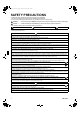
01_EN_3P132003-3N.fm Page 2 Tuesday, December 5, 2006 1:29 PM ACCESSORIES Clamp metal Insulation for fitting 1 pc. 1 each Washer for Drain hose hanging bracket Sealing pad Large and small 3 pcs. 1 each (only for 50-60 type) 1 pc. Sealing material Clamp 2 pcs. 6 pcs. 8 pcs. 1 pc. Washer Screws for fixing plate duct flanges 1 set 1 set 4 pcs. 24 pcs.
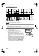
01_EN_3P132003-3N.fm Page 3 Tuesday, December 5, 2006 1:29 PM CHOOSING A SITE Select the signal receiver mounting location according to the following conditions: • Install the signal receiver, which has a built-in temperature sensor, near the intake vent where there is convection of air and it can get an accurate reading of the room’s temperature. If the intake vent is in another room or the unit cannot be installed near the intake vent for any other reason, install it 1.
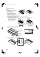
01_EN_3P132003-3N.fm Page 4 Tuesday, December 5, 2006 1:29 PM Mount chamber lid and air filter Protection net (1) (2) (accessory). Air inlet For bottom intake, replace the chamber lid and the protection net (only for 25-35 type) in the procedure listed in Fig. Chamber lid (1)Remove the protection net. Chamber lid Protection net (only for 25-35 type, 6 locations) Remove the chamber lid.
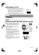
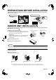
01_EN_3P132003-3N.fm Page 5 Tuesday, December 5, 2006 1:29 PM PREPARATIONS BEFORE INSTALLATION When two indoor units are installed in one room, one of the two wireless remote controllers can be easily set for another addresses. PCB in the indoor unit • Cut the jumper JA on PCB. Wireless remote controller • Cut the jumper J4.
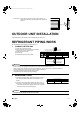
01_EN_3P132003-3N.fm Page 6 Tuesday, December 5, 2006 1:29 PM For heat pump: If your feet feel cold when using the heating function, it is recommended that the air discharge grille shown at below be attached. 45˚ (Adjustable angle) OUTDOOR UNIT INSTALLATION Install as described in the installation manual supplied with the outdoor unit. REFRIGERANT PIPING WORK See the installation manual supplied with the outdoor unit. 1. FLARING THE PIPE END 1) Cut the pipe end with a pipe cutter.
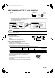
01_EN_3P132003-3N.fm Page 7 Tuesday, December 5, 2006 1:29 PM REFRIGERANT PIPING WORK 3) After the work is finished, make sure to check that there is no gas leak. Coat here with refrigeration machine oil Torque wrench Spanner Flare nut Piping union 4) After checking for gas leaks, be sure to insulate the pipe connections. • Insulate using the insulation for fitting included with the liquid and gas pipes. Besides, make sure the insulation for fitting on the liquid and gas piping has its seams facing up.
01_EN_3P132003-3N.fm Page 8 Tuesday, December 5, 2006 1:29 PM DRAIN PIPING WORK Caution Make sure all water is out before making the duct connection. Install the drain piping. Drain pipe connection hole • Make sure the drain works properly. • The diameter of the drain pipe should be greater than or equal to the diameter of the connecting pipe (vinyl tube; pipe size: 20mm; outer dimension: 26mm).
01_EN_3P132003-3N.fm Page 9 Tuesday, December 5, 2006 1:29 PM INSTALLING THE DUCT Connect the duct supplied in the field. Air inlet side • Attach the duct and intake-side flange (field supply). • Connect the flange to the main unit with accessory screws (in 16, 20 or 24 positions). • Wrap the intake-side flange and duct connection area with aluminum tape or something similar to prevent air escaping.
01_EN_3P132003-3N.fm Page 10 Tuesday, December 5, 2006 1:29 PM WIRING See the installation manual supplied with the outdoor unit. HOW TO CONNECT WIRINGS. • Wire only after removing the control box lid as shown in the Fig. Control box lid • Make sure to let a wire go through a wire penetration area. • After wiring, seal the wire and wire penetration area to prevent moisture and small creatures from the outside.
01_EN_3P132003-3N.fm Page 11 Tuesday, December 5, 2006 1:29 PM TRIAL OPERATION AND TESTING Trial operation and testing (1) Measure the supply voltage and make sure that it falls in the specified range. (2) Trial operation should be carried out in either cooling or heating mode. Trial operation from remote controller (1) Press ON/OFF button to turn on the system. (2) Simultaneously press center of TEMP button and MODE button. (3) Press MODE button twice.
00_CV_3P132003-3N.fm Page 2 Wednesday, November 29, 2006 6:40 PM Two-dimensional bar code is a code for manufacturing.