
Service manual

SiENBE12-522A
Drawings & Flow Charts v
Drawings & Flow Charts
A
anti-icing function in other rooms ..........................243
arc433a .................................................................201
automatic air flow control ........................................85
automatic operation.................................................87
auto-swing...............................................................84
B
buzzer pcb...............................................................72
C
capacitor voltage check.........................................251
compressor lock ....................................................220
compressor overload.............................................219
compressor protection function .............................105
control pcb............................................ 73
, 75, 79, 80
control pcb (indoor unit) ............................. 67
, 70, 72
cooling / heating mode lock...................................119
ct or related abnormality........................................230
D
dc fan lock .............................................................221
defrost control .......................................................109
diagnosis mode .....................................................202
discharge pipe control ...........................................106
discharge pipe temperature control.......................226
discharge pressure check .....................................249
display pcb ..................................... 67
, 72, 74, 76, 79
E
econo mode ............................................................90
electrical box temperature rise ..............................234
electronic expansion valve check..........................245
electronic expansion valve control ........................110
F
fan motor connector output check.........................244
fan motor or related abnormality
ac motor..........................................................210
dc motor..........................................................211
four way valve abnormality....................................224
four way valve performance check........................246
freeze-up protection control ......................... 107
, 217
freeze-up protection control or high pressure control..
208
frequency control...................................................103
frequency principle ..................................................82
function of thermistor...............................................98
cooling only model ..........................................100
heat pump model..............................................98
H
hall ic check...........................................................253
heating peak-cut control........................................107
high pressure control in cooling ............................227
home leave operation............................................. 93
I
indoor unit pcb abnormality .................................. 207
input current control ............................................. 106
input over current detection.................................. 222
installation condition check .................................. 248
insufficient gas ..................................................... 240
insufficient gas control.......................................... 114
intelligent eye ......................................................... 91
intelligent eye sensor ........................................... 298
intelligent eye sensor pcb........................... 67
, 70, 72
inverter features ..................................................... 83
inverter powerful operation..................................... 94
inverter units refrigerant system check................. 250
J
jumper settings ..................................................... 297
L
limit switch continuity check ................................. 244
location of operation lamp .................................... 198
low hz high pressure limit ..................................... 110
low-voltage detection ........................................... 242
M
main circuit electrolytic capacitor check ............... 252
main structural parts............................................... 97
mode hierarchy .................................................... 102
N
night set mode........................................................ 89
O
ol activation .......................................................... 219
on/off button on indoor unit .................................... 95
outdoor unit fan system check (with dc motor)..... 249
output over current detection ............................... 238
P
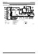
pcb ......................................................................... 69
piping diagrams
2amx52d2vmb ............................................... 307
2amx52dvmb ................................................. 307
2mxs52d2vmb ............................................... 307
2mxs52dvmb ................................................. 307
3amx52c2vmb ............................................... 307
3amx52cvmb ................................................. 307
3mks50d2vmb ............................................... 305
3mks50dvmb ................................................. 305
3mxs52d2vmb ............................................... 307
3mxs52dvmb ................................................. 307
4mks58d2vmb ............................................... 305
4mks58dvmb ................................................. 305
4mks75d2vmb ............................................... 306