
Service manual


SiENBE12-522A
Index iii
overload ................................................................114
overload relay........................................................282
P
p4 ..........................................................................232
pcb ................................................................267, 285
photocatalytic deodorizing filter...............................95
pi control................................................................104
piping diagrams.....................................................300
position sensor abnormality ..................................229
power failure recovery function .66, 68, 71, 73, 75, 77
power supply pcb ..............................................76, 77
power supply waveforms check ............................250
power transistor check ..........................................251
power-airflow dual flaps ..........................................84
powerful operation.................................................159
powerful operation mode.......................................118
preheating operation .............................................105
preparation before operation.................................144
pressure equalization control ................................112
preventing indoor freezing.....................................115
printed circuit board (pcb)
buzzer pcb ........................................................72
control pcb ....................................73, 75, 79, 286
control pcb (indoor unit) ........................67, 70, 72
control pcb (outdoor unit)..................................80
display pcb................................67, 72, 74, 76, 79
intelligent eye sensor pcb .....................67, 70, 72
inverter pcb.............................................269, 287
power supply pcb........................................76, 77
service monitor pcb ........................269, 285, 287
signal receiver pcb....................67, 70, 72, 76, 79
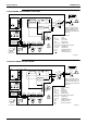
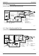
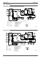
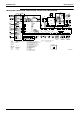
printed circuit board connector wiring diagram .......66
priority room setting...............................................118
problem symptoms and measures ........................200
programme dry function ..........................................86
propeller fans ........................................................259
R
radiation fin temperature rise ................................236
reactor ...................................................................273
remote controller ...................................................201
rth1 ........................................................66, 68, 71, 73
S
s1 ..........................................................66, 68, 71, 73
s20 ..................................................80, 262, 269, 282
s201 ........................................................................77
s202 ........................................................................77
s203 ........................................................................77
s204 ........................................................................77
s21 ..............66, 68, 71, 73, 75, 77, 80, 262, 269, 282
s22 ..................................................80, 262, 269, 282
s23 ............................................77, 80, 262, 269, 282
s24 ....................................................................75, 77
s25 ....................................................................75, 77
s26 ............................................66, 68, 71, 73, 75, 77
s27 ........................................................66, 68, 71, 75
s28 ....................................................................66, 71
s29 ....................................................................66, 71
s301 ........................................................................77
s302 ....................................................................... 77
s31 ............................................. 75, 77, 80, 269, 286
s32 ..................... 66, 68, 71, 73, 75, 77, 80, 269, 286
s33 ......................................................... 80, 269, 286
s35 ............................................................. 66, 68, 71
s36 ....................................................... 66, 68, 71, 75
s37 ................................................................... 71, 75
s38 ......................................................................... 71
s40 ................................................. 80, 263, 269, 282
s6 ................................................... 66, 68, 71, 75, 77
s7 ......................................................... 68, 73, 75, 77
s70 ....................................................................... 270
s71 ......................................................... 80, 269, 286
s8 ..................................................................... 71, 77
s80 ................................................. 80, 262, 269, 282
s90 ......................................... 80, 263, 269, 282, 291
s92 ......................................... 80, 263, 269, 282, 291
s93 ......................................... 80, 262, 269, 282, 291
safety precautions ................................................ 124
sc control.............................................................. 112
self-diagnosis digital display................................... 96
sensor malfunction detection ............................... 114
service check function .......................................... 201
service monitor pcb .............................. 269, 285, 287
shunt .................................................... 275, 292, 293
shutter drive motor / shutter limit switch abnormality .
214
signal receiver pcb ......................... 67, 70, 72, 76, 79
signal receiving sign............................................... 95
signal transmission error (between indoor and outdoor
units) ............................................................. 215
solenoid valve ...................................... 276, 292, 293
solenoid valve coil ................................................ 290
sound blanket............................................... 273, 289
specifications.......................................................... 20
sw1................................................. 66, 71, 73, 75, 77
sw2................................................................... 75, 77
sw4......................................................................... 77
sw7......................................................................... 68
T
target discharge pipe temperature control ........... 113
test run from the remote controller ....................... 296
thermistor ..................................... 269, 272, 282, 290
discharge pipe thermistor ........ 98, 100, 113, 291
gas pipe thermistor .......... 98, 100, 269, 282, 291
heat exchanger thermistor ............................. 291
indoor heat exchanger thermistor ............ 99, 101
liquid pipe thermistor................ 99, 269, 282, 291
outdoor air thermistor..................................... 291
outdoor heat exchanger thermistor.......... 98, 100
thermistor or related abnormality (indoor unit) ..... 213
thermistor or related abnormality (outdoor unit) ... 232
thermistor resistance check ................................. 247
thermostat control .................................................. 88
timer operation ..................................................... 170
titanium apatite photocatalytic air-purifying filter .... 95
troubleshooting..................................................... 191
indoor units .................................................... 205
outdoor units .................................................. 206
troubleshooting with the led indication ................. 199