
Service manual

Instruction SiENBE12-522A
142 System Configuration
■
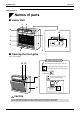
Outdoor Unit
■
■■
■
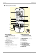
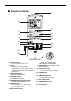
Indoor Unit
1. Photocatalytic deodorizing filter and
Air purifying filter:
•
These filters are attached to the inside of the air
filters.
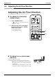
2. Air outlet
3. Display
4. Front grille
5. Louvres (vertical blades):
•
The louvres are inside of the air outlet.
6. Air inlet
7. Air filter
8. Flap (horizontal blade)
9. Operation lamp (green)
10. TIMER lamp (yellow)
11. HOME LEAVE lamp (red)
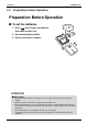
12. Indoor Unit ON/OFF switch:
•
Push this switch once to start operation.
Push once again to stop it.
•
The operation mode refers to the following
table.
•
This switch is useful when the remote controller
is missing.
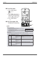
13. Signal receiver:
•
Signals are received from the remote controller .
•
When the unit receives a signal, you will hear a
short beep.
•
Operation start .............beep-beep
•
Settings changed..........beep
•
Operation stop ..............beeeeep
14. Air outlet selection switch
15. Room temperature sensor:
•
It senses the air temperature around the unit.
■
■■
■
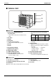
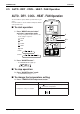
Outdoor Unit
16. Air inlet:
(Back and side)
17. Refrigerant piping and inter-unit cable
18. Drain hose
19. Earth terminal:
• It is inside of this cover.
20. Air outlet
Appearance of the outdoor unit may differ from some models.
17
18
19
20
16
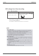
Mode
Temperature
setting
Air flow
rate
FVKS COOL
22
°
C
AUTO
FVXS AUTO
25
°
C
AUTO