SiENBE12-522A Service Manual Super Multi NX Serie D [Applied Models] !Inverter Multi : Cooling Only !Inverter Multi : Heat Pump
SiENBE12-522A SUPER MULTI NX D-Series !Cooling Only Indoor Unit FTKS20D(2)VMW(L)(9) FTKS25D(2)VMW(L)(9) FTKS35D(2)VMW(L)(9) CTKS50D(2)VMW(L) FTKS20CVMB(9) FTKS25CVMB(9)(8) FTKS35CVMB(9)(8) FTKS50BVMB FTKS60BVMB FTKS71BVMB FDKS25CVMB FDKS35CVMB CDKS50CVMB CDKS60CVMB FLKS25BVMB FLKS35BVMB FLKS50BVMB FLKS60BVMB FVKS25BVMB FVKS35BVMB FVKS50BVMB FTKS20DAVMW FTKS20DAVML FTKS20D3VMW FTKS20D3VML FTKS25DAVMW FTKS25DAVML FTKS25D3VMW FTKS25D3VML FTKS35DAVMW FTKS35DAVML FTKS35D3VMW FTKS35D3VML FTKS20CAVMB FTKS25
SiENBE12-522A !Heat Pump Indoor Unit FTXS20D(2)VMW(L)(9) FTXS25D(2)VMW(L)(9) FTXS35D(2)VMW(L)(9) CTXS50D(2)VMW(L) FTXS20CVMB(9) FTXS25CVMB(9)(8) FTXS35CVMB(9)(8) FTXS50BVMB FTXS60BVMB FTXS71BVMB ATXS20DVMB ATXS25DVMB ATXS35DVMB ATXS20CVMB(9) ATXS25CVMB(9) ATXS35CVMB(9) ATXS50DVMB ATXS50CVMB FDXS25CVMB FDXS35CVMB CDXS50CVMB CDXS60CVMB FLXS25BVMB FLXS35BVMB FLXS50BVMB FLXS60BVMB FVXS25BVMB FVXS35BVMB FVXS50BVMB FTXS20DAVMW FTXS20DAVML FTXS20D3VMW FTXS20D3VML FTXS25DAVMW FTXS25DAVML FTXS25D3VMW FTXS25D3VM
SiENBE12-522A 1.3 Indoor Units - Heat Pump.......................................................................40 1.4 Outdoor Units - Heat Pump ....................................................................58 Part 3 Printed Circuit Board Connector Wiring Diagram65 1. Printed Circuit Board Connector Wiring Diagram..................................66 1.1 1.2 1.3 1.4 1.5 Wall Mounted Type ................................................................................66 Duct Connected Type..........
SiENBE12-522A Part 5 System Configuration121 1. System Configuration..........................................................................122 1.1 Operation Instructions ..........................................................................122 2. Instruction............................................................................................123 2.1 2.2 2.3 2.4 2.5 2.6 2.7 2.8 2.9 2.10 2.11 2.12 2.13 2.14 2.15 Manual Contents and Reference Page ...............................................
SiENBE12-522A 5.20 5.21 5.22 5.23 5.24 5.25 5.26 Thermistor or Related Abnormality (Outdoor Unit)...............................232 Electrical Box Temperature Rise..........................................................234 Radiation Fin Temperature Rise ..........................................................236 Output Over Current Detection.............................................................238 Insufficient Gas..................................................................................
SiENBE12-522A 2. Wiring Diagrams..................................................................................309 2.1 Indoor Units ..........................................................................................309 2.2 Outdoor Units .......................................................................................
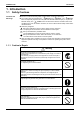
SiENBE12-522A Introduction 1. Introduction 1.1 Safety Cautions Cautions and Warnings " Be sure to read the following safety cautions before conducting repair work. " The caution items are classified into “ Warning” and “ Caution”. The “ Warning” items are especially important since they can lead to death or serious injury if they are not followed closely. The “ Caution” items can also lead to serious accidents under some conditions if they are not followed.
Introduction SiENBE12-522A Caution Do not repair the electrical components with wet hands. Working on the equipment with wet hands can cause an electrical shock. Do not clean the air conditioner by splashing water. Washing the unit with water can cause an electrical shock. Be sure to provide the grounding when repairing the equipment in a humid or wet place, to avoid electrical shocks. Be sure to turn off the power switch and unplug the power cable when cleaning the equipment.
SiENBE12-522A Introduction Warning Be sure to use an exclusive power circuit for the equipment, and follow the technical standards related to the electrical equipment, the internal wiring regulations and the instruction manual for installation when conducting electrical work. Insufficient power circuit capacity and improper electrical work can cause an electrical shock or fire. Be sure to use the specified cable to connect between the indoor and outdoor units.
Introduction SiENBE12-522A Warning Do not use a joined power cable or extension cable, or share the same power outlet with other electrical appliances, since it can cause an electrical shock, excessive heat generation or fire. Caution Check to see if the parts and wires are mounted and connected properly, and if the connections at the soldered or crimped terminals are secure. Improper installation and connections can cause excessive heat generation, fire or an electrical shock.
SiENBE12-522A Part 1 List of Functions 1. List of Functions ......................................................................................2 1.1 Cooling Only Models ................................................................................2 1.2 Heat Pump Models...................................................................................
List of Functions SiENBE12-522A 1.
FDKS25·35CVMB CDKS50·60CVMB FTKS50-71BVMB FDKS25·35CVMB CDKS50·60CVMB Inverter (with Inverter Power Control) # # # Health & Clean Air Purifying Filter with Bacteriostatic & Virustatic Functions — — — Operation Limit for Cooling (°CDB) — — — Photocatalytic Deodorizing Filter — — — Operation Limit for Heating (°CWB) — — — Air Purifying Filter with Photocatalytic Deodorizing Function # — — PAM Control — — — Titanium Apatite Photocatalytic Air-Purifying Filter — — — Oval Scr
Compressor Comfortable Airflow Comfort Control Operation Lifestyle Convenience 3MKS50D(2)VMB 4MKS58·75D(2)VMB 4MKS90DVMB # Operation Limit for Cooling (°CDB) — — –10 ~ 46 Operation Limit for Heating (°CWB) — — PAM Control — Air Purifying Filter with Bacteriostatic & Virustatic Functions # # — Photocatalytic Deodorizing Filter # # — — Air Purifying Filter with — Photocatalytic Deodorizing Function — — — # Titanium Apatite Photocatalytic Air-Purifying Filter — — Category Heal
FTKS20-35DAVMW(L) FTKS20-35D3VMW(L) FTKS20-35CAVMB # # — — — Air Purifying Filter with Bacteriostatic, Virustatic Functions — — — Operation Limit for Heating (°CWB) — — — Photocatalytic Deodorizing Filter — — — — — Air Purifying Filter with Photocatalytic Deodorizing Function — — # Titanium Apatite Photocatalytic Air-Purifying Filter # # — # PAM Control Compressor Comfortable Airflow Comfort Control Operation Lifestyle Convenience — FTKS20-35CAVMB # Operation Limit for
FTKS71BAVMB FDKS25·35CAVMB FDKS25·35CAVMB Inverter (with Inverter Power Control) # # Air Purifying Filter with Bacteriostatic & Virustatic Functions — — Operation Limit for Cooling (°CDB) — — Photocatalytic Deodorizing Filter — — Operation Limit for Heating (°CWB) — — Air Purifying Filter with Photocatalytic Deodorizing Function # — PAM Control — — Titanium Apatite Photocatalytic Air-Purifying Filter — — Oval Scroll Compressor — — Mold Proof Air Filter # # Swing Compressor
Compressor Comfortable Airflow Comfort Control Operation Lifestyle Convenience Functions FVKS25-50BAVMB 4MKS75D3VMB 4MKS90DAVMB 4MKS75D3VMB 4MKS90DAVMB # # Operation Limit for Cooling (°CDB) — — –10 ~ 46 Operation Limit for Heating (°CWB) — — — Air Purifying Filter with Photocatalytic Deodorizing Function — — — PAM Control — — # Titanium Apatite Photocatalytic Air-Purifying Filter — — Functions FLKS25-60BAVMB FVKS25-50BAVMB Inverter (with Inverter Power Control) # Category
List of Functions FTXS20-35CVMB(9)(8) # # # Operation Limit for Cooling (°CDB) — — — Air Purifying Filter with Bacteriostatic, Virustatic Functions — — — Operation Limit for Heating (°CWB) — — — Photocatalytic Deodorizing Filter — — — — — Air Purifying Filter with Photocatalytic Deodorizing Function — — # Titanium Apatite Photocatalytic Air-Purifying Filter # # — # PAM Control Compressor Comfortable Airflow Comfort Control Operation Lifestyle Convenience Category Functi
FDXS25·35CVMB CDXS50·60CVMB FTXS50-71BVMB FDXS25·35CVMB CDXS50·60CVMB Inverter (with Inverter Power Control) # # Health & # Clean Air Purifying Filter with Bacteriostatic & Virustatic Functions — — — Operation Limit for Cooling (°CDB) — — — Photocatalytic Deodorizing Filter — — — # — — — — Category Basic Function Compressor Comfortable Airflow Comfort Control Operation Lifestyle Convenience List of Functions FTXS50-71BVMB SiENBE12-522A Functions Category Functions Oper
Compressor Comfortable Airflow Comfort Control Operation Lifestyle Convenience # Operation Limit for Cooling (°CDB) — Air Purifying Filter with Bacteriostatic & Virustatic Functions # # — Photocatalytic Deodorizing Filter # # — — — — Category Health & Clean Functions Operation Limit for Heating (°CWB) — — Air Purifying Filter with Photocatalytic Deodorizing Function PAM Control — — Titanium Apatite Photocatalytic Air-Purifying Filter Oval Scroll Compressor — — Mold Proof Air
Basic Function Compressor Comfortable Airflow Comfort Control Operation Lifestyle Convenience Functions Inverter (with Inverter Power Control) # Category Health & Clean Functions 2MXS52D(2)VMB 3MXS52D(2)VMB 4MXS68D(2)VMB 4MXS80DVMB Category List of Functions 2MXS52D(2)VMB 3MXS52D(2)VMB 4MXS68D(2)VMB 4MXS80DVMB SiENBE12-522A Air Purifying Filter with Bacteriostatic & Virustatic Functions — Operation Limit for Cooling (°CDB) –10 ~ 46 Photocatalytic Deodorizing Filter — Operation Limit f
ATXS20-35DVMB ATXS20-35CVMB(9) Inverter (with Inverter Power Control) # # Operation Limit for Cooling (°CDB) H1 — — Air Purifying Filter with Bacteriostatic, Virustatic Functions — — Operation Limit for Heating (°CWB) — — Photocatalytic Deodorizing Filter — — — Air Purifying Filter with Photocatalytic Deodorizing Function # # Titanium Apatite Photocatalytic Air-Purifying Filter — — Functions Basic Function PAM Control Compressor Comfortable Airflow Comfort Control Operation Li
Functions Basic Function Comfortable Airflow Comfort Control Operation Lifestyle Convenience Inverter (with Inverter Power Control) # — Air Purifying Filter with Bacteriostatic, Virustatic Functions — Operation Limit for Heating (°CWB) — Photocatalytic Deodorizing Filter — — Air Purifying Filter with Photocatalytic Deodorizing Function # Oval Scroll Compressor — Swing Compressor — Rotary Compressor Reluctance DC Motor Power-Airflow Flap Longlife Filter — Ultra-Longlife Filter (Option
Compressor Comfortable Airflow Comfort Control # # Operation Limit for Cooling (°CDB) — –10~ 46 Operation Limit for Heating (°CWB) — –15~ 15.
FTXS20-35D3VMW(L) FTXS20-35CAVMB # # # Operation Limit for Cooling (°CDB) — — — Air Purifying Filter with Bacteriostatic, Virustatic Functions — — — Operation Limit for Heating (°CWB) — — — Photocatalytic Deodorizing Filter — — — — — Air Purifying Filter with Photocatalytic Deodorizing Function — — # Titanium Apatite Photocatalytic Air-Purifying Filter # # — # PAM Control Compressor Comfortable Airflow Comfort Control Operation Lifestyle Convenience — FTXS20-35CAVMB FT
FTXS71BAVMB FDXS25·35CAVMB # # Health & Clean Air Purifying Filter with Bacteriostatic & Virustatic Functions — — Operation Limit for Cooling (°CDB) — — Photocatalytic Deodorizing Filter — — # — — Compressor Comfortable Airflow Comfort Control Operation Lifestyle Convenience Functions Category Functions Operation Limit for Heating (°CWB) — — Air Purifying Filter with Photocatalytic Deodorizing Function PAM Control — — Titanium Apatite Photocatalytic Air-Purifying Filter — Ova
Compressor Comfortable Airflow Comfort Control Operation Lifestyle Convenience FVXS25-50BAVMB 4MXS68D3VMB 4MXS80DAVMB 4MXS68D3VMB 4MXS80DAVMB # # # Operation Limit for Cooling (°CDB) — — Operation Limit for Heating (°CWB) — PAM Control — Functions FLXS25-60BAVMB FVXS25-50BAVMB Inverter (with Inverter Power Control) Category Basic Function List of Functions FLXS25-60BAVMB SiENBE12-522A Air Purifying Filter with Bacteriostatic & Virustatic Functions # # — –10 ~ 46 Photocatalyti
Functions Basic Function Comfortable Airflow Comfort Control Operation Lifestyle Convenience Inverter (with Inverter Power Control) # — Air Purifying Filter with Bacteriostatic, Virustatic Functions — Operation Limit for Heating (°CWB) — Photocatalytic Deodorizing Filter — — Air Purifying Filter with Photocatalytic Deodorizing Function # Titanium Apatite Photocatalytic Air-Purifying Filter — # Oval Scroll Compressor — Swing Compressor — Rotary Compressor — Mold Proof Air Filter Rel
SiENBE12-522A Part 2 Specifications 1. Specifications ........................................................................................20 1.1 1.2 1.3 1.4 Specifications Indoor Units - Cooling Only ....................................................................20 Outdoor Units - Cooling Only .................................................................35 Indoor Units - Heat Pump.......................................................................40 Outdoor Units - Heat Pump .............
Specifications SiENBE12-522A 1. Specifications 1.1 Indoor Units - Cooling Only Wall Mounted Type 50Hz 230V Model Rated Capacity Front Panel Color Air Flow Rates m³/min (cfm) Type Motor Output Speed Air Direction Control Air Filter Running Current (Rated) Power Consumption (Rated) Power Factor Temperature Control Dimensions (H×W×D) Packaged Dimensions (H×W×D) Weight Gross Weight Operation H/L/SL Sound Sound Power H Heat Insulation Liquid Gas Piping Connection Drain Drawing No.
SiENBE12-522A Specifications 50Hz 230V Model Rated Capacity Front Panel Color Air Flow Rates m³/min (cfm) Type Motor Output Speed Air Direction Control Air Filter Running Current (Rated) Power Consumption (Rated) Power Factor Temperature Control Dimensions (H×W×D) Packaged Dimensions (H×W×D) Weight Gross Weight Operation H/L/SL Sound Sound Power H Heat Insulation Liquid Gas Piping Connection Drain Drawing No. Fan mm mm kg kg FTKS25DVMW(9) 2.5kW Class White 8.7 (307) 6.7 (237) 4.7 (166) 3.
Specifications SiENBE12-522A 50Hz 230V Model Rated Capacity Front Panel Color Air Flow Rates m³/min (cfm) Type Motor Output Speed Air Direction Control Air Filter Running Current (Rated) Power Consumption (Rated) Power Factor Temperature Control Dimensions (H×W×D) Packaged Dimensions (H×W×D) Weight Gross Weight Operation H/L/SL Sound Sound Power H Heat Insulation Liquid Gas Piping Connection Drain Drawing No. Fan mm mm kg kg FTKS35DVMW(9) 3.5kW Class White 8.9 (314) 6.9 (244) 4.8 (169) 4.
SiENBE12-522A Specifications 50Hz 230V Model Rated Capacity Front Panel Color Air Flow Rates m³/min (cfm) Type Motor Output Speed Air Direction Control Air Filter Running Current (Rated) Power Consumption (Rated) Power Factor Temperature Control Dimensions (H×W×D) Packaged Dimensions (H×W×D) Weight Gross Weight Operation H/L/SL Sound Sound Power H Heat Insulation Liquid Gas Piping Connection Drain Drawing No. Fan mm mm kg kg CTKS50D(2)VMW 5.0kW Class White 11.4 (402) 9.3 (328) 7.1 (251) 6.
Specifications SiENBE12-522A 50Hz 230V Model Rated Capacity Front Panel Color Air Flow Rates m³/min (cfm) Type Motor Output Speed Air Direction Control Air Filter Running Current (Rated) Power Consumption (Rated) Power Factor Temperature Control Dimensions (H×W×D) Packaged Dimensions (H×W×D) Weight Gross Weight Operation H/M/L/SL Sound Sound Power H Heat Insulation Liquid Gas Piping Connection Drain Drawing No. Fan mm mm kg kg FTKS35CVMB(9)(8) 3.5kW Class White 7.7 (272) 6.0 (212) 4.4 (155) 3.
SiENBE12-522A Specifications 50Hz 230V Model Rated Capacity Front Panel Color Air Flow Rates m³/min (cfm) Type Motor Output Speed Air Direction Control Air Filter Running Current (Rated) Power Consumption (Rated) Power Factor Temperature Control Dimensions (H×W×D) Packaged Dimensions (H×W×D) Weight Gross Weight Operation H/L/SL Sound Sound Power H Heat Insulation Liquid Gas Piping Connection Drain Drawing No. Fan mm mm kg kg FTKS20DAVMW 2.0kW Class White 8.7 (307) 6.7 (237) 4.7 (166) 3.
Specifications SiENBE12-522A 50Hz 230V Model Rated Capacity Front Panel Color Air Flow Rates m³/min (cfm) Type Motor Output Speed Air Direction Control Air Filter Running Current (Rated) Power Consumption (Rated) Power Factor Temperature Control Dimensions (H×W×D) Packaged Dimensions (H×W×D) Weight Gross Weight Operation H/L/SL Sound Sound Power H Heat Insulation Liquid Gas Piping Connection Drain Drawing No. Fan mm mm kg kg FTKS25DAVMW 2.5kW Class White 8.7 (307) 6.7 (237) 4.7 (166) 3.
SiENBE12-522A Specifications 50Hz 230V Model Rated Capacity Front Panel Color Air Flow Rates m³/min (cfm) Type Motor Output Speed Air Direction Control Air Filter Running Current (Rated) Power Consumption (Rated) Power Factor Temperature Control Dimensions (H×W×D) Packaged Dimensions (H×W×D) Weight Gross Weight Operation H/L/SL Sound Sound Power H Heat Insulation Liquid Gas Piping Connection Drain Drawing No. Fan mm mm kg kg FTKS35DAVMW 3.5kW Class White 8.9 (314) 6.9 (244) 4.8 (169) 4.
Specifications SiENBE12-522A 50Hz 230V Model Rated Capacity Front Panel Color Air Flow Rates m³/min (cfm) Type Motor Output Speed Air Direction Control Air Filter Running Current (Rated) Power Consumption (Rated) Power Factor Temperature Control Dimensions (H×W×D) Packaged Dimensions (H×W×D) Weight Gross Weight Operation H/M/L/SL Sound Sound Power H Heat Insulation Liquid Gas Piping Connection Drain Drawing No. Fan mm mm kg kg FTKS20CAVMB 2.0kW Class White 7.7 (272) 5.9 (208) 4.2 (148) 3.
SiENBE12-522A Specifications Duct Connected Type 50Hz 230V Model Rated Capacity FDKS25CVMB 2.5kW Class — — mm mm kg kg 9.5 (335) 8.8 (311) 8.0 (282) 6.7 (237) Sirocco Fan 62 5 Steps, Silent, Auto Removable-Washable-Mildew Proof 0.47 100 92.5 Microcomputer Control 200×900×620 266×1,106×751 25 31 10.0 (353) 9.3 (328) 8.5 (300) 7.0 (247) Sirocco Fan 62 5 Steps, Silent, Auto Removable-Washable-Mildew Proof 0.47 100 92.
Specifications SiENBE12-522A 50Hz 230V Model Rated Capacity FDKS25CAVMB 2.5kW Class — — mm mm kg kg 9.5 (335) 8.8 (311) 8.0 (282) 6.7 (237) Sirocco Fan 62 5 Steps, Silent, Auto Removable-Washable-Mildew Proof 0.47 100 92.5 Microcomputer Control 200×900×620 266×1,106×751 25 31 10.0 (353) 9.3 (328) 8.5 (300) 7.0 (247) Sirocco Fan 62 5 Steps, Silent, Auto Removable-Washable-Mildew Proof 0.47 100 92.
SiENBE12-522A Specifications Floor / Ceiling Suspended Dual Type 50Hz 230V Model Rated Capacity Front Panel Color Air Flow Rates m³/min (cfm) Type Motor Output Speed Air Direction Control Air Filter Running Current (Rated) Power Consumption (Rated) Power Factor Temperature Control Dimensions (H×W×D) Packaged Dimensions (H×W×D) Weight Gross Weight Operation H/M/L/SL Sound Sound Power H Heat Insulation Liquid Gas Piping Connection Drain Drawing No. Fan mm mm kg kg FLKS25BVMB 2.5kW Class Almond White 7.
Specifications SiENBE12-522A Power Factor Temperature Control Dimensions (H×W×D) Packaged Dimensions (H×W×D) Weight Gross Weight Operation H/M/L/SL Sound Sound Power H Heat Insulation Liquid Gas Piping Connection Drain Drawing No. % mm mm kg kg 94.6 Microcomputer Control 490×1,050×200 566×1,100×280 16 22 94.2 Microcomputer Control 490×1,050×200 566×1,100×280 16 22 dBA 37/34/31/28 38/35/32/29 dBA 53 Both Liquid and Gas Pipes φ 6.4 φ 9.5 φ18.0 3D050862 54 Both Liquid and Gas Pipes φ 6.4 φ 9.5 φ18.
SiENBE12-522A Specifications Floor Standing Type 50Hz 230V Model Rated Capacity Front Panel Color Air Flow Rates m³/min (cfm) Type Motor Output Speed Air Direction Control Air Filter Running Current (Rated) Power Consumption (Rated) Power Factor Temperature Control Dimensions (H×W×D) Packaged Dimensions (H×W×D) Weight Gross Weight Operation H/M/L/SL Sound Sound Power H Heat Insulation Liquid Gas Piping Connection Drain Drawing No. Fan mm mm kg kg FVKS25BVMB 2.5kW Class Almond White 8.1 (286) 6.
Specifications SiENBE12-522A Power Consumption (Rated) Power Factor Temperature Control Dimensions (H×W×D) Packaged Dimensions (H×W×D) Weight Gross Weight Operation H/M/L/SL Sound Sound Power H Heat Insulation Liquid Gas Piping Connection Drain Drawing No. W % mm mm kg kg 32 99.4 Microcomputer Control 600×650×195 714×770×294 13 19 32 99.4 Microcomputer Control 600×650×195 714×770×294 13 19 dBA 38/32/26/23 39/33/27/24 dBA 54 Both Liquid and Gas Pipes φ 6.4 φ 9.5 φ18.
SiENBE12-522A 1.2 Specifications Outdoor Units - Cooling Only 50Hz 230V Model Cooling Capacity kW Power Consumption W Running Current A Casing Color Type Compressor Model Motor Output Model Refrigerant Oil Charge Type Refrigerant Charge W L m³/min Air Flow Rates cfm Fan Type Motor Output Running Current Power Consumption Starting Current Dimensions (H×W×D) Packaged Dimensions (H×W×D) Weight Gross Weight Operation Sound Sound Power Liquid Piping Connection Gas Drain Heat Insulation No.
Specifications SiENBE12-522A 50Hz 230V Model Cooling Capacity kW Power Consumption W Running Current Casing Color A Type Compressor Model Motor Output Model Refrigerant Oil Charge Type Refrigerant Charge W L m³/min Air Flow Rates cfm Fan Type Motor Output Running Current Power Consumption Starting Current Dimensions (H×W×D) Packaged Dimensions (H×W×D) Weight Gross Weight Operation Sound Sound Power Liquid Gas Piping Connection Drain Heat Insulation No. of Wiring Connection Max.
SiENBE12-522A Specifications 50Hz 230V Model Cooling Capacity kW Power Consumption W Running Current Casing Color A Type Compressor Model Motor Output Model Refrigerant Oil Charge Type Refrigerant Charge W L m³/min Air Flow Rates cfm Fan Type Motor Output Running Current Power Consumption Starting Current Dimensions (H×W×D) Packaged Dimensions (H×W×D) Weight Gross Weight Operation Sound Sound Power Liquid Gas Piping Connection Drain Heat Insulation No. of Wiring Connection Max.
Specifications SiENBE12-522A 50Hz 230V Model 4MKS75D2VMB Cooling Capacity kW Power Consumption W Running Current Casing Color A Type Compressor Model Motor Output Model Refrigerant Oil Charge Type Refrigerant Charge Ivory White Hermetically Sealed Swing Type 2YC45BXD 1,380 FVC50K 0.75 R-410A 2.3 51 45 1,801 1,589 Propeller 53 H: 0.33 / L: 0.25 H: 68 / L: 46 8.7 735×936×300 784×992×390 58 64 48 61 φ 6.4×4 φ9.5×2, φ12.7×1, φ15.9×1 φ18.
SiENBE12-522A Specifications 50Hz 230V Model Cooling Capacity kW Power Consumption W Running Current Casing Color A Type Compressor Model Motor Output Model Refrigerant Oil Charge Type Refrigerant Charge W L m³/min Air Flow Rates cfm Fan Type Motor Output Running Current Power Consumption Starting Current Dimensions (H×W×D) Packaged Dimensions (H×W×D) Weight Gross Weight Operation Sound Sound Power Liquid Gas Piping Connection Drain Heat Insulation No. of Wiring Connection Max.
Specifications 1.3 SiENBE12-522A Indoor Units - Heat Pump Wall Mounted Type 50Hz 230V FTXS20DVMW(9) Model Cooling Rated Capacity Front Panel Color Air Flow Rates m³/min (cfm) Type Motor Output Speed Air Direction Control Air Filter Running Current (Rated) Power Consumption (Rated) Power Factor Temperature Control Dimensions (H×W×D) Packaged Dimensions (H×W×D) Weight Gross Weight Operation H/L/SL Sound Sound Power H Heat Insulation Liquid Gas Piping Connection Drain Drawing No.
SiENBE12-522A Specifications 50Hz 230V FTXS25DVMW(9) Model Cooling Rated Capacity Front Panel Color Air Flow Rates m³/min (cfm) Type Motor Output Speed Air Direction Control Air Filter Running Current (Rated) Power Consumption (Rated) Power Factor Temperature Control Dimensions (H×W×D) Packaged Dimensions (H×W×D) Weight Gross Weight Operation H/L/SL Sound Sound Power H Heat Insulation Liquid Gas Piping Connection Drain Drawing No. H M L SL W Steps A W % mm mm kg kg 8.7 (307) 6.7 (237) 4.7 (166) 3.
Specifications SiENBE12-522A 50Hz 230V FTXS35DVMW(9) Model Cooling Rated Capacity Front Panel Color Air Flow Rates m³/min (cfm) Type Motor Output Speed Air Direction Control Air Filter Running Current (Rated) Power Consumption (Rated) Power Factor Temperature Control Dimensions (H×W×D) Packaged Dimensions (H×W×D) Weight Gross Weight Operation H/L/SL Sound Sound Power H Heat Insulation Liquid Gas Piping Connection Drain Drawing No. H M L SL W Steps A W % mm mm kg kg 8.9 (314) 6.9 (244) 4.8 (169) 4.
SiENBE12-522A Specifications 50Hz 230V CTXS50D(2)VMW Model Cooling Rated Capacity Front Panel Color Air Flow Rates m³/min (cfm) Type Motor Output Speed Air Direction Control Air Filter Running Current (Rated) Power Consumption (Rated) Power Factor Temperature Control Dimensions (H×W×D) Packaged Dimensions (H×W×D) Weight Gross Weight Operation H/L/SL Sound Sound Power H Heat Insulation Liquid Gas Piping Connection Drain Drawing No. H M L SL W Steps A W % mm mm kg kg Heating 11.4 (402) 9.3 (328) 7.
Specifications SiENBE12-522A 50Hz 230V FTXS35CVMB(9)(8) Model Cooling Rated Capacity Front Panel Color Air Flow Rates m³/min (cfm) Type Motor Output Speed Air Direction Control Air Filter Running Current (Rated) Power Consumption (Rated) Power Factor Temperature Control Dimensions (H×W×D) Packaged Dimensions (H×W×D) Weight Gross Weight Operation H/M/L/SL Sound Sound Power H Heat Insulation Liquid Gas Piping Connection Drain Drawing No. H M L SL W Steps A W % mm mm kg kg 7.7 (272) 6.0 (212) 4.
SiENBE12-522A Specifications 50Hz 230V ATXS20DVMB Model Cooling Rated Capacity Front Panel Color Air Flow Rates m³/min (cfm) Type Motor Output Speed Air Direction Control Air Filter Running Current (Rated) Power Consumption (Rated) Power Factor Temperature Control Dimensions (H×W×D) Packaged Dimension (H×W×D) Weight Gross Weight H M L SL W Steps A W % Operation Sound dBA Sound Power Heat Insulation dBA mm mm kg kg H M L SL H Liquid Gas Drain mm mm mm Drawing No. 7.7 (272) 5.9 (208) 4.
Specifications SiENBE12-522A 50Hz 230V ATXS20CVMB(9) Model Cooling Rated Capacity Front Panel Color Air Flow Rates m³/min (cfm) Type Motor Output Speed Air Direction Control Air Filter Running Current (Rated) Power Consumption (Rated) Power Factor Temperature Control Dimensions (H×W×D) Packaged Dimension (H×W×D) Weight Gross Weight H M L SL W Steps A W % Operation Sound dBA Sound Power Heat Insulation dBA mm mm kg kg H M L SL H Liquid Gas Drain mm mm mm Drawing No. 7.7 (272) 5.9 (208) 4.
SiENBE12-522A Specifications 50Hz 230V FTXS20DAVMW Model Cooling Rated Capacity Front Panel Color Air Flow Rates m³/min (cfm) Type Motor Output Speed Air Direction Control Air Filter Running Current (Rated) Power Consumption (Rated) Power Factor Temperature Control Dimensions (H×W×D) Packaged Dimensions (H×W×D) Weight Gross Weight Operation H/L/SL Sound Sound Power H Heat Insulation Liquid Gas Piping Connection Drain Drawing No. H M L SL W Steps A W % mm mm kg kg 8.7 (307) 6.7 (237) 4.7 (166) 3.
Specifications SiENBE12-522A 50Hz 230V FTXS25DAVMW Model Cooling Rated Capacity Front Panel Color Air Flow Rates m³/min (cfm) Type Motor Output Speed Air Direction Control Air Filter Running Current (Rated) Power Consumption (Rated) Power Factor Temperature Control Dimensions (H×W×D) Packaged Dimensions (H×W×D) Weight Gross Weight Operation H/L/SL Sound Sound Power H Heat Insulation Liquid Gas Piping Connection Drain Drawing No. H M L SL W Steps A W % mm mm kg kg 8.7 (307) 6.7 (237) 4.7 (166) 3.
SiENBE12-522A Specifications 50Hz 230V FTXS35DAVMW Model Cooling Rated Capacity Front Panel Color Air Flow Rates m³/min (cfm) Type Motor Output Speed Air Direction Control Air Filter Running Current (Rated) Power Consumption (Rated) Power Factor Temperature Control Dimensions (H×W×D) Packaged Dimensions (H×W×D) Weight Gross Weight Operation H/L/SL Sound Sound Power H Heat Insulation Liquid Gas Piping Connection Drain Drawing No. H M L SL W Steps A W % mm mm kg kg 8.9 (314) 6.9 (244) 4.8 (169) 4.
Specifications SiENBE12-522A 50Hz 230V FTXS20CAVMB Model Cooling Rated Capacity Front Panel Color Air Flow Rates m³/min (cfm) Type Motor Output Speed Air Direction Control Air Filter Running Current (Rated) Power Consumption (Rated) Power Factor Temperature Control Dimensions (H×W×D) Packaged Dimensions (H×W×D) Weight Gross Weight Operation H/M/L/SL Sound Sound Power H Heat Insulation Liquid Gas Piping Connection Drain Drawing No. H M L SL W Steps A W % mm mm kg kg 7.7 (272) 5.9 (208) 4.2 (148) 3.
SiENBE12-522A Specifications 50Hz 230V ATXS20DAVMB Model Cooling Rated Capacity Front Panel Color Air Flow Rates m³/min (cfm) Type Motor Output Speed Air Direction Control Air Filter Running Current (Rated) Power Consumption (Rated) Power Factor Temperature Control Dimensions (H×W×D) Packaged Dimension (H×W×D) Weight Gross Weight H M L SL W Steps A W % Operation Sound dBA Sound Power Heat Insulation dBA mm mm kg kg H M L SL H Liquid Gas Drain mm mm mm Drawing No. 7.7 (272) 5.9 (208) 4.
Specifications SiENBE12-522A Duct Connected Type 50Hz 230V FDXS25CVMB Model Cooling Rated Capacity Front Panel Color m³/min (cfm) Type Motor Output Speed H M L SL W Steps A W % mm mm kg kg dBA Pa mm mm mm 9.5 (335) 8.8 (311) 8.0 (282) 6.7 (237) — 9.5 (335) 8.8 (311) 8.0 (282) 6.7 (237) Sirocco Fan 62 5 Steps, Silent, Auto Removable-Washable-Mildew Proof 0.47 0.47 100 100 92.5 92.5 Microcomputer Control 200×900×620 266×1,106×751 25 31 35/33/31/29 35/33/31/29 40 Both Liquid and Gas Pipes φ 6.4 φ 9.
SiENBE12-522A Specifications 50Hz 230V FDXS25CAVMB Model Cooling Rated Capacity Cooling 2.5kW Class m³/min (cfm) Air Flow Rates Type Motor Output Speed W Steps Air Filter Running Current (Rated) Power Consumption (Rated) Power Factor Temperature Control Dimensions (H×W×D) Packaged Dimensions (H×W×D) Weight Gross Weight Operation H/M/L/SL Sound External Static Pressure Heat Insulation Liquid Gas Piping Connection Drain Drawing No.
Specifications SiENBE12-522A Floor / Ceiling Suspended Dual Type 50Hz 230V FLXS25BVMB Model Cooling Rated Capacity Front Panel Color Air Flow Rates m³/min (cfm) Type Motor Output Speed Air Direction Control Air Filter Running Current (Rated) Power Consumption (Rated) Power Factor Temperature Control Dimensions (H×W×D) Packaged Dimensions (H×W×D) Weight Gross Weight Operation H/M/L/SL Sound Sound Power H Heat Insulation Liquid Gas Piping Connection Drain Drawing No.
SiENBE12-522A Specifications 50Hz 230V FLXS25BAVMB Model Cooling Rated Capacity Front Panel Color Air Flow Rates m³/min (cfm) Type Motor Output Speed Air Direction Control Air Filter Running Current (Rated) Power Consumption (Rated) Power Factor Temperature Control Dimensions (H×W×D) Packaged Dimensions (H×W×D) Weight Gross Weight Operation H/M/L/SL Sound Sound Power H Heat Insulation Liquid Gas Piping Connection Drain Drawing No. H M L SL W Steps A W % mm mm kg kg 7.6 (268) 6.8 (240) 6.0 (212) 5.
Specifications SiENBE12-522A Floor Standing Type 50Hz 230V FVXS25BVMB Model Cooling Rated Capacity Front Panel Color Air Flow Rates FVXS35BVMB Heating 2.5kW Class Almond White m³/min (cfm) Type Motor Output Speed Air Direction Control Air Filter Running Current (Rated) Power Consumption (Rated) Power Factor Temperature Control Dimensions (H×W×D) Packaged Dimensions (H×W×D) Weight Gross Weight Operation H/M/L/SL Sound Sound Power H Heat Insulation Liquid Gas Piping Connection Drain Drawing No.
SiENBE12-522A Specifications Air Filter Running Current (Rated) Power Consumption (Rated) Power Factor Temperature Control Dimensions (H×W×D) Packaged Dimensions (H×W×D) Weight Gross Weight Operation H/M/L/SL Sound Sound Power H Heat Insulation Liquid Gas Piping Connection Drain Drawing No. A W % mm mm kg kg Removable-Washable-Mildew Proof 0.14 0.14 32 32 99.4 99.
Specifications 1.
SiENBE12-522A Specifications 50Hz 230V 4MXS68DVMB Model Cooling Cooling Capacity kW Power Consumption W Running Current Casing Color A Type Compressor Model Motor Output Model Refrigerant Oil Charge Type Refrigerant Charge W L m³/min Air Flow Rates cfm Fan Type Motor Output Running Current Power Consumption Starting Current Dimensions (H×W×D) Packaged Dimensions (H×W×D) Weight Gross Weight Operation Sound Sound Power Liquid Gas Piping Connection Drain Heat Insulation No.
Specifications SiENBE12-522A 50Hz 230V 2AMX52DVMB Model Cooling Cooling Capacity kW Power Consumption W Running Current Casing Color A Type Compressor Model Motor Output Model Refrigerant Oil Charge Type Refrigerant Charge W L m³/min Air Flow Rates cfm Fan Type Motor Output Running Current Power Consumption Starting Current Dimensions (H×W×D) Packaged Dimensions (H×W×D) Weight Gross Weight Operation Sound Sound Power Liquid Gas Piping Connection Drain Heat Insulation No.
SiENBE12-522A Specifications 50Hz 230V 2MXS52D2VMB Model Cooling Cooling Capacity kW Power Consumption W Running Current Casing Color A Type Compressor Model Motor Output Model Refrigerant Oil Charge Type Refrigerant Charge W L m³/min Air Flow Rates cfm Fan Type Motor Output Running Current Power Consumption Starting Current Dimensions (H×W×D) Packaged Dimensions (H×W×D) Weight Gross Weight Operation Sound Sound Power Liquid Gas Piping Connection Drain Heat Insulation No.
Specifications SiENBE12-522A 50Hz 230V 4MXS68D2VMB Model Cooling Cooling Capacity kW Power Consumption W Running Current Casing Color A Type Compressor Model Motor Output Model Refrigerant Oil Charge Type Refrigerant Charge W L m³/min Air Flow Rates cfm Fan Type Motor Output Running Current Power Consumption Starting Current Dimensions (H×W×D) Packaged Dimensions (H×W×D) Weight Gross Weight Operation Sound Sound Power Liquid Gas Piping Connection Drain Heat Insulation No.
SiENBE12-522A Specifications 50Hz 230V 3AMX52C2VMB Model Cooling Cooling Capacity kW Power Consumption W Running Current Casing Color A Type Compressor Model Motor Output Model Refrigerant Oil Charge Type Refrigerant Charge L Air Flow Rates cfm Fan Ivory White Hermetically Sealed Swing Type 2YC32HXD 980 FVC50K 0.65 R-410A 2.
Specifications SiENBE12-522A 50Hz 230V 4MXS68D3VMB Model Cooling Cooling Capacity kW Power Consumption W Running Current Casing Color A Type Compressor Model Motor Output Model Refrigerant Oil Charge Type Refrigerant Charge W L m³/min Air Flow Rates cfm Fan Type Motor Output Running Current Power Consumption Starting Current Dimensions (H×W×D) Packaged Dimensions (H×W×D) Weight Gross Weight Operation Sound Sound Power Liquid Gas Piping Connection Drain Heat Insulation No.
SiENBE12-522A Part 3 Printed Circuit Board Connector Wiring Diagram 1. Printed Circuit Board Connector Wiring Diagram..................................66 1.1 1.2 1.3 1.4 1.5 Wall Mounted Type ................................................................................66 Duct Connected Type.............................................................................73 Floor / Ceiling Suspended Dual Type.....................................................75 Floor Standing Type .........................
Printed Circuit Board Connector Wiring Diagram SiENBE12-522A 1. Printed Circuit Board Connector Wiring Diagram 1.1 Wall Mounted Type 1.1.
SiENBE12-522A PCB Detail Printed Circuit Board Connector Wiring Diagram PCB(1): Control PCB V1 S1 FU1 L2 S6 S21 S35 LED A JA JB JC S32 S28 S26 (R4986) PCB(2): Signal Receiver PCB PCB(3): Display PCB S27 SW1 S29 LED1 LED2 (R4289) LED3 RTH1 (R4290) PCB(4): INTELLIGENT EYE sensor PCB S36 (R4291) Printed Circuit Board Connector Wiring Diagram 67
Printed Circuit Board Connector Wiring Diagram SiENBE12-522A 1.1.
SiENBE12-522A Printed Circuit Board Connector Wiring Diagram PCB PCB(1) Control SW7 S1 PCB (2) Signal reciever 5V Check V1 5V S27 S7 JP21 JA JB JC PCB (3) Intelligent eye sensor 12V Check 12V GND S21 S6 GND S35 JA JB JC S32 S26 (R2413) Printed Circuit Board Connector Wiring Diagram 69
Printed Circuit Board Connector Wiring Diagram PCB Detail SiENBE12-522A PCB(1): Control PCB PCB(2): Signal Receiver PCB V1 Control PCB Fu1 S1 Signal Receiver PCB SW7 LED1 LED2 LED3 RTH1 S27 5V Check S7 12V Check S21 S6 GND S35 LED A JA JB JC S32 S26 (R4987) PCB(3): INTELLIGENT EYE sensor PCB (Inverter models only) S36 (R4988) 70 Printed Circuit Board Connector Wiring Diagram
SiENBE12-522A Printed Circuit Board Connector Wiring Diagram 1.1.
Printed Circuit Board Connector Wiring Diagram PCB Detail SiENBE12-522A PCB(1): Control PCB (indoor unit) S1 V1 FU1 S21 S6 S8 S35 LED A JA JB JC PCB(2): Signal Receiver PCB S32 S28 S26 (R2860) PCB(3): Buzzer PCB S27 SW1 S38 S29 (R2861) RTH1 PCB(4): Display PCB LED1 LED2 (R2862) PCB(5): Intelligent Eye sensor PCB LED3 S37 (R2863) S36 (R2864) 72 Printed Circuit Board Connector Wiring Diagram
SiENBE12-522A 1.
Printed Circuit Board Connector Wiring Diagram PCB Detail SiENBE12-522A PCB (2): Display PCB PbF WLU C3 C2 C1 2P084375 74 Printed Circuit Board Connector Wiring Diagram
SiENBE12-522A 1.
Printed Circuit Board Connector Wiring Diagram PCB Detail SiENBE12-522A PCB (2): Power Supply PCB PCB (3): Display PCB PCB (4): Signal Receiver PCB SW1 EX511 REV 12 PbF RTH I PHOTO 2P084377- 1 S31(RTH) 76 S27 3 SW1 C1 C2 WLU C3 (R4977) Printed Circuit Board Connector Wiring Diagram
SiENBE12-522A 1.
Printed Circuit Board Connector Wiring Diagram 78 SiENBE12-522A Printed Circuit Board Connector Wiring Diagram
SiENBE12-522A PCB Detail Printed Circuit Board Connector Wiring Diagram PCB (2): Control PCB PCB (3): Display PCB PCB (4): Signal Receiver PCB Printed Circuit Board Connector Wiring Diagram 79
Printed Circuit Board Connector Wiring Diagram 1.
SiENBE12-522A Part 4 Function and Control 1. Main Functions......................................................................................82 1.1 1.2 1.3 1.4 1.5 1.6 1.7 1.8 1.9 1.10 1.11 1.12 Frequency Principle................................................................................82 Power-Airflow Dual Flaps, Wide Angle Louvers and Auto-Swing ..........84 Fan Speed Control for Indoor Units........................................................85 Programme Dry Function ....................
Main Functions SiENBE12-522A 1. Main Functions Note: 1.1 See the list of functions for the functions applicable to different models. Frequency Principle Main Control Parameters The compressor is frequency-controlled during normal operation.
SiENBE12-522A Inverter Features Main Functions The inverter provides the following features: " The regulating capacity can be changed according to the changes in the outdoor air temperature and cooling / heating load. " Quick heating and quick cooling The compressor rotational speed is increased when starting the heating (or cooling). This enables a quick set temperature.
Main Functions 1.2 SiENBE12-522A Power-Airflow Dual Flaps, Wide Angle Louvers and Auto-Swing Power-airflow Dual Flaps The large flaps send a large volume of air downwards to the floor. The flap provides an optimum control area in cooling, heating and dry mode. Heating Mode During heating mode, the large flap enables direct warm air straight downwards. The flap presses the warm air above the floor to reach the entire room. Cooling Mode During cooling mode, the flap retracts into the indoor unit.
SiENBE12-522A 1.3 Main Functions Fan Speed Control for Indoor Units Control Mode The airflow rate can be automatically controlled depending on the difference between the set temperature and the room temperature. This is done through phase control and Hall IC control. For more information about Hall IC, refer to the troubleshooting for fan motor on page 210. Phase Steps Phase control and fan speed control contains 9 steps: LLL, LL, SL, L, ML, M, MH, H and HH.
Main Functions 1.4 SiENBE12-522A Programme Dry Function Programme dry function removes humidity while preventing the room temperature from lowering. Since the microcomputer controls both the temperature and air flow volume, the temperature adjustment and fan adjustment buttons are inoperable in this mode. In Case of Inverter Units The microcomputer automatically sets the temperature and fan settings.
SiENBE12-522A 1.5 Main Functions Automatic Operation Automatic Cooling / Heating Function (Heat Pump Only) When the AUTO mode is selected with the remote controller, the microcomputer automatically determines the operation mode from cooling and heating according to the room temperature and setting temperature at the time of the operation startup, and automatically operates in that mode.
Main Functions 1.6 SiENBE12-522A Thermostat Control Thermostat control is based on the difference between the room temperature and the setpoint. Thermostat OFF Condition $ The temperature difference is in the zone A. Thermostat ON Condition $ The temperature difference is above the zone C after being in the zone A. $ The system resumes from defrost control in any zones except A. $ The operation turns on in any zones except A.
SiENBE12-522A 1.7 Main Functions Night Set Mode When the OFF timer is set, the Night Set circuit automatically activates. The Night Set circuit maintains the airflow setting made by users. The Night Set Circuit The Night Set circuit continues heating or cooling the room at the set temperature for the first one hour, then automatically raises the temperature setting slightly in the case of cooling, or lowers it slightly in the case of heating, for economical operations.
Main Functions 1.8 Outline SiENBE12-522A ECONO Mode FTK(X)S20-35D, CTK(X)S50D The "ECONO mode" reduces the maximum operating current and power consumption by approx. 30% during start up etc.. This mode is particularly convenient for energy-saving-oriented users. It is also a major bonus for those whose breaker capacities do not allow the use of multiple electrical devices and air conditioners. It is easily activated from the wireless remote controller by pushing the ECONO button.
SiENBE12-522A 1.9 Main Functions INTELLIGENT EYE This is the function that detects existence of humans in the room by a human motion sensor (INTELLIGENT EYE) and reduces the capacity when there is no human in the room in order to save electricity. Processing 1. Detection method by Intelligent Eye sampling (20msec) Sensor output 1sec If the sensor detects the outputs 10 times/sec. or more, it judges humans exist.
Main Functions SiENBE12-522A " Since the set temperature is shifted by 2°C higher for 40 minutes, compressor speed becomes low and can realize energy saving operation. But as thermostat is prone to be off by the fact that the set temperature has been shifted, the thermostat-off action is prohibited in 40 minutes so as to prevent this phenomena.
SiENBE12-522A Main Functions 1.10 HOME LEAVE Operation Outline In order to respond to the customer's need for immediate heating and cooling of the room after returning home or for house care, a measure to switch the temperature and air volume from that for normal time over to outing time by one touch is provided. (This function responds also to the need for keeping up with weak cooling or heating.
Main Functions SiENBE12-522A 1.11 Inverter POWERFUL Operation Outline In order to exploit the cooling and heating capacity to full extent, operate the air conditioner by increasing the indoor fan rotating speed and the compressor frequency. Details of the Control When POWERFUL button is pushed in each operation mode, the fan speed / setting temperature will be converted to the following states in a period of twenty minutes.
SiENBE12-522A Main Functions 1.12 Other Functions 1.12.1 Hot Start Function Heat Pump Only In order to prevent the cold air blast that normally comes when heating is started, the temperature of the heat exchanger of the indoor unit is detected, and either the air flow is stopped or is made very weak thereby carrying out comfortable heating of the room. *The cold air blast is also prevented using a similar control when the defrosting operation is started or when the thermostat gets turned ON. 1.12.
Main Functions SiENBE12-522A 1.12.7 Air Purifying Filter with Photocatalytic Deodorizing Function This filter incorporates the benefits the Air Purifying Filter and Photocatalytic Deodorizing Filter in a single unit. Combining the two filters in this way increases the active surface area of the new filter.
SiENBE12-522A Function of Main Structural Parts 2. Function of Main Structural Parts 2.1 Main Structural Parts Heat Pump Model Expansion valve EVA EVB EVC EVD SV D Solenoid valve Four way valve (R4595) Compressor Cooling Only Model Expansion valve EVA EVB EVC EVD Compressor Note: Function and Control (R4596) Expansion Valve : In Case of 2MK(X).....EVA-B, 3MK(X).....EVA-C, 4MK(X).....
Function of Main Structural Parts 2.2 SiENBE12-522A Function of Thermistor 2.2.1 Heat Pump Model E Expansion valve EVA A EVB EVC EVD SV D Solenoid valve Four way valve D B Compressor C (R4600) A Outdoor Heat Exchanger Thermistor (DCB) 1. The outdoor heat exchanger thermistor is used for controlling target discharge temperature.
SiENBE12-522A Function of Main Structural Parts D Indoor Heat Exchanger Thermistor (DCN) 1. The indoor heat exchanger thermistors are used for controlling target discharge temperature. The system sets a target discharge pipe temperature according to the outdoor and indoor heat exchanger temperature, and controls the electronic expansion valve opening so that the target discharge temperature can be obtained. 2. The indoor heat exchanger thermistors are used for preventing freezing.
Function of Main Structural Parts SiENBE12-522A 2.2.2 Cooling Only Model Expansion valve EVA EVB A EVC EVD B D Compressor C (R4601) A Outdoor Heat Exchanger Thermistor (DCB) 1. The outdoor heat exchanger thermistor is used for controlling target discharge temperature. The system sets a target discharge temperature according to the outdoor and indoor heat exchanger temperature, and controls the electronic expansion valve opening so that the target discharge temperature can be obtained. 2.
SiENBE12-522A Function of Main Structural Parts D Indoor Heat Exchanger Thermistor (DCN) 1. The indoor heat exchanger thermistors are used for controlling target discharge temperature. The system sets a target discharge pipe temperature according to the outdoor and indoor heat exchanger temperature, and controls the electronic expansion valve opening so that the target discharge temperature can be obtained. 2. The indoor heat exchanger thermistors are used for preventing freezing.
Control Specification SiENBE12-522A 3. Control Specification 3.1 Mode Hierarchy Outline There are two modes; the mode selected in user’s place (normal air conditioning mode) and forced operation mode for installation and providing service. Detail 1.
SiENBE12-522A 3.2 Control Specification Frequency Control Outline Frequency that corresponds to each room’s capacity will be determined according to the difference in the temperature of each room and the temperature that is set by the remote controller. The function is explained as follows. 1. How to determine frequency. 2. Frequency command from an indoor unit. (The difference between a room temperature and the temperature set by the remote controller.) 3. Frequency command from an indoor unit.
Control Specification SiENBE12-522A 2. Determine upper limit frequency $ Set a minimum value as an upper limit frequency among the frequency upper limits of the following functions: Compressor protection, input current, discharge pipes, freeze-up protection, dew prevention, fin thermistor temperature. 3. Determine lower limit frequency $ Set a maximum value as an lower limit frequency among the frequency lower limits of the following functions: Pressure difference upkeep. 4.
SiENBE12-522A 3.3 Control Specification Controls at Mode Changing / Start-up 3.3.1 Preheating Operation Outline Operate the inverter in the open phase operation with the conditions including the preheating command from the indoor, the outdoor air temperature and discharge pipe temperature. Detail Preheating ON Condition $ When outdoor air temperature is below 10.5°C and discharge pipe temperature is below 10.5°C, inverter in open phase operation starts.
Control Specification 3.4 SiENBE12-522A Discharge Pipe Control Outline The discharge pipe temperature is used as the compressor's internal temperature. If the discharge pipe temperature rises above a certain level, the operating frequency upper limit is set to keep this temperature from going up further. Detail Zones (typical value) Management within the Zone Zone Stop zone Drooping zone Keep zone Return / Reset zone 3.
SiENBE12-522A 3.6 Control Specification Freeze-up Protection Control Outline During cooling operation, the signals being sent from the indoor unit allow the operating frequency limitation and then prevent freezing of the indoor heat exchanger. (The signal from the indoor unit must be divided into the zones as the followings.
Control Specification 3.8 SiENBE12-522A Fan Control Outline Fan control is carried out with following functions. 1. Fan ON control for electric component cooling fan 2. Fan control when defrosting 3. Fan OFF delay when stopped 4. ON/OFF control when cooling operation 5. Fan control when the number of heating rooms decreases 6. Fan control when forced operation 7. Fan control in indoor / outdoor silent operation 8.
SiENBE12-522A Control Specification 3.10 Defrost Control Outline Heat Pump Only Defrosting is carried out by the cooling cycle (reverse cycle). The defrosting time or outdoor heat exchanger temperature must be more than its fixed value when finishing. Detail Conditions for Starting Defrost The starting conditions must be made with the outdoor air temperature and heat exchanger temperature.
Control Specification SiENBE12-522A 3.11 Low Hz High Pressure Limit Outline Heat Pump Only Set the upper limit of high pressure in a low Hz zone. Set the upper limit of the indoor heat exchanger temperature by its operating frequency of Hz. Separate into three zones, reset zone, unchanged zone and drooping zone and the frequency control must be carried out in such zones. Detail Separate into Zones Note: Drooping: The system stops 2 minutes after staying in the drooping zone. 3.
SiENBE12-522A Detail Control Specification Gas pipe isothermal control SC control (only for heat pump model) Control when frequency changed Control for abnormally high discharge pipe temperature Oil recovery control Indoor freeze-up protection control Liquid pipe temperature control Liquid pipe temperature control for stopped rooms Dew prevention control for indoor rotor The followings are the examples of control which function in each mode by the electronic expansion valve control.
Control Specification SiENBE12-522A 3.12.1 Fully Closing with Power ON Initialize the electronic expansion valve when turning on the power, set the opening position and develop pressure equalizing. 3.12.2 Pressure Equalization Control When the compressor is stopped, open and close the electronic expansion valve and develop pressure equalization. 3.12.3 Opening Limit Outline Limit a maximum and minimum opening of the electronic expansion valve in the operating room.
SiENBE12-522A Control Specification 3.12.7 Disconnection of the Discharge Pipe Thermistor Outline Detect a disconnected discharge pipe thermistor by comparing the discharge pipe temperature with the condensation temperature. If any is disconnected, open the electronic expansion valve according to the outdoor air temperature and the operating frequency and operate for a specified time, and then stop. After 3 minutes of waiting, restart the unit and check if any is disconnected.
Control Specification SiENBE12-522A 3.13 Malfunctions 3.13.1 Sensor Malfunction Detection Sensor malfunction may occur either in the thermistor or current transformer (CT) system. Relating to Thermistor Malfunction 1. Outdoor heat exchanger thermistor 2. Discharge pipe thermistor 3. Fin thermistor 4. Gas pipe thermistor 5. Outdoor air temperature thermistor 6. Liquid pipe thermistor Relating to CT Malfunction When the output frequency is more than 55 Hz and the input current is less than 1.
SiENBE12-522A Detail Control Specification Judgment by Input Current When an output frequency is exceeds 55 Hz and the input current is less than specified value, the adjustment is made for insufficient gas. Judgment by Discharge Pipe Temperature When discharge pipe temperature is 20°C higher than target value and the electronic expansion value opening is 450 plus (max.), the adjustment is made for insufficient gas. 3.13.
Control Specification SiENBE12-522A 3.15 Wiring-Error Check Outline The convenient Wiring Error Check function is designed for the microcomputer to correct wiring errors itself. If local wiring is unclear in the case of buried piping, for example, just press the wiring error check switch that is behind the right-hand panel of the outdoor unit. Even if the connections for Room A and Room B are confused, the system may run without a hassle.
SiENBE12-522A Control Specification Checking the current setting data on the microcomputer memory Those data can be checked by looking at the service monitor LED indicators, when the wiring error checking is over, during forced operation, at the stop of the system. The LED indicators stop flashing when the forced operation is over. LED1…Room A wiring, LED2…Room B wiring 1st flashing LED…Port A piping, 2nd flashing LED…Port B piping The first stay-on LED means the room that is connected with Port A.
Control Specification SiENBE12-522A 3.16 Additional Function 3.16.1 Connection Pipe Condensation Preventing Function This control is intended to adjust the electronic expansion valve opening so that the outdoor unit gas pipe temperature (GDN) be kept below 8°C. 3.16.2 Priority Room Setting Electronic expansion valves are controlled to provide the unit designated as the priority room with the capacity of other room units. (Distribution of capacity: Priority room unit --- ΔD Max.
SiENBE12-522A Control Specification 3.16.5 Cooling / Heating Mode Lock Use the S15 connector to set the unit to only cool or heat. Setting to only heat (H): Short-circuit pins 1 and 3 of the connector . Setting to only cool (C): short-circuit pins 3 and 5 of the connector . The following specifications apply to the connector housing and pins. JST products Housing: VHR-5N Pin: SVH-21T-1, 1 Note that forced operation is also possible in COOL / HEAT mode.
Control Specification 120 SiENBE12-522A Function and Control
SiENBE12-522A Part 5 System Configuration 1. System Configuration..........................................................................122 1.1 Operation Instructions ..........................................................................122 2. Instruction............................................................................................123 2.1 2.2 2.3 2.4 2.5 2.6 2.7 2.8 2.9 2.10 2.11 2.12 2.13 2.14 2.15 System Configuration Manual Contents and Reference Page ............................
System Configuration SiENBE12-522A 1. System Configuration 1.1 Operation Instructions After the installation and test operation of the room air conditioner have been completed, it should be operated and handled as described below. Every user would like to know the correct method of operation of the room air conditioner, to check if it is capable of cooling (or heating) well, and to know a clever method of using it.
SiENBE12-522A Instruction 2. Instruction 2.
Instruction 2.2 SiENBE12-522A Safety Precautions READ BEFORE OPERATION Safety precautions • • • • Keep this manual where the operator can easily find them. Read this manual attentively before starting up the unit. For safety reason the operator must read the following cautions carefully. This manual classifies precautions into WARNINGS and CAUTIONS. Be sure to follow all precautions below: they are all important for ensuring safety.
SiENBE12-522A Instruction • Do not stand or sit on the outdoor unit. Do not place any object on the unit to avoid injury, do not remove the fan guard. • Do not place anything under the indoor or outdoor unit that must be kept away from moisture. In certain conditions, moisture in the air may condense and drip. • After a long use, check the unit stand and fittings for damage. • Do not touch the air inlet and aluminum fins of outdoor unit. It may cause injury.
Instruction 2.
SiENBE12-522A Instruction " Outdoor Unit 17 22 19 20 18 21 " Indoor Unit 1. Air filter 2. Titanium Apatite Photocatalytic Air-Purifying Filter: • These filters are attached to the inside of the air filters. 12. Indoor Unit ON/OFF switch: • Push this switch once to start operation. Push once again to stop it. • The operation mode refers to the following table. Temperature Air flow setting rate 22°C F(C)TKS COOL AUTO F(C)TXS AUTO AUTO 25°C 3. Air inlet Mode 4. Front panel 5. Panel tab 6.
Instruction SiENBE12-522A " Remote Controller 1 2 5 ECONO ON/OFF 3 POWERFUL TEMP 6 4 7 8 13 MODE FAN SWING SILENT COMFORT SENSOR ON CANCEL 9 10 12 11 16 OFF TIMER 18 17 15 14 1. Signal transmitter: • It sends signals to the indoor unit. 2. Display: • It displays the current settings. (In this illustration, each section is shown with all its displays ON for the purpose of explanation.) 3. ECONO button: ECONO operation 4. POWERFUL button: POWERFUL operation 5.
SiENBE12-522A Instruction FTK(X)S20/25/35C, ATXS20/25/35D, ATXS20/25/35C Names of parts ■ Indoor Unit 1 2 3 4 5 6 11 10 9 7 8 12 13 14 15 16 ON OFF System Configuration 129
Instruction SiENBE12-522A ■ Outdoor Unit 17 22 19 20 21 18 ■ ■ Indoor Unit 1. Air filter 2. Air purifying filter with photocatalytic deodorizing function: • These filters are attached to the inside of the air filters. 12. Indoor Unit ON/OFF switch: • Push this switch once to start operation. Push once again to stop it. • The operation mode refers to the following table. 3. Air inlet 4. Front grille FTKS FTXS 5. Grille tab 6.
SiENBE12-522A Instruction ■ Remote Controller 1 ON 2 C 5 HOME LEAVE ON/OFF 3 POWERFUL TEMP 6 4 7 MODE SILENT FAN SWING SENSOR 8 12 9 10 11 ON CANCEL 15 16 OFF TIMER 14 13 < ARC433A1, A2 > 1. Signal transmitter: • It sends signals to the indoor unit. 2. Display: • It displays the current settings. (In this illustration, each section is shown with all its displays ON for the purpose of explanation.) 3. HOME LEAVE button: for HOME LEAVE operation 4.
Instruction SiENBE12-522A FTK(X)S50/60/71B, ATXS50D, ATXS50C Names of parts ■ Indoor Unit 4 The illustration shows a 50-class unit 2 9 10 1 5 3 15 8 6 7 11 12 14 13 ■ Main unit control panel 17 16 132 System Configuration
SiENBE12-522A Instruction ■ Outdoor Unit 18 20 21 22 19 ■ ■ Indoor Unit 1. Air filter 2. Air purifying filter with photocatalytic deodorizing function: • These filters are attached to the inside of the air filters. 14. Indoor Unit ON/OFF switch: • Push this switch once to start operation. Push once again to stop it. • The operation mode refer to the following table. 3. Air inlet FTKS FTXS 4. Front grille 5. Grille tab 6.
Instruction SiENBE12-522A ■ Remote Controller 1 ON 2 C 5 HOME LEAVE ON/OFF 3 POWERFUL TEMP 6 4 7 MODE SILENT FAN SENSOR SWING 8 13 ON 9 11 10 12 CANCEL 16 OFF 17 TIMER 15 14 < ARC433A21, A22 > 1. Signal transmitter: • It sends signals to the indoor unit. 2. Display: • It displays the current settings. (In this illustration, each section is shown with all its displays ON for the purpose of explanation.) 3. HOME LEAVE button: for HOME LEAVE operation 4.
SiENBE12-522A Instruction FDK(X)S25/35C, CDK(X)S50/60C Names of parts " Indoor Unit 1 5 2 4 3 6 8 7 9 10 System Configuration 135
Instruction SiENBE12-522A ■ Outdoor Unit 11 12 13 15 14 ■ Indoor Unit 1. Air outlet 2. Air outlet grille (Field supply) • Appearance of the Air outlet grille and Air inlet grille may differ with some models. 3. Display, Control panel 4. Suction grille (Option) • Appearance of the suction grille and Air inlet grille may differ with some models. 10. Indoor Unit ON/OFF switch • Push this switch once to start operation. Push once again to stop it.
SiENBE12-522A Instruction ■ Remote Controller 1 ON 2 C 5 HOME LEAVE ON/OFF 3 POWERFUL TEMP 6 4 9 7 MODE SILENT FAN 8 10 ON CANCEL 13 14 OFF TIMER 12 11 < ARC433A7, A8 > 1. Signal transmitter: • It sends signals to the indoor unit. 2. Display: • It displays the current settings. (In this illustration, each section is shown with all its displays ON for the purpose of explanation.) 7. MODE selector button: • It selects the operation mode. (AUTO/DRY/COOL/HEAT/FAN) 8.
Instruction SiENBE12-522A FLK(X)S25/35/50/60 Names of parts ■ Indoor Unit The indoor unit can be installed either to the ceiling or to a wall. The descriptions contained in this manual show the case when installation is being carried out to the ceiling. (The methods of operation used are the same when installing to a wall.
SiENBE12-522A Instruction ■ Outdoor Unit 15 17 18 19 16 ■ Indoor Unit 1. Louvres (vertical blades): The louvres are inside of the air outlet. 2. Air outlet 3. Flap (horizontal blade) 13. Indoor unit ON/OFF switch • Push this switch once to start operation. Push once again to stop it. • The operation mode refers to the following table. 4. Grille tab 5. Air inlet FLKS FLXS 6. Display 7. Air filter 8.
Instruction SiENBE12-522A ■ Remote Controller 1 ON 2 C 5 HOME LEAVE ON/OFF 3 POWERFUL TEMP 6 4 7 MODE SILENT FAN SWING 9 10 CANCEL 14 8 11 ON 15 OFF TIMER 13 12 < ARC433A5, A6 > 1. Signal Transmitter: • It sends signals to the indoor unit. 2. Display: • It displays the current settings. (In this illustration, each section is shown with all its displays ON for the purpose of explanation.) 3. HOME LEAVE button: for HOME LEAVE operation 4. POWERFUL button: for POWERFUL operation 5.
SiENBE12-522A Instruction FVK(X)S25/35/50 Names of parts ■ Indoor Unit 1 2 8 3 10 7 6 ON OFF 2 9 11 4 5 ■ Opening the front grille How to open the grille Air outlet selection switch 12 13 • • This setting blows air from upper outlet only. This setting automatically decides a blow pattern depending on mode and conditions. • This setting is recommended. 14 15 • The unit is shipped from the factory with this setting.
Instruction SiENBE12-522A ■ Outdoor Unit 16 17 18 19 20 ■ Indoor Unit 1. Photocatalytic deodorizing filter and Air purifying filter: • These filters are attached to the inside of the air filters. • The operation mode refers to the following table. 2. Air outlet FVKS FVXS 3. Display 4. Front grille 5. Louvres (vertical blades): • The louvres are inside of the air outlet.
SiENBE12-522A Instruction ■ Remote Controller 1 ON 2 C 5 HOME LEAVE ON/OFF 3 POWERFUL TEMP 6 4 7 MODE SILENT FAN SWING 9 10 CANCEL 14 8 11 ON 15 OFF TIMER 12 13 < ARC433A5, A6 > 1. Signal transmitter: • It sends signals to the indoor unit. 2. Display: • It displays the current settings. (In this illustration, each section is shown with all its displays ON for the purpose of explanation.) 3. HOME LEAVE button: for HOME LEAVE operation 4. POWERFUL button: for POWERFUL operation 5.
Instruction 2.4 SiENBE12-522A Preparation before Operation Preparation Before Operation ■ To set the batteries 1. Press with a finger and slide the front cover to take it off. Position + and – correctly! 2 – + + 2. Set two dry batteries (AAA). – 3. Set the front cover as before. 3 1 ATTENTION ■ About batteries • When replacing the batteries, use batteries of the same type, and replace the two old batteries together. • When the system is not used for a long time, take the batteries out.
SiENBE12-522A Instruction Preparation Before Operation ■ To operate the remote controller • To use the remote controller, aim the transmitter at the indoor unit. If there is anything to block signals between the unit and the remote controller, such as a curtain, the unit will not operate. • Do not drop the remote controller. Do not get it wet. • The maximum distance for communication is about 7 m. Receiver ■ To fix the remote controller holder on the wall 1.
Instruction SiENBE12-522A ■ To set the clock 1. Press “CLOCK button”. is displayed. C blinks. 2. Press “TIMER setting button” to set the clock to the present time. Holding down “ ” or “ ” button rapidly increases or decreases the time display. HOME LEAVE ON/OFF POWERFUL TEMP MODE SILENT FAN 3. Press “CLOCK button”. blinks. ■ Turn the breaker ON • Turning ON the breaker opens the flap, then closes it again. (This is a normal procedure.) ON SWING SENSOR 2 CANCEL 1.
SiENBE12-522A 2.5 Instruction AUTO · DRY · COOL · HEAT · FAN Operation OPERATION AUTO · DRY · COOL · HEAT · FAN Operation The air conditioner operates with the operation mode of your choice. From the next time on, the air conditioner will operate with the same operation mode. ■ To start operation C 1. Press “MODE selector button” and select a operation mode. 4 • Each pressing of the button advances the HOME LEAVE mode setting in sequence.
Instruction SiENBE12-522A ■ To change the air flow rate setting 5. Press “FAN setting button”. DRY mode AUTO or COOL or HEAT or FAN mode Five levels of air flow rate setting from “ plus “ ”“ ” to “ ” ” are available. The air flow rate setting is not variable. • Indoor unit quiet operation When the air flow is set to “ ”, the noise from the indoor unit will become quieter. Use this when making the noise quieter. The unit might lose capacity when the air flow rate is set to a weak level.
SiENBE12-522A 2.6 Instruction Adjusting the Air Flow Direction FTK(X)S20/25/35D, CTK(X)S50D Adjusting the Air Flow Direction You can adjust the air flow direction to increase your comfort. " To adjust the horizontal blades (flaps) 1. Press “SWING button”. • “ ” is displayed on the LCD and the flaps will begin to swing. 2. When the flaps have reached the desired position, press “SWING button” once more. The display will go blank. The flaps will stop moving.
Instruction SiENBE12-522A " To start COMFORT AIRFLOW operation 3. Press “COMFORT AIRFLOW button”. The flap position will change, preventing air from blowing directly on the occupants of the room. • “ ” is displayed on the LCD. The flap will go up. The flap will go down. " To cancel COMFORT AIRFLOW operation 4. Press “COMFORT AIRFLOW button” again. • The flaps will return to the memory position from before COMFORT AIRFLOW mode.
SiENBE12-522A Instruction FTK(X)S20/25/35C, ATXS20/25/35D, ATXS20/25/35C Adjusting the Air Flow Direction You can adjust the air flow direction to increase your comfort. ■ To adjust the horizontal blades (flaps) ON C 1. Press “SWING button”. The display will light up and the flaps will begin to swing. 2. When the flaps have reached the desired position, press “SWING button” once more. The display will go blank. The flaps will stop moving.
Instruction SiENBE12-522A ■ To adjust the vertical blades (louvers) Hold the knob and move the louvers. (You will find a knob on the left-side and the right-side blades.) Notes on flaps and louvers angles • When “ SWING button ” is selected, the flaps swinging range depends on the operation mode. (See the figure.) ■ ATTENTION • Always use a remote controller to adjust the flaps angle. If you attempt to move it forcibly with hand when it is swinging, the mechanism may be broken.
SiENBE12-522A Instruction FTK(X)S50/60/71B, ATXS50D, ATXS50C Adjusting the Air Flow Direction You can adjust the air flow direction to increase your comfort. " To adjust the horizontal blade (flap) 1. Press “SWING button • “ ON C ”. ” is displayed on the LCD. 2. When the flap has reached the desired position, press “SWING button ” once more. • The flap will stop moving.
Instruction SiENBE12-522A " To 3-D Airflow 1. 3. Press the “SWING button ” and the “SWING button ”: the “ ” and “ ” display will light up and the flap and louvers will move in turn. " To cancel 3-D Airflow 2. 4. Press either the “SWING button ” or the “SWING button ” Notes on louvers angles " ATTENTION • Always use a remote controller to adjust the louvers angles. In side the air outlet, a fan is rotating at a high speed.
SiENBE12-522A Instruction FLK(X)S25/35/50/60 Adjusting the Air Flow Direction You can adjust the air flow direction to increase your comfort. ■ To adjust the horizontal blade (flap) ON C 1. Press “SWING button”. The display will light up and the flaps will begin to swing. 2. When the flaps have reached the desired position, press “SWING button” once more. The display will go blank. The flaps will stop moving.
Instruction SiENBE12-522A ■ To adjust the vertical blades (louvres) • When adjusting the louvre, use a robust and stable stool and watch your steps carefully. Hold the knob and move the louvres. (You will find a knob on the left side and the right side blades.) Notes on flap and louvres angles • Unless [SWING] is selected, you should set the flap at a near- horizontal angle in COOL or DRY mode to obtain the best performance.
SiENBE12-522A Instruction FVK(X)S25/35/50 Adjusting the Air Flow Direction You can adjust the air flow direction to increase your comfort. ■ To adjust the horizontal blade (flap) ON C 1. Press “SWING button”. The display will light up and the flaps will begin to swing. 2. When the flaps have reached the desired position, press “SWING button” once more. The display will go blank. The flaps will stop moving.
Instruction SiENBE12-522A ■ Air flow selection • Make air flow selection according to what suits you. When setting the air flow selection switch to . • Air conditioner automatically decides the appropriate blowing pattern depending on the operating mode/situation. Operating mode COOL mode Situation Blowing pattern • When the room has become fully cool, or when one hour has passed since turning on the air conditioner.
SiENBE12-522A 2.7 Instruction POWERFUL Operation POWERFUL Operation POWERFUL operation quickly maximizes the cooling (heating) effect in any operation mode. You can get the maximum capacity . ■ To start POWERFUL operation ON 1. Press “POWERFUL button”. • POWERFUL operation ends in 20 minutes. Then the system automatically operates again with the settings which were used before POWERFUL operation. • When using POWERFUL operation, there are some functions which are not available.
Instruction 2.8 SiENBE12-522A OUTDOOR UNIT SILENT Operation OUTDOOR UNIT SILENT Operation OUTDOOR UNIT SILENT operation lowers the noise level of the outdoor unit by changing the frequency and fan speed on the outdoor unit. This function is convenient during night. ■ To start OUTDOOR UNIT SILENT operation C 1. Press “SILENT button”. HOME LEAVE ■ To cancel OUTDOOR UNIT SILENT operation 2. Press “SILENT button” again.
SiENBE12-522A 2.9 Instruction ECONO Operation ECONO Operation ECONO operation is a function which enables efficient operation by lowering the maximum power consumption value. " To start ECONO operation 1. Press “ECONO button” . •“ ” is displayed on the LCD. " To cancel ECONO operation 2. Press “ECONO button” again. •“ ” disappears from the LCD.
Instruction SiENBE12-522A 2.10 HOME LEAVE Operation HOME LEAVE Operation HOME LEAVE operation is a function which allows you to record your preferred temperature and air flow rate settings. ■ To start HOME LEAVE operation 1. Press “HOME LEAVE button” . C • The HOME LEAVE lamp lights up. ON OFF ■ To cancel HOME LEAVE operation 1, 2 HOME LEAVE ON/OFF POWERFUL TEMP MODE SILENT FAN 2. Press “HOME LEAVE button” again. • The HOME LEAVE lamp goes off.
SiENBE12-522A Instruction ■ What’s the HOME LEAVE operation Is there a set temperature and air flow rate which is most comfortable, a set temperature and air flow rate which you use the most? HOME LEAVE operation is a function that allows you to record your favorite set temperature and air flow rate. You can start your favorite operation mode simply by pressing the HOME LEAVE button on the remote controller. This function is convenient in the following situations. ■ Useful in these cases. 1.
Instruction SiENBE12-522A 2.11 INTELLIGENT EYE Operation FTK(X)S20/25/35D, CTK(X)S50D INTELLIGENT EYE Operation “INTELLIGENT EYE” is the infrared sensor which detects the human movement. " To start INTELLIGENT EYE operation 1. Press “SENSOR button”. • “ ” is displayed on the LCD. " To cancel the INTELLIGENT EYE operation 2. Press “SENSOR button” again. • “ ” disappears from the LCD. [EX.
SiENBE12-522A Instruction INTELLIGENT EYE Operation “INTELLIGENT EYE” is useful for Energy Saving ■ Energy saving operation • Change the temperature –2ºC in heating / +2ºC in cooling / +2ºC in dry mode from set temperature. • Decrease the air flow rate slightly in fan operation. (In FAN mode only) Notes on “INTELLIGENT EYE” • Application range is as follows. Vertical angle 90˚ (Side View) Horizontal angle 110˚ (Top View) 90˚ 7m 55˚ 55˚ 7m • Sensor may not detect moving objects further than 7m away.
Instruction SiENBE12-522A FTK(X)S20/25/35C, ATXS20/25/35D, ATXS20/25/35C INTELLIGENT EYE Operation “INTELLIGENT EYE” is the infrared sensor which detects the human movement. ■ To start INTELLIGENT EYE operation C 1. Press “SENSOR button”. ■ To cancel the INTELLIGENT EYE operation 2. Press “SENSOR button” again. [EX.] HOME LEAVE ON/OFF POWERFUL TEMP MODE SILENT FAN SWING SENSOR 1, 2 When somebody in the room ON • Normal operation CANCEL OFF TIMER When nobody in the room • 20 min.
SiENBE12-522A Instruction ■ To adjust the angle of the INTELLIGENT EYE sensor • You can adjust the angle of the INTELLIGENT EYE sensor to increase the detection area. (Adjustable angle: 15° to right and left of centre) 15˚ 15˚ • Gently push and slide the sensor to adjust the angle. • After adjusting the angle, wipe the sensor gently with a clean cloth, being careful not to scratch the sensor.
Instruction SiENBE12-522A FTK(X)S50/60/71B, ATXS50D, ATXS50C INTELLIGENT EYE Operation “INTELLIGENT EYE” is the infrared sensor which detects the human movement. " To start INTELLIGENT EYE operation C 1. Press “SENSOR button”. " To cancel the INTELLIGENT EYE operation HOME LEAVE POWERFUL ON/OFF TEMP 2. Press “SENSOR button” again. MODE SILENT [EX.] FAN SWING SENSOR SWING 1, 2 When somebody in the room ON • Normal operation CANCEL OFF TIMER When nobody in the room • 20 min.
SiENBE12-522A Instruction “INTELLIGENT EYE” is useful for Energy Saving " # Energy saving operation • Change the temperature –2ºC in heating / +2ºC in cooling / +1ºC in dry mode from set temperature. • Decrease the air flow rate slightly in fan operation. (In FAN mode only) Notes on “INTELLIGENT EYE” • Application range is as follows. Vertical angle 90º (Side View) Horizontal angle 110º (Top View) 90º 7m 55º 55º 7m • Sensor may not detect moving objects further than 7m away.
Instruction SiENBE12-522A 2.12 TIMER Operation TIMER Operation Timer functions are useful for automatically switching the air conditioner on or off at night or in the morning. You can also use OFF TIMER and ON TIMER in combination. ■ To use OFF TIMER operation C • Check that the clock is correct. If not, set the clock to the present time. 1. Press “OFF TIMER button”. is displayed. HOME LEAVE ON/OFF POWERFUL TEMP MODE SILENT FAN blinks. 2.
SiENBE12-522A Instruction ■ To use ON TIMER operation • Check that the clock is correct. If not, set the clock to the present time 1. Press “ON TIMER button”. C is displayed. blinks. 2. Press “TIMER Setting button” until the time setting reaches the point you like. • Every pressing of either button increases or decreases the time setting by 10 minutes. Holding down either button changes the setting rapidly. 3. Press “ON TIMER button” again. • The TIMER lamp lights up.
Instruction SiENBE12-522A 2.13 Note for Multi System Note for Multi System 〈〈 What is a “Multi System”? 〉〉 This system has one outdoor unit connected to multiple indoor units. Functions depend on the model. See the list of functions and applicable models (*2) on the next page. A room Outdoor unit ■ Selecting the Operation Mode 1.
SiENBE12-522A Instruction ■ Priority Room Setting The Priority Room Setting requires initial programming during installation. Please consult your retailer or dealer for assistance. The room designated as the Priority Room takes priority in the following situations; 1. Operation Mode Priority As the operation mode of the Priority Room takes precedence, the user can select a different operation mode from other rooms. 〈Example〉 * Room A is the Priority Room in the examples.
Instruction SiENBE12-522A 2.14 Care and Cleaning FTK(X)S20/25/35D, CTK(X)S50D Care and Cleaning CAUTION Before cleaning, be sure to stop the operation and turn the breaker OFF. Units ■ Indoor unit, Outdoor unit and Remote controller 1. Wipe them with dry soft cloth. ■ Front panel 1. Open the front panel. • Hold the panel by the tabs on the two sides and lift it unitl it stops with a click. 2. Remove the front panel.
SiENBE12-522A Instruction Filters 1. Open the front panel. 2. Pull out the air filters. • Push a little upwards the tab at the center of each air filter, then pull it down. 3. Take off the Titanium Apatite Photocatalytic Air-Purifying Filter. • Hold the recessed parts of the frame and unhook the four claws. Titanium Apatite Photocatalytic Air-Purifying Filter 4. Clean or replace each filter. See figure. Air filter Filter frame Tab 5.
Instruction SiENBE12-522A NOTE • Operation with dirty filters: (1) cannot deodorize the air. (2) cannot clean the air. (3) results in poor heating or cooling. (4) may cause odour. • To order Titanium Apatite Photocatalytic Air-Purifying Filter contact to the service shop there you bought the air conditioner. • Dispose of old filters as burnable waste. Item Titanium Apatite Photocatalytic Air-Purifying Filter. (without frame) 1 set Part No.
SiENBE12-522A Instruction FTK(X)S20/25/35C, ATXS20/25/35D, ATXS20/25/35C CARE Care and Cleaning CAUTION Before cleaning, be sure to stop the operation and turn the breaker OFF. Units ■ Indoor unit, Outdoor unit and Remote controller 1. Wipe them with dry soft cloth. ■ Front grille 1. Open the front grille. • Hold the grille by the tabs on the two sides and lift it unitl it stops with a click. 2. Remove the front grille.
Instruction SiENBE12-522A Filters 1. Open the front grille. 2. Pull out the air filters. • Push a little upwards the tab at the center of each air filter, then pull it down. 3. Take off the air purifying filter with photocatalytic deodorizing function. Air purifying filter with photocatalytic deodorizing function Air filter • Hold the recessed parts of the frame and unhook the four claws. 4. Clean or replace each filter. See figure. 5.
SiENBE12-522A Instruction Check Check that the base, stand and other fittings of the outdoor unit are not decayed or corroded. Check that nothing blocks the air inlets and the outlets of the indoor unit and the outdoor unit. Check that the drain comes smoothly out of the drain hose during COOL or DRY operation. • If no drain water is seen, water may be leaking from the indoor unit. Stop operation and consult the service shop if this is the case. ■ Before a long idle period 1.
Instruction SiENBE12-522A FTK(X)S50/60/71B, ATXS50D, ATXS50C CARE Care and Cleaning CAUTION Before cleaning, be sure to stop the operation and turn the breaker OFF. Units " Indoor unit, Outdoor unit and Remote controller 1. Wipe them with dry soft cloth. " Front grille 1. Open the front grille. • Hold the grille by the tabs on the two sides and lift it until it stops with a click. 2. Remove the front grille.
SiENBE12-522A Instruction Filters 1. Open the front grille. 2. Pull out the air filters. • Push a little upwards the tab at the center of each air filter, then pull it down. 3. Take off the air purifying filter with photocatalytic deodorizing function. • Press the top of the aircleaning filter onto the tabs (3 tabs at top). Then press the bottom of the filter up slightly, and press it onto the tabs (2 at bottom)(3 at bottom).
Instruction SiENBE12-522A Check Check that the base, stand and other fittings of the outdoor unit are not decayed or corroded. Check that nothing blocks the air inlets and the outlets of the indoor unit and the outdoor unit. Check that the drain comes smoothly out of the drain hose during COOL or DRY operation. • If no drain water is seen, water may be leaking from the indoor unit. Stop operation and consult the service shop if this is the case. " Before a long idle period 1.
SiENBE12-522A Instruction FDK(X)S25/35C, CDK(X)S50/60C CARE Care and Cleaning CAUTION • Only a qualified service person is allowed to perform maintenance. • Before cleaning, be sure to stop the operation and turn the breaker OFF. " Cleaning the air filter. 1.Removing the air filter. • Rear suction Pull the bottom side of the air filter backwards, over the 3 bends. • Bottom suction Pull the filter over the 3 bends situated at the backside of the unit. 2.Cleaning the air filter.
Instruction SiENBE12-522A " Cleaning the drain pan • Clean the drain pan periodically, or drain piping may be clogged with dust and may result in water leakage. Ask your DAIKIN dealer to clean them. • Prepare a cover locally to prevent any dust in the air around the indoor unit from getting in the drain pan, if there is a great deal of dust present. CAUTION • Do not operate the air conditioner without filters, this to avoid dust accummulation inside the unit.
SiENBE12-522A Instruction FLK(X)S25/35/50/60 Care and Cleaning CAUTION Before cleaning, be sure to stop the operation and turn the breaker OFF. Units ■ Indoor unit, Outdoor unit and Remote controller 1. Wipe them with dry soft cloth. ■ Front grille 1. Open the front grille. • Hold the grille by the tabs on the two sides and lift it unitl it stops. ON OFF 2. Clean the front grille • Wipe it with a soft cloth soaked in water. • Only neutral detergent may be used.
Instruction SiENBE12-522A Filters 1. Open the front grille. 2. Pull out the air filters. • Push upwards the tab at the center of each air filter, then pull it down. ON OFF 3. Take off the air purifying filter, photocatalytic deodorizing filter. • Hold the recessed parts of the frame and unhook the four claws. ON OFF 4. Clean or replace each filter. See figure. Air purifying filter or Photocatalytic deodorizing filter 5.
SiENBE12-522A Instruction Check Check that the base, stand and other fittings of the outdoor unit are not decayed or corroded. Check that nothing blocks the air inlets and the outlets of the indoor unit and the outdoor unit. Check that the drain comes smoothly out of the drain hose during COOL or DRY operation. • If no drain water is seen, water may be leaking from the indoor unit. Stop operation and consult the service shop if this is the case. " Before a long idle period 1.
Instruction SiENBE12-522A FVK(X)S25/35/50 Care and Cleaning CAUTION Before cleaning, be sure to stop the operation and turn the breaker OFF. Units ■ Indoor unit, Outdoor unit and Remote controller 1. Wipe them with dry soft cloth. ■ Front grille 1. Open the front grille. • Press the two places on the left and right of P U S H the front grille. 2. Remove the front grille. • Remove the chain. • Allowing the grille to fall forward will enable you to remove it. Chain 3.
SiENBE12-522A Instruction Filters 1. Open the front grille. 2. Remove the air filter. • Press the claws on the right and left of the air filter down slightly, then pull upward. 3. Take off the air purifying filter, Photocatalytic deodorizing filter. • Hold the tabs of the frame, and remove the claws in 4 places. 4. Clean or replace each filter. See figure. 5. Set the air filter, air purifying filter and photocatalytic deodorizing filter as they were and close the front grille.
Instruction SiENBE12-522A Check Check that the base, stand and other fittings of the outdoor unit are not decayed or corroded. Check that nothing blocks the air inlets and the outlets of the indoor unit and the outdoor unit. Check that the drain comes smoothly out of the drain hose during COOL or DRY operation. • If no drain water is seen, water may be leaking from the indoor unit. Stop operation and consult the service shop if this is the case. " Before a long idle period 1.
SiENBE12-522A Instruction 2.15 Troubleshooting TROUBLE SHOOTING Trouble Shooting These cases are not troubles. The following cases are not air conditioner troubles but have some reasons. You may just continue using it. Case Explanation Operation does not start soon. • When ON/OFF button was pressed soon after operation was stopped. • When the mode was reselected. • This is to protect the air conditioner. You should wait for about 3 minutes.
Instruction SiENBE12-522A Check again. Please check again before calling a repair person. Case The air conditioner does not operate. (OPERATION lamp is off) Check • Hasn’t a breaker turned OFF or a fuse blown? • Isn’t it a power failure? • Are batteries set in the remote controller? • Is the timer setting correct? Cooling (Heating) effect is poor.
SiENBE12-522A Instruction Call the service shop immediately. WARNING ■ When an abnormality (such as a burning smell) occurs, stop operation and turn the breaker OFF. Continued operation in an abnormal condition may result in troubles, electric shocks or fire. Consult the service shop where you bought the air conditioner. ■ Do not attempt to repair or modify the air conditioner by yourself. Incorrect work may result in electric shocks or fire. Consult the service shop where you bought the air conditioner.
Instruction SiENBE12-522A Fault diagnosis FAULT DIAGNOSIS BY REMOTE CONTROLLER In the ARC433A series, the temperature display sections on the main unit indicate corresponding codes. 1. When the TIMER CANCEL button is held down for 5 seconds, a “ ” indication flashes on the temperature display section. ON C HOME LEAVE ON/OFF POWERFUL TEMP MODE SILENT FAN ON SWING SENSOR CANCEL TIMER CANCEL button It cancels the timer setting. OFF TIMER 2.
SiENBE12-522A Instruction LED ON OUTDOOR UNIT PCB 3MXS, 3MKS, 4MXS, 4MKS series GREEN RED MICROCOMPUTER NORMAL MALFUNCTION DETECTION LED-A LED1 LED2 LED3 LED4 DIAGNOSIS NORMAL CHECK INDOOR UNIT HIGH PRESSURE PROTECTOR WORKED OR FREEZE-UP IN OPERATING UNIT OR STAND-BY UNIT ∗ OVERLOAD RELAY WORKED OR HIGH DISCHARGE PIPE TEMPERATURE FAULTY COMPRESSOR START INPUT OVERCURRENT ∗ THERMISTOR OR CT ABNORMALITY HIGH TEMPERATURE SWITCHBOX HIGH TEMPERATURE AT INVERTER CIRCUIT HEATSINK ∗ OUTPUT OVERCURREN
Instruction 196 SiENBE12-522A System Configuration
SiENBE12-522A Part 6 Service Diagnosis 1. Caution for Diagnosis..........................................................................198 1.1 Troubleshooting with Operation Lamp .................................................198 2. Problem Symptoms and Measures .....................................................200 3. Service Check Function ......................................................................201 4. Code Indication on the Remote Controller ..........................................
Caution for Diagnosis SiENBE12-522A 1. Caution for Diagnosis 1.1 Troubleshooting with Operation Lamp The operation lamp flashes when any of the following errors is detected. 1. When a protection device of the indoor or outdoor unit is activated or when the thermistor malfunctions, disabling equipment operation. 2. When a signal transmission error occurs between the indoor and outdoor units. In either case, conduct the diagnostic procedure described in the following pages.
SiENBE12-522A Caution: Caution for Diagnosis Operation stops suddenly. (Operation lamp blinks.) Cause of above trouble could be "Operation mode conflict". Check followings; Are the operation modes all the same for indoor units connected to Multi system outdoor unit? If not set all indoor units to the same operation mode and confirm that the operation lamp is not blinking.
Problem Symptoms and Measures SiENBE12-522A 2. Problem Symptoms and Measures Problem Symptom Check Item None of the units operates. Check the power supply. Check the type of the indoor units. Check the outdoor air temperature. Diagnosis with indoor unit LED indication Diagnosis with outdoor unit LED indication Check the remote controller addresses. Operation sometimes stops. Check the power supply. Check the outdoor air temperature. Some indoor units do not operate.
SiENBE12-522A Service Check Function 3. Service Check Function In the ARC433A series remote controller, the temperature display sections on the main unit indicate corresponding codes. Check Method 1 1. When the timer cancel button is held down for 5 seconds, a “00” indication flashes on the temperature display section. ECONO POWERFUL ON/OFF TEMP MODE FAN SWING SILENT COMFORT SENSOR ON CANCEL TIMER CANCEL button It cancels the timer setting. OFF TIMER (R4271) 2.
Service Check Function SiENBE12-522A Check Method 2 1. Enter the diagnosis mode. Press the 3 buttons (TEMPs,TEMPt, MODE) simultaneously. (R4272) The digit of the number of tens blinks. HTry again from the start when the digit does not blink. (R4273) 2. Press the TEMP button. Press TEMPs or TEMPt and change the digit until you hear the sound of “beep” or “pi pi”. (R4274) 3. Diagnose by the sound. H“ pi ” : The number of tens does not accord with the error code.
SiENBE12-522A Service Check Function 5. Press the TEMP button. Press TEMPs or TEMPt and change the digit until you hear the sound of “beep”. (R4277) 6. Diagnose by the sound. H“ pi ” : The both numbers of tens and units do not accord with the error code. H“ pi pi ” : The number of tens accords with the error code. H“ beep ” : The both numbers of tens and units accord with the error code. 7. Determine the error code. The digits indicated when you hear the “beep” sound are error code.
Code Indication on the Remote Controller SiENBE12-522A 4. Code Indication on the Remote Controller 4.
SiENBE12-522A Troubleshooting 5. Troubleshooting 5.1 Indoor Units - : Not used for troubleshooting ∗ : Varies depending on the cases. Indication on the remote controller 00 A1 A5 A6 C4 C7 C9 U4 UA Service Diagnosis Description of the Fault Indoor unit in normal condition (Conduct a diagnosis of the outdoor unit.) Details of fault (Refer to the indicated page.
Troubleshooting 5.2 SiENBE12-522A Outdoor Units 4: ON, 1: OFF, 5: Blinks Green : Flashes when in normal condition Red : OFF in normal condition - : Not used for troubleshooting ∗ : Varies depending on the cases.
SiENBE12-522A 5.3 Troubleshooting Indoor Unit PCB Abnormality Remote Controller Display A1 Method of Malfunction Detection Evaluation of zero-cross detection of power supply by indoor unit. Malfunction Decision Conditions When there is no zero-cross detection in approximately 10 continuous seconds.
Troubleshooting 5.4 SiENBE12-522A Freeze-up Protection Control or High Pressure Control Remote Controller Display A5 Method of Malfunction Detection " High pressure control (heat pump model only) During heating operations, the temperature detected by the indoor heat exchanger thermistor is used for the high pressure control (stop, outdoor fan stop, etc.
SiENBE12-522A Troubleshooting Troubleshooting Caution Check No.06 Refer to P.247 Be sure to turn off power switch before connect or disconnect connector, or parts damage may be occurred. Check the air passage. Is there any short-circuit? YES Provide sufficient air passage. NO Check the intake air filter. Is it very dirty? YES Clean the air filter. NO Check the dust accumulation on the indoor unit heat exchanger. Is it very dirty? YES Clean the heat exchanger. NO Check No.
Troubleshooting 5.5 SiENBE12-522A Fan Motor or Related Abnormality 5.5.1 AC Motor Remote Controller Display A6 Method of Malfunction Detection The rotation speed detected by the Hall IC during fan motor operation is used to determine abnormal fan motor operation. Malfunction Decision Conditions When the detected rotation speed is less than 50% of the HH tap under maximum fan motor rotation demand. Supposed Causes " " " " " Operation halt due to short circuit inside the fan motor winding.
SiENBE12-522A Troubleshooting 5.5.2 DC Motor Remote Controller Display A6 Method of Malfunction Detection The rotation speed detected by the Hall IC during fan motor operation is used to determine abnormal fan motor operation. Malfunction Decision Conditions When the detected rotation speed is less than 50% of the H tap under maximum fan motor rotation demand. Supposed Causes " " " " " Service Diagnosis Operation halt due to short circuit inside the fan motor winding.
Troubleshooting SiENBE12-522A Troubleshooting Caution Be sure to turn off power switch before connect or disconnect connector, or parts damage may be occurred. Check No.01 Refer to P.244 Turn off power supply and rotate fan by hand. Check No.02 Refer to P.244 Does fan rotate smoothly? NO Replace fan motor. YES Turn power ON and operate fan. Does it rotate? Turn off power supply NO and disconnect fan motor connector, then turn power ON. YES Check No.
SiENBE12-522A 5.6 Troubleshooting Thermistor or Related Abnormality (Indoor Unit) Remote Controller Display C4, C9 Method of Malfunction Detection The temperatures detected by the thermistors are used to determine thermistor errors. Malfunction Decision Conditions When the thermistor input is more than 4.96 V or less than 0.04 V during compressor operation∗. ∗ (reference) When above about 212°C (less than 120 ohms) or below about -50°C (more than 1,860 kohms).
Troubleshooting 5.7 SiENBE12-522A Shutter Drive Motor / Shutter Limit Switch Abnormality Remote Controller Display C7 Method of Malfunction Detection The shutter open / close performance is detected by the limit switch attached on its structure. In this way, the shutter drive motor and the shutter limit switch are checked for failure. Malfunction Decision Conditions When the shutter is open, the limit switch is closed.
SiENBE12-522A 5.8 Troubleshooting Signal Transmission Error (between Indoor and Outdoor Units) Remote Controller Display U4 Method of Malfunction Detection The data received from the outdoor unit in indoor unit-outdoor unit signal transmission is checked whether it is normal. Malfunction Decision Conditions When the data sent from the outdoor unit cannot be received normally, or when the content of the data is abnormal. Supposed Causes " " " " " Faulty outdoor unit PCB. Faulty indoor unit PCB.
Troubleshooting 5.9 SiENBE12-522A Unspecified Voltage (between Indoor and Outdoor Units) Remote Controller Display UA Method of Malfunction Detection The supply power is detected for its requirements (different from pair type and multi type) by the indoor / outdoor transmission signal. Malfunction Decision Conditions The pair type and multi type are interconnected.
SiENBE12-522A Troubleshooting 5.10 Freeze-up Protection Control Remote Controller Display A5 Outdoor Unit LED Display A5 14 21 34 44 Method of Malfunction Detection Indoor unit icing, during cooling operation, is detected by checking the temperatures sensed by the indoor unit heat exchanger thermistor and room temperature thermistor that are located in a shut-down room. Malfunction Decision Conditions In the cooling mode, the following conditions (A) and (B) are kept together for 5 minutes.
Troubleshooting SiENBE12-522A Troubleshooting Caution Check No.04 Refer to P.245 Check No.06 Refer to P.247 Be sure to turn off power switch before connect or disconnect connector, or parts damage may be occurred. Check the wiring and piping. Wiring or piping out of spec? YES Activate the wiring error check mode. NO Check No. 04 Check the electronic expansion valve. Motor functioning? NO Replace the defective EV or coil. YES Check No. 06 Check the outdoor unit heat exchanger thermistor.
SiENBE12-522A Troubleshooting 5.11 OL Activation (Compressor Overload) Remote Controller Display E5 Outdoor Unit LED Display A5 1 Method of Malfunction Detection A compressor overload is detected through compressor OL. Malfunction Decision Conditions " If the compressor OL is activated twice, the system will be shut down. " The error counter will reset itself if this or any other error does not occur during the following 60-minute compressor running time (total time).
Troubleshooting SiENBE12-522A 5.12 Compressor Lock Remote Controller Display E6 Outdoor Unit LED Display A5 11 24 34 41 Method of Malfunction Detection A compressor lock is detected by checking the compressor running condition through the position detection circuit. Malfunction Decision Conditions " The position detection circuit detects a compressor frequency of below 10 Hz for 20 seconds or a frequency of above 160 Hz.
SiENBE12-522A Troubleshooting 5.13 DC Fan Lock Remote Controller Display E7 Outdoor Unit LED Display A5 14 24 34 44 Method of Malfunction Detection A fan motor line error is detected by checking the high-voltage fan motor rpm being detected by the Hall IC. Malfunction Decision Conditions " The fan does not start in 30 seconds even when the fan motor is running. " The system will be shut down if the error occurs 16 times.
Troubleshooting SiENBE12-522A 5.14 Input Over Current Detection Remote Controller Display E8 Outdoor Unit LED Display A5 11 24 31 44 Method of Malfunction Detection Malfunction is detected by checking the input current value. Malfunction Decision Conditions " The following condition continues for 2.5 seconds. Input current ≥ 11A (typical value) " The compressor halts if the error occurs, and restarts automatically after 3 minutes stand-by.
SiENBE12-522A Troubleshooting Troubleshooting Caution Check No.07 Refer to P.248 Check No.08 Refer to P.249 Check No.14 Refer to P.252 Be sure to turn off power switch before connect or disconnect connector, or parts damage may be occurred. ∗ An input over-current may result from wrong internal wiring. If the wires have been disconnected and reconnected for part replacement, for example, and the system is interrupted by an input over-current, take the following procedure.
Troubleshooting SiENBE12-522A 5.15 Four Way Valve Abnormality Remote Controller Display EA Outdoor Unit LED Display A5 14 21 31 41 Method of Malfunction Detection The liquid pipe thermistor, the outdoor temperature thermistor and the outdoor unit heat exchanger thermistor are checked to see if they function within their normal ranges in the operating mode. Malfunction Decision Conditions Either of the following conditions occurs 6 minutes after the compressor has started.
SiENBE12-522A Troubleshooting Troubleshooting Caution Check No.05 Refer to P.246 Check No.06 Refer to P.247 Be sure to turn off power switch before connect or disconnect connector, or parts damage may be occurred. Four-way valve coil disconnected (loose)? YES NO YES Harness out of connector? Check No.11 Refer to P.250 Correct. Reconnect. NO Check the continuity of the fourway valve coil and harness. Disconnect the harness from the connector.
Troubleshooting SiENBE12-522A 5.16 Discharge Pipe Temperature Control Remote Controller Display F3 Outdoor Unit LED Display A5 14 21 34 41 Method of Malfunction Detection The discharge pipe temperature control (stop, frequency drooping, etc.) is checked with the temperature being detected by the discharge pipe thermistor. Malfunction Decision Conditions 2YC45 If the temperature being detected by the discharge pipe thermistor rises above 120°C, the compressor will stop.
SiENBE12-522A Troubleshooting 5.17 High Pressure Control in Cooling Remote Controller Display F6 Outdoor Unit LED Display A5 14 21 34 44 Method of Malfunction Detection High-pressure control (stop, frequency drop, etc.) is activated in the cooling mode if the temperature being sensed by the heat exchanger thermistor exceeds the limit. Malfunction Decision Conditions " Activated when the temperature being sensed by the heat exchanger thermistor rises above 65°C.
Troubleshooting SiENBE12-522A Troubleshooting Check No.04 Refer to P.245 Check No.06 Refer to P.247 Caution Be sure to turn off power switch before connect or disconnect connector, or parts damage may be occurred. Check the installation space. Check No.07 Installation condition check Abnormal Normal Check No.07 Refer to P.248 Check No.09 Outdoor fan check Abnormal Normal Check No.09 Refer to P.249 Change the air outlet grille position. Change the installation location.
SiENBE12-522A Troubleshooting 5.18 Position Sensor Abnormality Remote Controller Display H6 Outdoor Unit LED Display A5 14 24 31 41 Method of Malfunction Detection A compressor startup failure is detected by checking the compressor running condition through the position detection circuit. Malfunction Decision Conditions " The compressor fails to start in about 15 seconds after the compressor run command signal is sent.
Troubleshooting SiENBE12-522A 5.19 CT or Related Abnormality Remote Controller Display H8 Outdoor Unit LED Display A5 14 24 31 41 Method of Malfunction Detection A CT or related error is detected by checking the compressor running frequency and CTdetected input current. Malfunction Decision Conditions " The compressor running frequency is below 55 Hz and the CT input is below 0.1 V. (The input current is also below 1.25 A.) " If this error repeats 4 times, the system will be shut down.
SiENBE12-522A Troubleshooting Troubleshooting Check No.12 Refer to P.251 Caution Be sure to turn off power switch before connect or disconnect connector, or parts damage may be occurred. Turn off the power and turn it on again. Get the system started. ∗ Running current as shown at right with relay cable 1 or 2? YES Current (guideline) NO Check No. 12 Check the capacitor voltage. Rising with increasing frequency 2 sec DC380±30V? Replace the outdoor unit PCB.
Troubleshooting SiENBE12-522A 5.20 Thermistor or Related Abnormality (Outdoor Unit) Remote Controller Display P4, J3, J6, J8, J9, H9 Outdoor Unit LED Display A5 14 24 31 41 Method of Malfunction Detection This type of error is detected by checking the thermistor input voltage to the microcomputer. [A thermistor error is detected by checking the temperature being detected by each thermistor.] Malfunction Decision Conditions When the thermistor input is above 4.96 V or below 0.
SiENBE12-522A Troubleshooting Troubleshooting Caution Check No.06 Refer to P.247 Be sure to turn off power switch before connect or disconnect connector, or parts damage may be occurred. Turn on the power again. Error displayed again on remote controller? NO Reconnect. YES Connector or thermistor disconnected? YES Reconnect. NO Check No. 06 Check the thermistor resistance value.
Troubleshooting SiENBE12-522A 5.21 Electrical Box Temperature Rise Remote Controller Display L3 Outdoor Unit LED Display A5 14 24 31 44 Method of Malfunction Detection An electrical box temperature rise is detected by checking the radiation fin thermistor with the compressor off. Malfunction Decision Conditions " With the compressor off, the radiation fin temperature is above 80°C (above 75°C for 80 · 90 class).
SiENBE12-522A Troubleshooting Troubleshooting Caution Check No.06 Refer to P.247 Be sure to turn off power switch before connect or disconnect connector, or parts damage may be occurred. Turn off the power and turn it on again. Check No.07 Refer to P.248 Error again or outdoor unit fan activated? Check No.09 Refer to P.249 WARNING To cool down the electricals, the outdoor unit fan gets started when the radiation fin temperature rises above 80˚C and stops itself when it drops below 70˚C.
Troubleshooting SiENBE12-522A 5.22 Radiation Fin Temperature Rise Remote Controller Display L4 Outdoor Unit LED Display A5 11 21 31 44 Method of Malfunction Detection A radiation fin temperature rise is detected by checking the radiation fin temperature being detected by the fin thermistor with the compressor on. Malfunction Decision Conditions " The radiation fin temperature with the compressor on is above 90°C (above 85°C for 80 · 90 class).
SiENBE12-522A Troubleshooting Troubleshooting Caution Check No.06 Refer to P.247 Be sure to turn off power switch before connect or disconnect connector, or parts damage may be occurred. Turn off the power and turn it on again to get the system started. Check No.07 Refer to P.248 Error displayed again? Check No.09 Refer to P.249 YES NO Check No. 06 Check the thermistor resistance value. $ Fin thermistor Check the radiation fin temperature.
Troubleshooting SiENBE12-522A 5.23 Output Over Current Detection Remote Controller Display L5 Outdoor Unit LED Display A5 11 21 34 41 Method of Malfunction Detection An output over-current is detected by checking the current that flows in the inverter DC section. Malfunction Decision Conditions " A position signal error occurs while the compressor is running. " A speed error occurs while the compressor is running.
SiENBE12-522A Troubleshooting Troubleshooting Check No.07 Refer to P.248 Check No.08 Refer to P.249 Check No.13 Refer to P.251 Caution Be sure to turn off power switch before connect or disconnect connector, or parts damage may be occurred. ∗ An output over-current may result from wrong internal wiring. If the wires have been disconnected and reconnected for part replacement, for example, and the system is interrupted by an output over-current, take the following procedure.
Troubleshooting SiENBE12-522A 5.24 Insufficient Gas Remote Controller Display U0 Outdoor Unit LED Display A5 11 21 34 44 Method of Malfunction Detection Gas shortage detection I: Gas shortage is detected by checking the input current value and the compressor running frequency. If the gas is short, the input current is smaller than the normal value. Gas shortage detection II: Gas shortage is detected by checking the discharge temperature and the opening of the electronic expansion valve.
SiENBE12-522A Troubleshooting Troubleshooting Check No.04 Refer to P.245 Caution Be sure to turn off power switch before connect or disconnect connector, or parts damage may be occurred. Any thermistor disconnected? Check No.06 Refer to P.247 NO YES Reconnect in position. * Discharge pipe thermistor * Indoor / outdoor unit heat exchanger thermistor * Room temperature thermistor * Outdoor air thermistor YES Open the stop valve. Stop valve closed? NO Check for gas leakage.
Troubleshooting SiENBE12-522A 5.25 Low-voltage Detection Remote Controller Display U2 Outdoor Unit LED Display A5 14 21 31 44 Method of Malfunction Detection An abnormal voltage rise or drop is detected by checking the detection circuit or DC voltage detection circuit. Malfunction Decision Conditions " An over-voltage signal is fed from the over-voltage detection circuit to the microcomputer, or the voltage being detected by the DC voltage detection circuit is judged to be below 150 V for 0.
SiENBE12-522A Troubleshooting 5.26 Anti-icing Function in Other Rooms / Unspecified Voltage (between Indoor and Outdoor Units) Remote Controller Display UA, UH Outdoor Unit LED Display A5 11 21 31 41 Method of Malfunction Detection A wrong connection is detected by checking the combination of indoor and outdoor units on the microcomputer.
Check SiENBE12-522A 6. Check 6.1 How to Check 6.1.1 Fan Motor Connector Output Check Check No.01 1. 2. 3. 4. 5. Check connector connection. Check motor power supply voltage output (pins 4-7 and 4-8). Check motor control voltage (pins 4-3). Check rotation command voltage output (pins 4-2). Check rotation pulse input (pins 4-1). S1 or S301 7 6 5 4 3 2 1 S302 8 7 6 5 4 3 2 1 Motor power supply voltage Unused Unused P.
SiENBE12-522A Check 6.1.3 Electronic Expansion Valve Check Check No.04 Conduct the followings to check the electronic expansion valve (EV). 1. Check to see if the EV connector is correctly inserted in the PCB. Compare the EV unit and the connector number. 2. Turn the power off and back on again, and check to see if all the EVs generate latching sound. 3. If any of the EVs does not generate latching noise in the above step 2, disconnect that connector and check the conductivity using a tester.
Check SiENBE12-522A 6.1.4 Four Way Valve Performance Check Check No.05 Turn off the power and turn it on again. Start the heating-mode run. S80 voltage at DC 180-220 V with compressor on? (Fig. 1) ∗ Four way valve coil Cooling / dry : No continuity Heating : Continuity NO Replace the outdoor unit PCB. YES Disconnect the four way valve coil from the connector and check the continuity. Four way valve coil resistance at 1500 ohms? NO YES Replace the four way valve coil. Replace the four way valve.
SiENBE12-522A Check 6.1.5 Thermistor Resistance Check Check No.06 Remove the connectors of the thermistors on the PCB, and measure the resistance of each thermistor using tester. The relationship between normal temperature and resistance is shown in the graph and the table below. Thermistor R25°C=20kΩ B=3950 Temperature (°C) -20 -15 -10 -5 0 5 10 15 20 25 30 35 40 45 50 Service Diagnosis 211.0 (kΩ) 150 116.5 88 67.2 51.9 40 31.8 25 20 16 13 10.6 8.7 7.
Check SiENBE12-522A 6.1.6 Installation Condition Check Check No.07 Installation condition check Check the allowable dimensions of the air suction and discharge area. Normal Does the discharged air from other outdoor unit cause an increase of the suction air temperature? Abnormal YES Change the position of the air discharge grille or the installation location. Change the position of the air discharge grille or the installation location.
SiENBE12-522A Check 6.1.7 Discharge Pressure Check Check No.08 Discharge pressure check NO High Replace compessor. YES Is the stop valve open? NO Open the stop valve. YES Is the connection pipe deformed? NO Replace the pipe installed at the site. YES At the heat exchanger and air filter dirty? NO Clean. YES Replace the compressor. (R1443) 6.1.8 Outdoor Unit Fan System Check (With DC Motor) Check No.09 Check the outdoor unit fan system.
Check SiENBE12-522A 6.1.9 Power Supply Waveforms Check Check No.10 Measure the power supply waveform between pins 1 and 3 on the terminal board, and check the waveform disturbance. " Check to see if the power supply waveform is a sine wave (Fig.1). " Check to see if there is waveform disturbance near the zero cross (sections circled in Fig.2) [Fig.1] [Fig.2] 6.1.10 Inverter Units Refrigerant System Check Check No.
SiENBE12-522A Check 6.1.11 Capacitor Voltage Check Check No.12 Before this checking, be sure to check the main circuit for short-circuit. " Checking the capacitor voltage ! With the circuit breaker still on, measure the voltage according to the drawing of the model in question. Be careful never to touch any live parts. Use the tester in the DC range.
Check SiENBE12-522A 6.1.13 Main Circuit Electrolytic Capacitor Check Check No.14 " Checking the main circuit electrolytic capacitor ! Never touch any live parts for at least 10 minutes after turning off the circuit breaker. ! If unavoidably necessary to touch a live part, make sure there is no DC voltage using the tester. ! Check the continuity with the tester. Reverse the pins and make sure there is continuity. 6.1.14 Turning Speed Pulse Input on the Outdoor Unit PCB Check Check No.
SiENBE12-522A Check 6.1.15 Hall IC Check Check No.16 1. Check the connector connection. 2. With the power ON, operation OFF, and the connector connected, check the following. ∗Output voltage of about 5 V between pins 1 and 3. ∗Generation of 3 pulses between pins 2 and 3 when the fan motor is operating. Failure of (1) % faulty PCB % Replace the PCB. Failure of (2) % faulty Hall IC % Replace the fan motor. Both (1) and (2) result % Replace the PCB.
Check 254 SiENBE12-522A Service Diagnosis
SiENBE12-522A Part 7 Removal Procedure 1. Outdoor Unit (80 / 90 Class) ...............................................................256 1.1 1.2 1.3 1.4 1.5 1.6 1.7 1.8 1.9 1.10 Removal of Outer Panels .....................................................................256 Removal of Propeller Fans...................................................................259 Removal of Electrical Box ....................................................................260 Removal of PCB..........................
Outdoor Unit (80 / 90 Class) SiENBE12-522A 1. Outdoor Unit (80 / 90 Class) 1.1 Removal of Outer Panels Procedure Be sure to wait 10 minutes or more after turning off all power supplies before disassembling work. Procedure Step 1 Warning Points External appearance. " Remove the piping in the backward direction. 2 256 Remove 11 screws of the top panel.
SiENBE12-522A Outdoor Unit (80 / 90 Class) Procedure Step 3 Unscrew 3 screws of the right panel, slide it downwards and release the tabs to remove. 4 The figure shows the view of piping connections. 5 Unscrew 1 screw of the front right panel, slide it downwards and release the tabs to remove.
Outdoor Unit (80 / 90 Class) Procedure Step 6 Unscrew 3 screws of the front panel to remove. 7 Remove 4 screws of the discharge outlet grill. 8 Slide the discharge outlet grill upwards and release 6 tabs to remove.
SiENBE12-522A 1.2 Outdoor Unit (80 / 90 Class) Removal of Propeller Fans Procedure Warning Be sure to wait 10 minutes or more after turning off all power supplies before disassembling work. Procedure Step Points " Remove the discharge outlet grill 1 To take off propeller fan, remove the washer-fitted nut M8. 2 Remove the propeller fan. " For reassembling, align mark of propeller fan with D-cut section of motor shaft. " Mount the propeller fan while positioning mark to the top.
Outdoor Unit (80 / 90 Class) 1.3 SiENBE12-522A Removal of Electrical Box Procedure Warning Be sure to wait 10 minutes or more after turning off all power supplies before disassembling work. Procedure Step " Remove the outer panels such as top and front panels. 1 The figure shows the right side view. Points " Match the colors of the tie wires to A, B, C and D ports as follows. (1) - Black Power (2) - White Power (3) - Red Transmission " Wires are fixed to the terminal board with screws. 1.
SiENBE12-522A Outdoor Unit (80 / 90 Class) Procedure Step 3 Remove the earth wire. 4 Remove 1 screw of the terminal board. 5 Release the tab on the top right of the terminal board. 6 Pull out the terminal board and open it. Removal Procedure Points " Glass tube fuse and varistor cannot be replaced individually because leadfree soldering is provided.
Outdoor Unit (80 / 90 Class) SiENBE12-522A Procedure Step Points 2. Remove each wire harness 1 Disconnect 4 connectors of the electronic expansion valve lead wires. Connector S20 (White) S21 (Red) S22 (Blue) S23 (Yellow) Electronic expansion valve No. EVA EVB EVC EVD Harness length 630 730 825 940 " When reconnecting, make sure to match the wire to the correct connector. 2 Remove the four way valve connector S80. 3 Remove the connector S93 for liquid pipe thermistor.
SiENBE12-522A Outdoor Unit (80 / 90 Class) Procedure Step 4 Remove the connector S92 for gas pipe thermistor. 5 Remove the connector S90 for thermistor. " Outdoor air thermistor (Blue) " Discharge pipe thermistor (Black) " Heat exchanger thermistor (Gray) 6 Remove the overload relay connector S40. 7 Remove the reactor lead wire.
Outdoor Unit (80 / 90 Class) Procedure Step 8 Remove the relay connector for compressor. 9 Remove the electrical box cover. 10 Disconnect the fan motor connector. 11 Remove the discharge pipe thermistor.
SiENBE12-522A Procedure Step 12 Outdoor Unit (80 / 90 Class) Take off the thermistor presser spring, and remove the thermistor. Points " Place the thermistor so that its end comes up to the end of the presser spring. " Be careful not to lose the presser spring for the discharge pipe thermistor. 3. Removing the electrical box 1 Remove 2 screws of the electrical box. 2 Turn the electrical box up side down halfway, and disconnect the thermistor lead wire from the hook.
Outdoor Unit (80 / 90 Class) Procedure Step 3 Remove the outdoor air thermistor lead wire from the groove. 4 Remove each wire harness, and dismount the electrical box by lifting it.
SiENBE12-522A 1.4 Outdoor Unit (80 / 90 Class) Removal of PCB Procedure Warning Be sure to wait 10 minutes or more after turning off all power supplies before disassembling work. Procedure Step Points 1. Removing the controller PCB 1 Release the tab of the electrical box, and open the terminal board. 2 Disconnect each connector of the terminal board.
Outdoor Unit (80 / 90 Class) Procedure Step 4 Lift the PCB at the terminal board side. 5 Disconnect each wire harness connector linked to the inverter PCB.
SiENBE12-522A Procedure Step 6 Outdoor Unit (80 / 90 Class) The figure shows the controller PCB.
Outdoor Unit (80 / 90 Class) 1.5 SiENBE12-522A Removal of Fan Motor Procedure Warning Be sure to wait 10 minutes or more after turning off all power supplies before disassembling work. Procedure Step Points " Remove the outer panels. 1 Remove the fan motor lead wire connector S70. 2 Remove the propeller fans. " For reassembling, align mark of propeller fan with D-cut section of motor shaft. " Mount the fan motor so as to position ! mark on the top.
SiENBE12-522A Outdoor Unit (80 / 90 Class) Procedure Step 4 Remove 4 screws of the fan motor. 5 Cut the wrapper fixing the lead wire. Points " When reassembling, fix the lead wire to avoid contact with the propeller fan. 6 Remove the fan motor.
Outdoor Unit (80 / 90 Class) 1.6 Removal of Electronic Expansion Valve and Thermistor Procedure Warning Be sure to wait 10 minutes or more after turning off all power supplies before disassembling work. Procedure Step 1 SiENBE12-522A Remove each wire harness. Points " Place the thermistor so that its end comes up to the end of the presser spring. " Be careful not to lose the presser spring for the discharge pipe thermistor. 2 Take off the putty, and remove each thermistor.
SiENBE12-522A 1.7 Outdoor Unit (80 / 90 Class) Removal of Sound Blanket and Reactor Procedure Warning Be sure to wait 10 minutes or more after turning off all power supplies before disassembling work. Procedure Step Points 1 Release the clip fixing the compressor lead wire. 2 Remove 2 screws of the partition board, and move the board leftward. " The partition board is not removable as it is fixed with the fitting screw in the rear bottom. 3 Remove the sound blanket (outer).
Outdoor Unit (80 / 90 Class) Procedure Step 4 Remove the sound blanket (top). 5 Remove the sound blanket (inner). 6 Remove 1 screw of the reactor. 274 SiENBE12-522A Points " Carefully remove the sound blanket, which is easily torn in the piping section.
SiENBE12-522A 1.8 Outdoor Unit (80 / 90 Class) Removal of Shunt Procedure Warning Be sure to wait 10 minutes or more after turning off all power supplies before disassembling work. Procedure Step 1 Remove 6 screws of the tie wire presser plate. 2 Remove 4 screws of the right side panel. 3 Remove the putty. Points " Fasten the rubber packing with double-faced adhesive tape when mounting.
Outdoor Unit (80 / 90 Class) 1.9 SiENBE12-522A Removal of Solenoid Valve and Four Way Valve Procedure Warning Be sure to wait 10 minutes or more after turning off all power supplies before disassembling work. Procedure Step Points " Remove the outer panels. 1. Removing the solenoid valve 1 Remove 1 screw of the solenoid valve coil. " Before taking this procedure, make sure there is no refrigerant gas left in the refrigerant pipes.
SiENBE12-522A Procedure Step " Before taking this procedure, make sure there is no refrigerant gas left in the refrigerant pipes. 2 Place welding protective sheet or iron plate around the four way valve to prevent the flames of a gas welding rod from affecting the valve. 3 4 5 Outdoor Unit (80 / 90 Class) Heat the 4 brazed points of the four way valve. Disconnect the point (a) first. Disconnect the points (b) and (c). Disconnect the point (d). Removal Procedure Points Reassembling precautions 1.
Outdoor Unit (80 / 90 Class) SiENBE12-522A 1.10 Removal of Compressor Procedure Warning Be sure to wait 10 minutes or more after turning off all power supplies before disassembling work. Procedure Step 1 Remove the terminal cover. 2 Remove the overload relay. Points " Be careful to avoid burning the compressor terminals or the nameplate. 3 Disconnect the flag shape terminal. 4 There is one nut fixing the compressor. Remove the nut with a spanner.
SiENBE12-522A Outdoor Unit (80 / 90 Class) Procedure Step " Make sure there is no refrigerant gas left inside the refrigerant pipes before starting the job. " When heating up the brazed parts, make sure to carry out the N2 replacement. 5 Remove the 2 sheets of putty. Points Warning The compressor's refrigerating machine oil may catch fire. Have wet cloth at hand for quickly putting out the fire. Warning If refrigerant gas leaks during the job, ventilate the room.
Outdoor Unit (50 / 52 / 58 / 68 / 75 Class) SiENBE12-522A 2. Outdoor Unit (50 / 52 / 58 / 68 / 75 Class) 2.1 Removal of Outer Panels Procedure 1 External appearance. 2 Remove 4 screws of the top panel and 6 screws of the front panel. Remove 4 screws of the discharge outlet grill. 4 280 Be sure to wait 10 minutes or more after turning off all power supplies before disassembling work. Procedure Step 3 Warning Points Remove 2 screws of the piping cover.
SiENBE12-522A 2.2 Outdoor Unit (50 / 52 / 58 / 68 / 75 Class) Removal of Electrical BOX Procedure Warning Be sure to wait 10 minutes or more after turning off all power supplies before disassembling work. Procedure Step Points 1. Removing the tie wires 1 The figure shows the tie pipe connections. " Remove the piping in the backward direction. 2 Remove the terminal board fitting screw. " Match the colours of the tie wires to A, B, C and D ports as follows.
Outdoor Unit (50 / 52 / 58 / 68 / 75 Class) Procedure Step 3 SiENBE12-522A Pull out the terminal board to open. 2. Remove each wire harness 1 Disconnect 4 connectors of the electronic expansion valve lead wires. Points " Glass tube fuse and varistor cannot be replaced individually because leadfree soldering is provided. Connector S20 (White) S21 (Red) S22 (Blue) S23 (Yellow) Electronic expansion valve No.
SiENBE12-522A Outdoor Unit (50 / 52 / 58 / 68 / 75 Class) Procedure Step 4 Disconnect the compressor relay connector. 5 Remove the reactor lead wire. Points 3. Removing the wiring fixture 1 Remove 6 screws of the wiring fixture. 4. Removing the electrical box. 1 Remove 1 screw of the electrical box.
Outdoor Unit (50 / 52 / 58 / 68 / 75 Class) Procedure Step 2 Remove 1 screw of the electrical box. 3 Remove the drip-proof cover. 4 Disconnect the fan motor lead wire. 5 Lift up the electrical box and dismount it.
SiENBE12-522A 2.3 Outdoor Unit (50 / 52 / 58 / 68 / 75 Class) Removal of PCB Procedure Warning Be sure to wait 10 minutes or more after turning off all power supplies before disassembling work. Procedure Step Points 1. Removing the controller PCB 1 Remove 1 screw of the PCB, and release two tabs. 2 Release the tabs of the terminal board, and open the terminal board. 3 Disconnect each connector on the back of the terminal board. 4 Disconnect the service monitor PCB connector.
Outdoor Unit (50 / 52 / 58 / 68 / 75 Class) Procedure Step 5 Lift up the control PCB. 6 Disconnect each wire harness connector linked to the control PCB.
SiENBE12-522A Procedure Step 7 Outdoor Unit (50 / 52 / 58 / 68 / 75 Class) The figure shows the control PCB. Points " Glass tube fuse 3A 2. Removing the service monitor PCB 1 The figure shows the service monitor PCB. 3. Removing the inverter PCB. 1 Remove the 7 screws of the inverter PCB.
Outdoor Unit (50 / 52 / 58 / 68 / 75 Class) 2.4 Removal of Fan Motor Procedure Warning Be sure to wait 10 minutes or more after turning off all power supplies before disassembling work. Procedure Step " Remove the fan motor lead wire connector. 1 Remove the propeller fan by removing the washer-fitted nut. 2 SiENBE12-522A Points " For reassembling, align mark of propeller fan with D-cut section of motor shaft. " Mount the propeller fan while positioning ! mark to the top. Remove the fan motor.
SiENBE12-522A 2.5 Outdoor Unit (50 / 52 / 58 / 68 / 75 Class) Removal of Sound Blanket Procedure Warning Be sure to wait 10 minutes or more after turning off all power supplies before disassembling work. Procedure Step 1 Remove 5 screws of the right side panel. 2 Remove 2 screws of the partition board, and remove the board. 3 Remove the sound blanket (top, outer and inner).
Outdoor Unit (50 / 52 / 58 / 68 / 75 Class) 2.6 Removal of Four Way Valve Coil, Solenoid Valve Coil, Electronic Expansion Valve Coil and Thermistor Procedure 1 Remove 1 screw of the four way valve coil. 2 Remove one screw of the solenoid valve coil. 3 Remove the electronic expansion valve coil for each room. 290 Warning Be sure to wait 10 minutes or more after turning off all power supplies before disassembling work.
SiENBE12-522A Outdoor Unit (50 / 52 / 58 / 68 / 75 Class) Procedure Step Points 5 Take off the putty, and remove each thermistor. " Place the thermistor so that its end comes up to the end of the presser spring. " Be careful not to lose the presser spring for the discharge pipe thermistor. 6 Remove the wire harness.
Outdoor Unit (50 / 52 / 58 / 68 / 75 Class) 2.7 SiENBE12-522A Removal of Four Way Valve, Solenoid Valve and Shunt Procedure Warning Be sure to wait 10 minutes or more after turning off all power supplies before disassembling work. Procedure Step 1 Remove 1 screw of the four way valve coil. 2 Remove 1 screw of the solenoid valve coil. " Before taking this procedure, make sure there is no refrigerant gas left in the refrigerant pipes.
SiENBE12-522A 2.8 Outdoor Unit (50 / 52 / 58 / 68 / 75 Class) Removal of Solenoid Valve and Shunt Procedure Warning Be sure to wait 10 minutes or more after turning off all power supplies before disassembling work. Procedure Step " Before taking this procedure, make sure there is no refrigerant gas left in the refrigerant pipes. 1 Disconnect the 2 brazed points (a) and (b) in this order. 2 Remove the putty of the shunt. 3 Disconnect the 5 brazed points of the shunt.
Outdoor Unit (50 / 52 / 58 / 68 / 75 Class) 2.9 Removal of Compressor Procedure Warning Be sure to wait 10 minutes or more after turning off all power supplies before disassembling work. Procedure Step 1 Remove the terminal cover. 2 Disconnect the compressor lead wire. Remove the 2 sheets of putty. 3 SiENBE12-522A Points As precaution, keep the contents in memorandum. " Be careful to avoid burning the compressor terminals or the nameplate. There is one nut fixing the compressor.
SiENBE12-522A Part 8 Others 1. Others .................................................................................................296 1.1 Test Run from the Remote Controller ..................................................296 1.2 Jumper Settings ...................................................................................
Others SiENBE12-522A 1. Others 1.1 Test Run from the Remote Controller For Heat pump In cooling mode, select the lowest programmable temperature; in heating mode, select the highest programmable temperature. " Trial operation may be disabled in either mode depending on the room temperature. " After trial operation is complete, set the temperature to a normal level.
SiENBE12-522A 1.2 Others Jumper Settings 1.2.1 When Two Units are Installed in One Room When two indoor units are installed in one room, the two wireless remote controllers can be set for different addresses. How to set the different addresses " Control PCB of the indoor unit (1) Remove the electrical box. (2) Cut the address jumper JA on the control PCB. " Wireless remote controller (1) Slide the front cover and take it off. (2) Cut the address jumper J4.
Others SiENBE12-522A 1.2.3 Adjusting the Angle of the Intelligent Eye Sensor FTK(X)S20-35C, ATXS20-35D, ATXS20-35C " Once installation of the indoor unit is complete, adjust the angle of the Intelligent eye sensor to ensure the detection area properly covers the room. (Adjustable angle : 15° to right and left of center) " Gently push and slide the sensor to adjust the angle. Aim so that the sensor is pointing to the center of the room, or to the part of the room that is most frequently used.
SiENBE12-522A Part 9 Appendix 1. Piping Diagrams..................................................................................300 1.1 Indoor Units ..........................................................................................300 1.2 Outdoor Units .......................................................................................305 2. Wiring Diagrams..................................................................................309 2.1 Indoor Units ...................................
Piping Diagrams SiENBE12-522A 1. Piping Diagrams 1.1 Indoor Units 1.1.1 Wall Mounted Type FTKS20/25/35D(2)VMW(L)(9) FTKS20/25/35DAVMW(L) FTKS20/25/35D3VMW(L) FTXS20/25/35D(2)VM(L)(9) FTXS20/25/35DAVMW(L) FTXS20/25/35D3VMW(L) INDOOR UNIT INDOOR UNIT MAFFLER ASSY HEAT EXCHANGER 7.0CuT MAFFLER ASSY HEAT EXCHANGER 7.0CuT 6.4CuT THERMISTOR ON HEAT EXCH. 6.4CuT 7.9CuT 7.9CuT FIELD PIPING (6.4CuT) 6.4CuT 6.4CuT CROSS FLOW FAN 6.4CuT M FAN MOTOR FAN MOTOR 9.5CuT FIELD PIPING (9.5CuT) 6.
SiENBE12-522A Piping Diagrams FTKS20/25/35CVMB(9)(8) FTKS20/25/35CAVMB FTXS20/25/35CVMB(9)(8) ATXS20/25/35DVMB, ATXS20/25/35CVMB(9) FTXS20/25/35CAVMB, ATXS20/25/35DAVMB INDOOR UNIT INDOOR UNIT 7.0CuT HEAT EXCHANGER 7.0CuT HEAT EXCHANGER 6.4CuT THERMISTOR ON HEAT EXCH. 7.9CuT 7.9CuT 6.4CuT 6.4CuT THERMISTOR ON HEAT EXCH. 6.4CuT 6.4CuT 6.4CuT FIELD PIPING (6.4CuT) CROSS FLOW FAN FIELD PIPING (6.4CuT) M M FAN MOTOR FAN MOTOR 9.5CuT FIELD PIPING CROSS FLOW FAN 9.5CuT FIELD PIPING (9.
Piping Diagrams SiENBE12-522A FTXS71BVMB, FTXS71BAVMB INDOOR UNIT (7.9CuT) HEAT EXCHANGER THERMISTOR ON HEAT EXCH. FIELD PIPING (6.4CuT) FIELD PIPING (15.9CuT) CROSS FLOW FAN M FAN MOTOR (12.7CuT) REFRIGERANT FLOW COOLING HEATING 4D040082M 1.1.2 Duct Connected Type FDK(X)S25/35CVMB, CDK(X)S50/60CVMB, FDK(X)S25/35CAVMB INDOOR UNIT (6.4CuT) HEAT EXCHANGER FIELD PIPING (6.4CuT) SIROCCO FAN THERMISTOR ON HEAT EXCH.
SiENBE12-522A Piping Diagrams 1.1.3 Floor / Ceiling Suspended Dual Type FLKS25/35BVMB, FLKS25/35BAVMB FLKS50/60BVMB, FLKS50/60BAVMB INDOOR UNIT INDOOR UNIT (9.5CuT) (6.4CuT) HEAT EXCHANGER HEAT EXCHANGER FIELD PIPING (6.4CuT) SIROCCO FAN THERMISTOR ON HEAT EXCH. FIELD PIPING (6.4CuT) SIROCCO FAN M FAN MOTOR M FAN MOTOR FIELD PIPING (9.5CuT) THERMISTOR ON HEAT EXCH. FIELD PIPING (12.7CuT) (9.5CuT) (12.
Piping Diagrams SiENBE12-522A 1.1.4 Floor Standing Type FVXS25/35BVMB, FVXS25/35BAVMB FVKS25/35BVMB, FVKS25/35BAVMB INDOOR UNIT INDOOR UNIT M CROSS FLOW FAN FAN MOTOR M CROSS FLOW FAN FAN MOTOR HEAT EXCHANGER 7.9CuT 7.9CuT HEAT EXCHANGER THERMISTOR ON HEAT EXCH. 7.0CuT 7.0CuT M THERMISTOR ON HEAT EXCH. 7.0CuT CROSS FLOW FAN FAN MOTOR M 7.0CuT CROSS FLOW FAN FAN MOTOR FIELD PIPING (6.4CuT) SINGLE UNION JOINT FIELD PIPING (6.4CuT) SINGLE UNION JOINT FIELD PIPING 9.5CuT (9.
SiENBE12-522A 1.2 Piping Diagrams Outdoor Units 1.2.1 Cooling Only 3MKS50DVMB, 3MKS50D2VMB OUTDOOR UNIT HEAT EXCHANGER OUTDOOR TEMPERATURE THERMISTOR(DOA) 9.5CuT HEADER MOTOR OPERATED VALVE LIQUID PIPE EVA THERMISTOR(DLA) 6.4CuT 9.5CuT FILTER MOTOR OPERATED VALVE FVB THERMISTOR(DLB) 6.4CuT FILTER HEAT EXCHANGER THERMISTOR(DE) DC FAN MOTOR DISTRIBUTOR CAPILLARY TUBE M FILTER MOTOR OPERATED VALVE EVC THERMISTOR(DLC) 6.4CuT FILTER ROOM A (6.4CuT) ROOM B (6.4CuT) FIELD PIPING LIQUID ROOM C (6.
Piping Diagrams SiENBE12-522A 4MKS75DVMB, 4MKS75D2VMB, 4MKS75D3VMB OUTDOOR UNIT HEAT EXCHANGER OUTDOOR TEMPARATURE THERMISTOR(DOA) HEADER 9.5CuT MOTOR OPERATED VALVE LIQUID PIPE THERMISTOR(DLA) EVA 6.4CuT 9.5CuT MOTOR OPERATED VALVE LIQUID PIPE FILTER THERMISTOR(DLB) EVB 6.4CuT MOTOR OPERATED VALVE LIQUID PIPE FILTER THERMISTOR(DLC) EVC 6.
SiENBE12-522A Piping Diagrams 1.2.2 Heat Pump 2MXS52DVMB, 2MXS52D2VMB, 2AMX52DVMB, 2AMX52D2VMB OUTDOOR UNIT HEAT EXCHANGER OUTDOOR TEMPARATURE THERMISTOR(DOA) HEADER HEADER 6.4CuT 9.5CuT MOTOR OPERATED VALVE LIQUID PIPE THERMISTOR(DLA) EVA 6.4CuT MOTOR OPERATED VALVE LIQUID PIPE FILTER THERMISTOR(DLB) EVB 6.4CuT FILTER HEAT EXCHANGER THERMISTOR(DE) DC FAN MOTOR M ROOM B (6.4 CuT) 12.7CuT 12.7CuT 12.7CuT REVERSING SOLENOID VALVE 12.7CuT 12.7CuT 7.
Piping Diagrams SiENBE12-522A 4MXS68DVMB, 4MXS68D2VMB, 4MXS68D3VMB OUTDOOR UNIT HEAT EXCHANGER HEADER OUTDOOR TEMPERATURE THERMISTOR(DOA) HEADER 9.5CuT 6.4CuT MOTOR OPERATED VALVE LIQUID PIPE FILTER THERMISTOR(DLB) EVB 6.4CuT MOTOR OPERATED VALVE LIQUID PIPE FILTER THERMISTOR(DLC) EVC 6.4CuT FILTER HEAT EXCHANGER THERMISTOR(DE) DC FAN MOTOR DISTRIBUTOR SV CAPILLARY TUBE 6.4CuT M MOTOR OPERATED VALVE LIQUID PIPE THERMISTOR(DLA) EVA 6.
SiENBE12-522A Wiring Diagrams 2. Wiring Diagrams 2.1 Indoor Units 2.1.1 Wall Mounted Type FTK(X)S20/25/35D(2)VMW(L)(9), CTK(X)S50D(2)VMW(L), FTK(X)S20/25/35DAVMW(L) FTK(X)S20/25/35D3VMW(L) FIELD WIRING. PCB3 S27 PCB1 S26 ∼ LED1 H1P H1 F1U ∼ RECTIFIER 1 X1M 2 BLK 1 3 WHT 2 RED 3 3.15A V1 H2 LED2 H2P LED3 H3P H3 TRANSMISSION CIRCUIT CAUTION GRN/ YLW NOTE THAT OPERATION WILL RESTART AUTOMATICALLY IF THE MAIN POWER SUPPLY IS TURNED OFF AND THEN BACK ON AGAIN.
Wiring Diagrams SiENBE12-522A FTK(X)S50BVMB, ATXS50DVMB, ATXS50CVMB FIELD WIRING. PCB3 S27 S26 PCB1 1 H1 ~ ~ RECTIFIER Fu 3.15A t° R1T S38 X1M BLK 1 H2 WHT RED GRN / YLW H3 TRANSMISSION CIRCUIT 2 3 3 CAUTION NOTE THAT OPERATION WILL RESTART AUTOMATICALLY IF THE MAIN POWER SUPPLY IS TURNED OFF AND THEN BACK ON AGAIN.
SiENBE12-522A Wiring Diagrams 2.1.2 Duct Connected Type FDK(X)S25/35CVMB, CDK(X)S50/60CVMB, FDK(X)S25/35CAVMB X1M PCB1 PCB2 H1 F1U 3.15A V1TR LED LED LED S1 1 H1P H2P H3P S26 1 ( SIGNAL RECEIVER TERMINAL FOR CENTRALIZED CONTROL ) 10 10 2 RTH11 2 S32 1 t° 3 1 S1 RED S7 1 YLW 3 C1 WHT t° M 1~ PPL indoor R2T TRANSMISSION CIRCUIT BLU 2 3 RED Q1M 130°C M1F : PROTECTIVE EARTH C1 : CAPACITOR(M1F) F1U : FUSE 1 2 3 outdoor / GRN /YLW FIELD WIRING.
Wiring Diagrams SiENBE12-522A 2.1.4 Floor Standing Type FVK(X)S25/35/50BVMB, FVK(X)S25/35/50BAVMB PCB3 S26 S2W(4) S4W S25 TRANSMISSION CIRCUIT PCB2 WIRELESS REMOTE CONTROLLER PCB4 S24 S23 H1P H2P H3P S1W SIGNAL RECEIVER S6 M1S S21 HA M H2 BLK WHT RED GRN/ YLW H3 S7 S8 S201 S202 S203 S204 S301 S43 S302 S31 L1S indoor H1 FU M S41 M2S 3.15A S32 PCB1 FG M M1F (UPPER FAN MOTOR) M M2F (LOWER FAN MOTOR) S44 1 2→ 3 X1M 1 2 3 outdoor FIELD WIRING.
SiENBE12-522A 2.2 Wiring Diagrams Outdoor Units 2.2.
Wiring Diagrams SiENBE12-522A 2.2.2 Heat Pump 2MXS52DVMB, 2AMX52DVMB, 2MXS52D2VMB, 2AMX52D2VMB S52 : FERRITE CORE Z1C~Z3C : TERMINAL STRIP X1M~X3M Y1E~Y2E : ELECTRONIC EXPANSION VALVE COIL V2~V5 : VARISTOR FU1, FU2.
SiENBE12-522A Wiring Diagrams 4MXS68DVMB, 4MXS80DVMB, 4MXS68D2VMB, 4MXS68D3VMB, 4MXS80DAVMB Appendix : : : : : MAGNETIC RELAY THERMISTOR CONNECTOR PILOT LAMP S52 H5P H4P H3P H2P H1P S2W S5W S1W L N S1W S2W S3W S4W S5W SA1 Y1R Y1S PCB DB1 M1C M1F L1R Q1L CT1 : : : : : : : : : : : : : : : : : S3W M M S4W LIVE NEUTRAL FORCED OPERATION ON/OFF SW(SW1) FORCED OPERATION MODE SELECT SW(SW2) WIRING ERROR CHECK SW(SW3) PRIORITY ROOM SETTING SW(SW4) NIGHT QUIET MODE SETTING SW(SW5) SURGE ARRESTER REVERSIN
Wiring Diagrams 316 SiENBE12-522A Appendix
SiENBE12-522A Index Numerics 3 minutes stand-by................................................105 A a1 ..........................................................................207 a5 ..................................................................208, 217 a6 ..................................................................210, 211 address setting jumper..............66, 68, 71, 73, 75, 77 adjusting the air flow direction...............................149 air purifying filter........................
SiENBE12-522A u0....................................................................240 u2....................................................................242 u4....................................................................215 ua............................................................216, 243 uh....................................................................243 error codes and description of fault.......................204 F f3 ............................................................
SiENBE12-522A overload ................................................................114 overload relay........................................................282 P p4 ..........................................................................232 pcb ................................................................267, 285 photocatalytic deodorizing filter...............................95 pi control................................................................104 piping diagrams........................
SiENBE12-522A troubleshooting with the operation lamp ...............198 turning speed pulse input on the outdoor unit pcb check..............................................................252 U u0 ..........................................................................240 u2 ..........................................................................242 u4 ..........................................................................215 ua ..................................................................
SiENBE12-522A Drawings & Flow Charts A anti-icing function in other rooms ..........................243 arc433a .................................................................201 automatic air flow control ........................................85 automatic operation.................................................87 auto-swing...............................................................84 B buzzer pcb...............................................................72 C capacitor voltage check.....
SiENBE12-522A 4mks75d3vmb ................................................306 4mks75dvmb ..................................................306 4mks90davmb ................................................306 4mks90dvmb ..................................................306 4mxs68d2vmb ................................................308 4mxs68d3vmb ................................................308 4mxs68dvmb ..................................................308 4mxs80davmb ..................................
SiENBE12-522A ftk(x)s20/25/35d(2)vmw(l)(9)...........................309 ftk(x)s20/25/35d3vmw(l) .................................309 ftk(x)s20/25/35davmw(l) .................................309 ftk(x)s50bvmb .................................................310 ftk(x)s60/71bvmb ............................................310 ftk(x)s71bavmb ...............................................310 fvk(x)s25/35/50bavmb ....................................312 fvk(x)s25/35/50bvmb .....................................
ISO14001 assures an effective environmental management system in order to help protect human health and the environment from the potential impact of our activities, products and services and to assist in maintaining and improving the quality of the environment. "The present publication is drawn up by way of information only and does not constitute an offer binding upon Daikin Europe N.V.. Daikin Europe N.V. has compiled the content of this publication to the best of its knowledge.