
Service manual
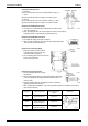
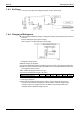
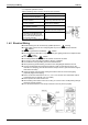
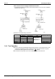
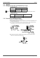
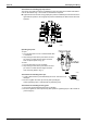
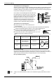
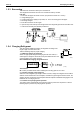
Table Of Contents
- Cover
- Table of Contents
- Packaged Air Conditioners Duct Connection Type (High static Pressure Application) FD-K Series — Cooling Only —
- Part 1 Model Name and Power Supply
- Part 2 Functions
- Part 3 Specifications
- Part 4 Remote Controller (Optional Accessories)
- Part 5 Field Piping and Wiring
- Part 6 Function and Operation
- Part 7 Troubleshooting
- 1. Maintenance Inspections
- 2. How to Handle Request for Maintenance
- 3. Troubleshooting Based on Equipment Condition
- 3.1 Troubleshooting Based on Equipment Condition
- 3.2 Equipment does not Operate
- 3.3 Fan Operates, but Compressor does not.
- 3.4 Cooling Operation Starts but Stops Immediately.
- 3.5 After Equipment Shuts Down, It cannot be Restarted for a While.
- 3.6 Equipment Operates but does not Provide Cooling.
- 3.7 Equipment Discharges White Mist
- 3.8 Equipment Produces Loud Noise or Shakes
- 3.9 Equipment Discharges Dust.
- Part 8 Removal Procedure
- Part 9 Appendix
- Packaged Air Conditioners Duct Connection Type (High static Pressure Application) FDY-K(A) Series — Heat Pump —
- Part 1 Model Name and Power Supply
- Part 2 Functions
- Part 3 Specifications
- Part 4 Remote Controller
- Part 5 Field Piping and Wiring
- Part 6 Field Setting
- Part 7 Function and Operation
- Part 8 Troubleshooting
- 1. Maintenance Inspections
- 2. How to Handle Request for Maintenance
- 3. Troubleshooting Based on Equipment Condition
- 3.1 Troubleshooting Based on Equipment Condition
- 3.2 Equipment does not Operate
- 3.3 Fan Operates, but Compressor does not.
- 3.4 Cooling/Heating Operation Starts but Stops Immediately.
- 3.5 After Equipment Shuts Down, It cannot be Restarted for a While.
- 3.6 Equipment Operates but does not Provide Cooling.
- 3.7 Equipment Operates but does not Provide Heating.
- 3.8 Equipment Discharges White Mist
- 3.9 Equipment Produces Loud Noise or Shakes
- 3.10 Equipment Discharges Dust.
- 3.11 Remote Controller LCD Displays "88".
- 4. Procedure of Self-Diagnosis by Remote Controller
- 5. Procedure of Self-Diagnosis by LED
- 6. Troubleshooting by Remote Controller Display / LED Display
- 6.1 Explanation for Symbols
- 6.2 Malfunction Code and LED Display Table
- 6.3 Failure of Indoor Unit PC Board
- 6.4 Malfunction of Heat Exchange Temperature Sensor System
- 6.5 Malfunction of Suction Air Temperature Sensor System
- 6.6 Malfunction of Remote Controller Air Thermistor
- 6.7 Actuation of Safety Device
- 6.8 Actuation of Safety Device
- 6.9 Failure of Outdoor Unit PC Board
- 6.10 High Pressure System (HPS) Malfunction
- 6.11 Low Pressure System (LPS) Malfunction
- 6.12 Malfunction of Electronic Expansion Valve
- 6.13 Discharge Pipe Temperature Malfunction
- 6.14 Malfunction of High Pressure Switch
- 6.15 Malfunction of Low Pressure Switch
- 6.16 Malfunction of Outdoor Temperature Sensor System
- 6.17 Malfunction of Discharge Pipe Temperature Sensor System
- 6.18 Malfunction of Heat Exchanger Temperature Sensor System
- 6.19 Short of Gas Malfunction
- 6.20 Reverse Phase
- 6.21 Malfunction of Transmission (Between Indoor and Outdoor Unit)
- 6.22 Malfunction of Transmission (Between Indoor Unit and Remote Controller)
- 6.23 Transmission Error Between Main Remote Controller and Sub Remote Controller
- 6.24 Failure of Field Setting Switch
- Part 9 Appendix
- Index
- Drawings & Flow Charts
Field Piping and Wiring Si42-107
42 Field Piping and Wiring
- ((6
:=60(6(
:66(0
#""
! 0(;;9 30
! (;606((666(
30
! 206
! /6604406066
! 5
! :60;6(;!F
! /6(660(
! :6600(!!6(
! 36(004600(6
! 566(6(66
((04666(466064
6(6(
! (606;4=066660
)606,0.
! <66D&D4D&DD&-D(:6(;
6D<D()>(.
! <9#6
! 3606640606
6==,6)φ-((.
! (66(66(;
006
6
0660
6
(;6
(
8=669,
0,
- (0;6
(
6=66(
0
'6(
6;#
N
69,
;,6(
$ 600
6!=0?
(P@460
6;
6(
N