
Service manual
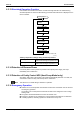
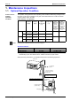
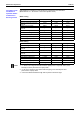
Table Of Contents
- Cover
- Table of Contents
- Packaged Air Conditioners Duct Connection Type (High static Pressure Application) FD-K Series — Cooling Only —
- Part 1 Model Name and Power Supply
- Part 2 Functions
- Part 3 Specifications
- Part 4 Remote Controller (Optional Accessories)
- Part 5 Field Piping and Wiring
- Part 6 Function and Operation
- Part 7 Troubleshooting
- 1. Maintenance Inspections
- 2. How to Handle Request for Maintenance
- 3. Troubleshooting Based on Equipment Condition
- 3.1 Troubleshooting Based on Equipment Condition
- 3.2 Equipment does not Operate
- 3.3 Fan Operates, but Compressor does not.
- 3.4 Cooling Operation Starts but Stops Immediately.
- 3.5 After Equipment Shuts Down, It cannot be Restarted for a While.
- 3.6 Equipment Operates but does not Provide Cooling.
- 3.7 Equipment Discharges White Mist
- 3.8 Equipment Produces Loud Noise or Shakes
- 3.9 Equipment Discharges Dust.
- Part 8 Removal Procedure
- Part 9 Appendix
- Packaged Air Conditioners Duct Connection Type (High static Pressure Application) FDY-K(A) Series — Heat Pump —
- Part 1 Model Name and Power Supply
- Part 2 Functions
- Part 3 Specifications
- Part 4 Remote Controller
- Part 5 Field Piping and Wiring
- Part 6 Field Setting
- Part 7 Function and Operation
- Part 8 Troubleshooting
- 1. Maintenance Inspections
- 2. How to Handle Request for Maintenance
- 3. Troubleshooting Based on Equipment Condition
- 3.1 Troubleshooting Based on Equipment Condition
- 3.2 Equipment does not Operate
- 3.3 Fan Operates, but Compressor does not.
- 3.4 Cooling/Heating Operation Starts but Stops Immediately.
- 3.5 After Equipment Shuts Down, It cannot be Restarted for a While.
- 3.6 Equipment Operates but does not Provide Cooling.
- 3.7 Equipment Operates but does not Provide Heating.
- 3.8 Equipment Discharges White Mist
- 3.9 Equipment Produces Loud Noise or Shakes
- 3.10 Equipment Discharges Dust.
- 3.11 Remote Controller LCD Displays "88".
- 4. Procedure of Self-Diagnosis by Remote Controller
- 5. Procedure of Self-Diagnosis by LED
- 6. Troubleshooting by Remote Controller Display / LED Display
- 6.1 Explanation for Symbols
- 6.2 Malfunction Code and LED Display Table
- 6.3 Failure of Indoor Unit PC Board
- 6.4 Malfunction of Heat Exchange Temperature Sensor System
- 6.5 Malfunction of Suction Air Temperature Sensor System
- 6.6 Malfunction of Remote Controller Air Thermistor
- 6.7 Actuation of Safety Device
- 6.8 Actuation of Safety Device
- 6.9 Failure of Outdoor Unit PC Board
- 6.10 High Pressure System (HPS) Malfunction
- 6.11 Low Pressure System (LPS) Malfunction
- 6.12 Malfunction of Electronic Expansion Valve
- 6.13 Discharge Pipe Temperature Malfunction
- 6.14 Malfunction of High Pressure Switch
- 6.15 Malfunction of Low Pressure Switch
- 6.16 Malfunction of Outdoor Temperature Sensor System
- 6.17 Malfunction of Discharge Pipe Temperature Sensor System
- 6.18 Malfunction of Heat Exchanger Temperature Sensor System
- 6.19 Short of Gas Malfunction
- 6.20 Reverse Phase
- 6.21 Malfunction of Transmission (Between Indoor and Outdoor Unit)
- 6.22 Malfunction of Transmission (Between Indoor Unit and Remote Controller)
- 6.23 Transmission Error Between Main Remote Controller and Sub Remote Controller
- 6.24 Failure of Field Setting Switch
- Part 9 Appendix
- Index
- Drawings & Flow Charts
Si42-107 Maintenance Inspections
Troubleshooting 207
+
&5"&
D
&5"
&
:6060;606
;6(06;;'>+A*
(6;
' N)O&
006=0?(P
! /0(466;=4
(;6GH6
36(0(46(60
"06
)8.
&
)8.
/60
:(
)L.
:(
)L.
5
J
/
2
:(
/60
:(
)L.
%5
J
/
2
:(
/60
:(
)L.
0 !"# $A1
)$A1.
!-1A!1
)!A$!.
$!A1 !A A +A
$!"# +A!
)+A!.
!-A!
)-A.
+!A ,A!
"0 !"# A $
)A1!.
!1A!
)-!A.
A1 ,A A-! A$
$!"# $A!
)$A!.
!1A!
)-!A.
$!A ,$A
5 %5
0% +L/2?1L32 -L/2
"0% !L/2 +L/2?$L32
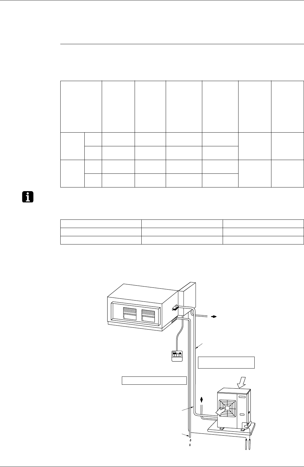
Transmission wiring
between indoor and
outdoor units
What about switch capacity?
What about cable thickness?
What about voltage and current?
Refrigerant piping
(Liquid + Gas)
Drain piping
Outdoor unit
Indoor unit
Earth
To dedicated
breaker
(P1668)
To dedicated
breaker