
Service manual
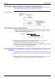
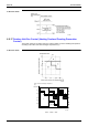
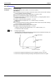
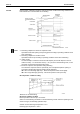
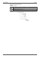
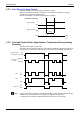
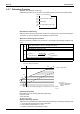
Table Of Contents
- Cover
- Table of Contents
- Packaged Air Conditioners Duct Connection Type (High static Pressure Application) FD-K Series — Cooling Only —
- Part 1 Model Name and Power Supply
- Part 2 Functions
- Part 3 Specifications
- Part 4 Remote Controller (Optional Accessories)
- Part 5 Field Piping and Wiring
- Part 6 Function and Operation
- Part 7 Troubleshooting
- 1. Maintenance Inspections
- 2. How to Handle Request for Maintenance
- 3. Troubleshooting Based on Equipment Condition
- 3.1 Troubleshooting Based on Equipment Condition
- 3.2 Equipment does not Operate
- 3.3 Fan Operates, but Compressor does not.
- 3.4 Cooling Operation Starts but Stops Immediately.
- 3.5 After Equipment Shuts Down, It cannot be Restarted for a While.
- 3.6 Equipment Operates but does not Provide Cooling.
- 3.7 Equipment Discharges White Mist
- 3.8 Equipment Produces Loud Noise or Shakes
- 3.9 Equipment Discharges Dust.
- Part 8 Removal Procedure
- Part 9 Appendix
- Packaged Air Conditioners Duct Connection Type (High static Pressure Application) FDY-K(A) Series — Heat Pump —
- Part 1 Model Name and Power Supply
- Part 2 Functions
- Part 3 Specifications
- Part 4 Remote Controller
- Part 5 Field Piping and Wiring
- Part 6 Field Setting
- Part 7 Function and Operation
- Part 8 Troubleshooting
- 1. Maintenance Inspections
- 2. How to Handle Request for Maintenance
- 3. Troubleshooting Based on Equipment Condition
- 3.1 Troubleshooting Based on Equipment Condition
- 3.2 Equipment does not Operate
- 3.3 Fan Operates, but Compressor does not.
- 3.4 Cooling/Heating Operation Starts but Stops Immediately.
- 3.5 After Equipment Shuts Down, It cannot be Restarted for a While.
- 3.6 Equipment Operates but does not Provide Cooling.
- 3.7 Equipment Operates but does not Provide Heating.
- 3.8 Equipment Discharges White Mist
- 3.9 Equipment Produces Loud Noise or Shakes
- 3.10 Equipment Discharges Dust.
- 3.11 Remote Controller LCD Displays "88".
- 4. Procedure of Self-Diagnosis by Remote Controller
- 5. Procedure of Self-Diagnosis by LED
- 6. Troubleshooting by Remote Controller Display / LED Display
- 6.1 Explanation for Symbols
- 6.2 Malfunction Code and LED Display Table
- 6.3 Failure of Indoor Unit PC Board
- 6.4 Malfunction of Heat Exchange Temperature Sensor System
- 6.5 Malfunction of Suction Air Temperature Sensor System
- 6.6 Malfunction of Remote Controller Air Thermistor
- 6.7 Actuation of Safety Device
- 6.8 Actuation of Safety Device
- 6.9 Failure of Outdoor Unit PC Board
- 6.10 High Pressure System (HPS) Malfunction
- 6.11 Low Pressure System (LPS) Malfunction
- 6.12 Malfunction of Electronic Expansion Valve
- 6.13 Discharge Pipe Temperature Malfunction
- 6.14 Malfunction of High Pressure Switch
- 6.15 Malfunction of Low Pressure Switch
- 6.16 Malfunction of Outdoor Temperature Sensor System
- 6.17 Malfunction of Discharge Pipe Temperature Sensor System
- 6.18 Malfunction of Heat Exchanger Temperature Sensor System
- 6.19 Short of Gas Malfunction
- 6.20 Reverse Phase
- 6.21 Malfunction of Transmission (Between Indoor and Outdoor Unit)
- 6.22 Malfunction of Transmission (Between Indoor Unit and Remote Controller)
- 6.23 Transmission Error Between Main Remote Controller and Sub Remote Controller
- 6.24 Failure of Field Setting Switch
- Part 9 Appendix
- Index
- Drawings & Flow Charts
Si42-107 Function Details
Function and Operation 199
/0 ,'
);66((.
0660)660(.J
6%8;:,
366(%<(660(60
!(46=06;(
698;@
66;()!(.46=66606
J
68,
66000J
(%<
,%
%
6,8#
3660600460J
!(660
"60(:
'
≥ !L
- %")%<
→
%.
Z
%'
Z
06(6-6
)Y;66;6006.
:6(%<(6!
:6(%<(
%'
%6606((
%6606((
%")".%<
Startup or end of defrosting
Check of defrosting start conditions
Defrosting operation
Control for delayed ON of outdoor fan
(P1345)
(A)
(B)
(C)
(D)
&
(
Te≤0˚C
Te≤0.4Ta-10˚C
&
(
Te≤0˚C
Te≤0.4Ta-6˚C
changing SW
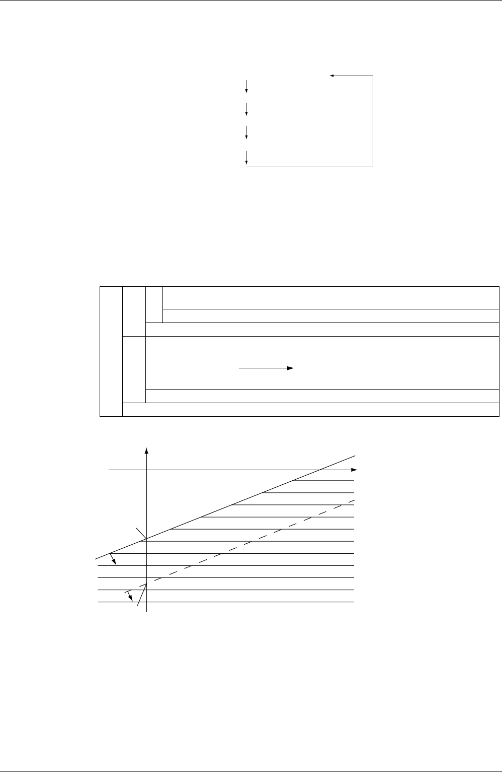
–6˚C
15˚C
T
A (outdoor temperature)
Area shaned with horizontal lines at left: Defrostion can be started.
–10˚C
(P1346)
α =6
α =10
TR (heat exchanger temperature)
Te = 0.4×T
A - α
α=6(Can be switched to α =
10 by changing slide
switch.)