Si42-107 Service Manual Packaged Air Conditioners Duct Connection Type (High Static Pressure Application) FD(Y)-K(A) Series [Applied Models] Cooling Only Heat Pump
Si42-107 Packaged Air Conditioners Duct Connection Type (High Static Pressure Application) FD(Y)-K Series Packaged Air Conditioners Duct Connection Type (High static Pressure Application FD-K Series — Cooling Only — ...................... 1 Part 1 Model Name and Power Supply ...................
Si42-107 $ /!-*4 ! *4 ! * /!$*4 ! *4 !* 1 / *4 !* - '+ 54 !! 54 5 -1 '5!$*
Si42-107 Packaged Air Conditioners Duct Connection Type (High static Pressure Application) FDY-K(A) Series — Heat Pump —.............. 107 Part 1 Model Name and Power Supply .....................................
Si42-107 - ( 0 % $ - - 8 8 0 $ Part 7 Function and Operation .................................................
Si42-107 $ $ $ $ $ $ + $ $ 1 $ ! $ $ $ $ $ $ $ $ + $ $ 1 $ ! $ $ 5 2 - 8 " 6 0 : ( ( -$ 8 : ( ( -+ 8 ' ( :6 ( /
Si42-107 vi Table of Contents
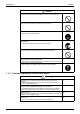
Si42-107 Introduction ! 2 6 0 ; 0 = ! :6 ( G H G H :6 G H ( ( 6 6 I 6 :6 G H ( ( 6 :6 4 ; ; 6
Introduction Si42-107 / 6 ( 6 6 3 = 0 6 9 ( 6 6 6 = / 6 ; 6 0 3 6 0 6 6 6 = 2 6 0 0 6 0 6 9 ( 6 ( 4 6 = 2 6 6 0 6 ; 6 0 6 9 ( :6 6 06
Si42-107 Introduction 2 6 9 ( 4 6 6 6 9 ( 4 6 0 0 6 ( 6 0 = ( = 6 = 2 6 ; ; 6 8 = 6 6 ; 6
Introduction Si42-107 / I ; ; 4 6 6 ( 6 6 4 6 =4 6 0 6 = 6 ( 4 6 6 ( ( ( 6 0 4 6 = 6 (
Si42-107 Packaged Air Conditioners Duct Connection Type (High static Pressure Application) FD-K Series — Cooling Only — Model Series Class Indoor Units 3HP 4HP FD03K FD04K 5HP 6HP 8HP 10HP FD05K FD06K FD08K FD10K 15HP 20HP FD15K FD20K Outdoor Units R71FU R100FU R125FU RU06K RU08K RU10K RU08K×2 RU10K×2 1
Si42-107 2
Si42-107 Part 1 Model Name and Power Supply Model Name and Power Supply 3
Power Supply Si42-107 ! " " ! (; > 4 /!-*> % '+ 5> -φ - !A F !"# ) .
Si42-107 External Appearance #$ " % #$ " % & Model Name and Power Supply 5
External Appearance 6 Si42-107 Model Name and Power Supply
Si42-107 Part 2 Functions Functions 7
Function Si42-107 ' ' ( % ' ; % 8 I ; 6 0 & 0 6 ; "J 0 8 , ( 6 6 0 / " 06 : /,* " ") 6 0 8 . ( " ") * .
Si42-107 Part 3 Specifications Specifications ! !"# ! $!"# 9
Specifications Si42-107 ()* & + " ! 0 5 0 % 5 &9 @ / &9 @ / =3 2 ?6 = ?6 M (( (( (( (( (( (( : ' K 0 K 6 : / ' / ( 3 06 & 8 % "K3K/ ',( -. 0 ' . +4 !! +4!!! !!,! φ1 )2 # 0. φ 1 )2 # 0. -? 2 φ1 ) . φ 1 ) .
Si42-107 Specifications & ', (-. ', -. ', (-. (-. (1-. 2 (-. 2 =3 1 + $ 1 ! 0 2 ?6 ! 4 !! $$4!!! ! 4 !! = ?6 4 !! 4 !! 4!!! M !!,! !!, !,! !!, !,! Kφ + )2 # 0. Kφ 1 )2 # 0. φ 1 )2 # 0. &9 (( Kφ )2 # 0. Kφ- )2 # 0. @ (( φ- )2 # 0. 5 / (( -? 2 2 2 0 Kφ + )2 # 0. Kφ 1 )2 # 0. φ 1 )2 # 0. &9 (( % @ Kφ )2 # 0.
Specifications Si42-107 /()* & + " ! 0 5 0 % 5 &9 @ / &9 @ / =3 2 ?6 = ?6 M (( (( (( (( (( (( : ' K 0 K 6 : / ' / ( 3 06 & 8 % "K3K/ ',( -3% 0 ' 3% $ 14 !! +4 !! !!,! φ1 )2 # 0. φ 1 )2 # 0. -? 2 φ1 ) . φ 1 ) . φ $ ! )" .
Si42-107 Specifications & ', (-4% ', -4% ', (-4% (-4% (1-4% 2 (-4% 2 =3 1 + $ 1 ! 0 2 ?6 ! 4 !! $$4!!! ! 4 !! = ?6 4 !! 4 !! 4!!! M !!,! !!, !,! !!, !,! Kφ + )2 # 0. Kφ 1 )2 # 0. φ 1 )2 # 0. &9 (( Kφ )2 # 0. Kφ- )2 # 0. @ (( φ- )2 # 0. 5 / (( -? 2 2 2 0 Kφ + )2 # 0. Kφ 1 )2 # 0. φ 1 )2 # 0.
Specifications 14 Si42-107 Specifications
Si42-107 Part 4 Remote Controller (Optional Accessories) % $ % & $ ' ( )*' +,-. + / 0 ' ( )*' +, . 1 ' ( )*' +, 2.
Optional accessories Si42-107 & " & % ' ( ' ( = 8 6 : / 0 : - 8 : ( * 16 3 6 - 8 : ( 3 : ; 8 /!-*4 ! * > 4 F & /! *4 !$*4 ! *4 !* / *4 !* > 4 : & > 4 : & *' +,- *' +,<%: . *' +, 2 <%: . *' +, *' +, <%: .
Si42-107 Optional accessories 5 "" 6- 07 8 *' +,- 6 0 4 6 = 5 "" ) " Remote Controller (Optional Accessories) 17
Optional accessories Si42-107 " 9 69 $8 150 80 15 220 4-Ø6HOLE 200 60 240 (P1392) :" :" " ; 5 615 5 ! "" : < " :" = 8 :" : ! # $ 18 Remote Controller (Optional Accessories)
Si42-107 Optional accessories , " 5 "" 6- 07 8 , " 5 "" %>& ! "" : ; 5 6 8 Remote Controller (Optional Accessories) 19
Optional accessories Si42-107 5 "" 6- 07 98 , " 5 "" - 07 9 20 Remote Controller (Optional Accessories)
Si42-107 Optional accessories " , 5 - 07 B C D A E ~ ~ ~ ~ B C A D ~ ~ ~ ~ B C A 3 THERMOSTAT FAN P1 FD06-10 FD03-05 N L (ON/OFF) P3 FD15-20 P5 ON ELECTRONIC CONTROL TEMPERATURE CONTROL OFF P6 (P1256) - 07 ROOM SENSOR P21 B P1 FD15•20 P1 P2 P2 A E D FD06~10 P1 P3 P6 C A P2 P6 P7 P3 P3 A C P10 P11 B D P6 C P10 P11 B P8 P10 P11 P12 P13 P14 P15 P16 P17 P18 DISPLAY 3 FD03~05 (P1257) Remote Controller (Opt
Optional accessories Si42-107 - 07 9 A A D B B J C ON OFF COOL D E HEAT F C G H FD15•20 I H E-F E-G E-H E-I L H TEMPERATURE 22 (P1258) Remote Controller (Optional Accessories)
Si42-107 Part 5 Field Piping and Wiring 0 3 0 $ Field Piping and Wiring /!-*4 ! *4 ! * /!$*4 ! *4 !* 1 / *4 !* - '+ 54 !!
Field Piping and Wiring Si42-107 ' " ',( -? ( -? ( - "" 6 6 0 ; = 6 ; ) 0 . 5 0 6 4 06 ; 6 6 6 ; I 6 6 6 06 - 8 = 6 6 ) 0 $.
Si42-107 Field Piping and Wiring , ; ; " : ; " 5 : ; " ? ; ! ! ' ( 6 ; 6 6 0) . ; 6 0 6 ( 6 0) . ) 0 +. ! ; # 0 6 6 0 4 6 0 6 6 ) 0 1 !.
Field Piping and Wiring Si42-107 , @ 4; 5 : "" ; ! ; 5 : " ! < ! 5 : " @ ! (; 6 6 0 ! :6 ; 6 6 06 :6 0 ; ( 6 6 06 ! ; 4 = 6 0 6 ; 6 0 0 ( ) 6
Si42-107 Field Piping and Wiring ' 6 ( 6 6 ( ) . 6 0 0 ( 6 ! 6 6 6 06 6 0 6 ; ( 6 6 ; ) 0 -.
Field Piping and Wiring Si42-107 , "" ; ! ; : $ ; " ; " 6; $ ; 8? ; < " " ; @ : " @ ! 6 0 6 6 ; ! ( 6 6 0 6 6 6 ( ) 0 .
Si42-107 Field Piping and Wiring ',(/-? (1-? (- "" 6 6 0 ; = 6 ; ) 0 . 5 0 6 4 06 ; 6 6 6 ; I 6 6 6 06 - 8 = 6 6 ) 0 $.
Field Piping and Wiring Si42-107 @ A' ? ; "" 5 "B , 5 $ ; ; ; ; " 3 " ; ; " " @ "" ! 0 6 ; ; # 6 6 = 6 # 6 0 0 6 6 6 ; ! 5 ( 0 ' 0 0 # /!$ @ φ 1 K !4 &S ! φ1 K ! 4 &S
Si42-107 Field Piping and Wiring , @ 4; 5 : "" ; ! ; 5 : " ! < ! 5 : " @ ! (; 6 6 0 ! :6 ; 6 6 06 :6 0 ; ( 6 6 06 ! ; 4 = 6 0 6 ; 6 0 0 ( ) 6
Field Piping and Wiring Si42-107 A+ ; ! 5 "" B % 6 6 ; ; ( 0 6 ) 0 .
Si42-107 Field Piping and Wiring (( ; ( ; ( ; 6 6 6 6 0 0 ( 6 ( ! 5 "" 3 5 ( 5& ! 3@ 9 # )((P. ! + 6 9 75 " 5 ; 5 ? ; ! ; 5 5 ! 6 6 ; ; ) 0 .
Field Piping and Wiring Si42-107 ', -? (- "" - ' ' 6 0 ) (( ; . 6 8 6 0 6 ; ) 0 $. 5 0 6 4 06 ; 6 6 6 ; I 6 6 6 06 8 = 6 6 ) 0 +.
Si42-107 Field Piping and Wiring @ A' ? ; "" 5 " B , 5 $ ; ; ; ; " 3 " ; ; " " @ "" ! 0 6 ; ; # 6 6 = 6 # 6 0 0 6 6 6 ; ! 5 ( 0 ' 0 0 # / @ )φ K 4 &S .
Field Piping and Wiring Si42-107 , @ 4; 5 : "" ; ! ; 5 : " ! < ! 5 : " @ ! (; 6 6 0 ! :6 ; 6 6 06 :6 0 ; ( 6 6 06 ! ; 4 = 6 0 6 ; 6 0 0 ( ) 6
Si42-107 Field Piping and Wiring ! 6 6 6 06 6 0 6 ; ( 6 6 ; ) 0 - .
Field Piping and Wiring Si42-107 9 75 " 5 !; ; 5 ? ; ! ; 5 5 ! 6 6 ; ; ) 0 .
Si42-107 Field Piping and Wiring 0 ' ? ((' ? ' * 5 :" ; ( 6 0 0 # ) . ' 0 0 # % ' 0 0 # + @ φ 1K ! !!C φ 1 K ! & 9 φ1 K ! );.
Field Piping and Wiring Si42-107 A& 3 "< B % 0 ) . : 6 ( ? = 4 0 )U. );. 6 6 6 6 :6 0 ) . : 6 ( ? = 4 0 )U. );.
Si42-107 Field Piping and Wiring % 0 6 0 (4 0 ( ( ; ! :6 9 6 0 0 0 0 6 0 6 6 : = 6 0 6 0 0 ' 0 0 , 0 6 ' 0 6 0 ( 6 0 0 0 ) .
Field Piping and Wiring Si42-107 - ( ( 6 : = 6 0 ( 6 ( 0 0 6 0 6 6 0 6 6 ( ; 6 ( - ( 0 ; 6 ( 8 = 6 6 9 , 0 , 6 = 6 6 ( 0 ' 6
Si42-107 Field Piping and Wiring A) ! ; ! " : ! B 6 0 6 0 ; 4 6 8 6 0 ( 8 '+ 5> 3 )!. "! FF,5 @ ' !! 5> ' 5> "! FF,5 @ "! FF,5 @ '+ 5F ' !! 5F -! -! "! FF,5-@ "! FF,5-@ ! 4 3 0 ; 6 )!.
Field Piping and Wiring Si42-107 (/- * %"" ! :" ; * % '5!$*> '5!$*: & & 9 φ 1 K ! φ 1 K ! ! 5 6 ( ; 0 3 06 )6 0 ( ( ( 11 M. J % --$ %"" ! :" " ; , ' 0 # @ 8 ( ( ; 0 0 6 ) 6 # 0 9 0 6.
Si42-107 Field Piping and Wiring A ; " < "< B :6 ( 6 6 0 6 6 ; 0 :6 ; 6 ( ! : 06 6 ; 0 0 6 ; 6 ; = 6 0 6 / 0 6 ; 6 6 6 (P1456) & < "< : J : 6 ( ?
Field Piping and Wiring Si42-107 A B 6 ( 0 0 6 6 ( 6 ( I 6 6 06 6 ( 9 6 6 6 ; 0 0 6 6 ( ( = 6 6 0 0 6 6 ( 0 ; 6 ( 6 6 06 6 6 4 6 ( (
Si42-107 #< Field Piping and Wiring :6 6 = = ; 6 ( :6 0 ; 6 = = ; 6 @ 6 6 = ( )< ( .
Field Piping and Wiring Si42-107 < ; 7 ; " !7 ! ; ; ( 0 ; 6 ( ( 6 ; 6 6 9 0 6 = 6 6 ( 0 ( N ; # - 6 9 , 0 6 ( ; 0 6 ( 36 6
Si42-107 Field Piping and Wiring 5 (P1469) 8 3 )!. '5!$*> "! FF,5 @ '5!$*: & "! FF,5 @ # 3 0 ; 6 )!. 3 0 # ( ( 6 6 ; "! FF,5 @ ! "! FF,5 @ ! ! % 4 "!+'<, 6 6.
Field Piping and Wiring / Si42-107 (1-? (- / @ ! :6 0 ( 6 0 ' 0 0 J ( 0 6 6 0 6 6 # # J 0 ; 8 ' 0 0 # @ %/ K : )8 . & 9 %/ K : )8 .
Si42-107 Field Piping and Wiring / % ; ! ; 4; 5 " ; ! ; ; %"! ; ; ! ; ' " ! "" 5 ; 5 , ; ; 5 ! ; !; " ! ( 0 6 ( 6 ( ( ! :6 6 ; 6 = = ; 6 ( ! ' 0 0 ( ; 6 = = ; 6
Field Piping and Wiring Si42-107 / #" @ ! 0 ( 6 6 ; ; ( ( 6 ; 6 0 6 6 6 ; 0 ! % ! ' 6 G3 0 / 0 (H 6 6 0 ! = ( ; ( ; ! :6 6 ( 0 ( 6 0 6 0 6 (
Si42-107 Field Piping and Wiring ! 6 6 0 ; 4 6 0 ; ( 6 4 06 6 6.
Field Piping and Wiring 54 Si42-107 Field Piping and Wiring
Si42-107 Part 6 Function and Operation % $ 5 $ % 5 + % 6 % 6 ) /,*7', 5.
Function Outline Si42-107 ' & " ',7- (Input) Indoor Unit (Output) Thermostat Control Remote Controller with Liquid Crystal Fan Motor Fan Operation ON/OFF Fan Operation Cooling Operation Malfunction Detection Function ∗ Fan Motor over Current Thermostat 3 Minutes Timer 56 (P1259) Funciton and Operation
Si42-107 Function Outline & + " (Output) (Input) Outdoor Unit Discharge Pipe Thermostat Switch Compressor ON/OFF Control Compressor Fan Motor Thermostat Switch Malfunction Detection Function Outdoor Fan Motor Compressor over Current Switch RU Model Only High Pressure Switch RU Model Only Low Pressure Switch RU06K Only Functon and Operation (P1260) 57
Operation Flow Chart Si42-107 & '" ! ; & '" ! ; 6',7-C 7' 8 V W Power switch on remote controller ON. Is F1C of indoor unit in normal condition. Unit does not NO operate. YES Relay K1R of indoor unit is ON Press Fan operation button. Mgs K1M of indoor unit is ON. Indoor unit Fan operates. Press cooling button. Thermostat ON judgement. Thermostat OFF Thermostat ON Mgs K1M of outdoor unit is ON, then compressor and outdoor fans operates.
Si42-107 Operation Flow Chart V W Power switch on remote controller ON. Is F1C of indoor unit in normal condition. Unit does not NO operate. YES Relay K1R of indoor unit is ON Press Fan operation button. Mgs K1M of indoor unit is ON. Indoor unit Fan operates. Press cooling button. Thermostat ON judgement. Thermostat OFF Thermostat ON Mgs K1M of outdoor unit is ON, then compressor and outdoor fans operates. F1C of indoor unit actuates.
Operation Flow Chart Si42-107 & '" ! ; 6',7-C 7-8 ∗ :6 /!$A !*7'5!$A !* / *? / !* ; 6 ( V W Power switch ON. Is safty device in normal condition. Unit does not NO operate. YES Relay K1R of outdoor unit is ON. Relay K2R, K3R of indoor unit are ON. Press Fan operation button. Mgs K2M of indoor unit is ON, and relay K2R, K4R are ON. Indoor Fan operates. Press cooling button.
Si42-107 Operation Flow Chart V W Power switch ON. Is safty device in normal condition. Unit does not NO operate. YES Relay K1R of outdoor unit is ON. Relay K2R, K3R of indoor unit are ON. Press Fan operation button. Mgs K2M of indoor unit is ON, and relay K2R, K4R are ON. Indoor Fan operates. Press cooling button. Thermostat ON judgement. Thermostat OFF Thermostat ON Mgs K1M of outdoor unit is ON, then compressor and outdoor fans operates. F2C of indoor unit actuates.
Electric Function Parts Si42-107 #" ' ',7-. ' ( !- 8 8 8 0 6 ! *' +,-4 *' +, )/ 0 : . : %,* -φ - !? F ! =3 &* B:" !, $ !F : %,* -φ - !? F ! + =3 &* B:" !, $ !F 8 % ' ' ( 8 8 8 0 6 8 % ' ! !$ ! ! *' +,-4 *' +, )/ 0 : .
Si42-107 Electric Function Parts ',7-. ' ( 8 8 8 0 6 8 % ' ! *' +,- ) :6 ( .4 *' +, )/ 0 : . *' +, 2 ) :6 ( . 7 *: 1 ∗ : % : % -φ - !? F !"# =3 -φ - !? F !"# - + =3 &*, B: !, $ !F ! &*, B: !, $ !F ! ∗ *: 1 J - ( 0 ( ',7-4% ' ( 8 8 8 0 6 ! *' +,- ) :6 ( .
Electric Function Parts Si42-107 & >' 8 ( * 8 8 8 0 6 % 5 )5 . 8 % 5 )& . % 5 8 :6 ( R & R & ' ' 2 * -' '4 ' % 5 )5 . % 5 )& .
Si42-107 Electric Function Parts 7-. 8 ( * 8 8 0 6 8 % ' 8 )5 . 8 8 )& .
Electric Function Parts 66 Si42-107 Funciton and Operation
Si42-107 Part 7 Troubleshooting 8 $ % $ " " ' 9 8 +! 6 +! - : ; 6 0 2 9 (
Maintenance Inspections Si42-107 + &< < ! D & 5 " & :6 0 6 0 ; 6 0 6 ; 6 ( 0 6 ; ; '+ , 5 ( 6 ; J G"H 0 " 06 )8 . & )8 . ! $ A 1 "# ) $ A 1 . $! + A "# ) + A ! .
Si42-107 " % 7 E & F Maintenance Inspections 36 6 ( ( (( # 6 ; ; )8 ( , ! ( ( . )36 0.
How to Handle Request for Maintenance Si42-107 ) ! ) " = + '" ! ; 6 ( 6 ( (1) The operation circuit fuse is disconnected or is making poor contact. (2) The operation swich is broken or its contact is defective. (3) The high pressure switch is broken. (4) The fan motor's magnetic switch is broken. (5) The fan motor's protection thermostat is being actuated or is broken. (6) The compressor's overcurrent relay is broken.
Si42-107 Troubleshooting Based on Equipment Condition 4 :" ; 9 #= 5 4 :" ; 9 #= 5 ' ( 0 + - 4 ; ( 0 ; (( 0 + 0 + 9 ( 6 4 ; 6 9 ( ; 0 0 + Troubleshooting 9 ( 9 ( $ + 9 ( 6 0 6
Troubleshooting Based on Equipment Condition % " Si42-107 #= 5 & :" + " :" /,* ! ! ! ! ! ! ! ! ! ! ; 6 ( 6 06 6 ( 0 6 ( 6 ( ( ( ( 6 (
Si42-107 % " Troubleshooting Based on Equipment Condition ' & ? : 5 :" + " :" /,* ! ( ! ( 0 6 ( 4 :" ; Caution Be sure to turn off power switch before connect or disconnect connector, or parts damage may be occurred. Make the following temperature setting using remote controller. Cooling: Lowest setting YES Does equipment operate? YES Normal.
Troubleshooting Based on Equipment Condition % " Si42-107 " & : 55 " :" + " :" /,* ! ! ! ! ! ! ! ! 6 0 0 0 ( 6 ( 0 6 ( ( 6 6 0 :6 0 ( 8 4 :" ; Caution Be sure
Si42-107 % " Troubleshooting Based on Equipment Condition % #= 5 ; , ! ? ; " :" + " :" : /,* ! % ) ( .
Troubleshooting Based on Equipment Condition / % " Si42-107 #= 5 & : < " :" + " :" /,* ! % ) ( .
Si42-107 0 % " Troubleshooting Based on Equipment Condition #= 5 , ; ; + :" + " :" /,* ! ! ! ! ! " ( 6 ( 6 6 0 00 8 ( 4 :" ; Caution Be sure to turn off power switch before connect or disconnect connector, or parts damage may be occurred.
Troubleshooting Based on Equipment Condition 1 % " #= 5 :" + " :" Si42-107 ; @ /,* ! 6 0 0 ! 0 ( ! 6 0 0 6 0 ) 6 . 4 :" ; Caution Be sure to turn off power switch before connect or disconnect connector, or parts damage may be occurred.
Si42-107 G % " Troubleshooting Based on Equipment Condition #= 5 , ; , :" + " :" /,* ! ( ! ( T 6 4 :" ; Caution Be sure to turn off power switch before connect or disconnect connector, or parts damage may be occurred. Does the trouble generate at the time of operation start again after extended period of operation? YES Dust collected inside the indoor unit are blown out. Cleaning for inside of indoor unit is necessary.
Troubleshooting Based on Equipment Condition 80 Si42-107 Troubleshooting
Si42-107 Part 8 Removal Procedure '+ 5> Removal Procedure ' ( ' ( ' ( ' ( 0 % 5 8 2 (
For R71FUY1 Si42-107 ' 0 ' .
Si42-107 For R71FUY1 5 < " & ' ' + 9 "" ! " : 5:" ! @ ! ' ( 6 0 4 4 0 6 ( 0 6 0 ' ( 6 6 ; 0 6 6 0 0 6 ?; ( ? 06 4 ( 6 6 0 0 - ' ( 6 ; 0
For R71FUY1 5 < " #" - 84 " 9 $ 9 "" ! " : 5:" ! @ ! ' ( 6 4 0 0 0 6 ( 0 ' ( 6 ( 6 6 0 ) ( 04 6 .
Si42-107 For R71FUY1 5 < " 5 9 "" ! " : 5:" ! @ ! ' ( 6 04 4 0 ( ' ( 6 ( 0 / 6 ( ( 6 ( ( - " 6 ; # 6 6 0 4 ( ( 6 0 6 4 Removal Procedure 85
For R71FUY1 86 Si42-107 ' ( 6 ( E 6 ; 5 :, ; & 6 ( 06 Removal Procedure
Si42-107 Part 9 Appendix 0 / 0 ( 0 % 3 0 / 0 ( 1! !"# 1! $!"#
Piping Diagrams Si42-107 , 5 " & " ',( -C 0 ' F ',( -C ((' F ',( -C ' ',(/-C (/- 88 Appendix
Si42-107 Piping Diagrams ',(1-C (1- F ', (-C (- ', -C (1-2 F ', (-C (-2 Appendix 89
Wiring Diagram Si42-107 , 5 ()* ',( H( H( -.
Si42-107 Wiring Diagram 0 ' . 3D000995C ((' . F ' .
Wiring Diagram Si42-107 ',(/-. C (/-.
Si42-107 Wiring Diagram ',(1-. C (1-. F ', (-. C (-.
Wiring Diagram Si42-107 ', -. C (1-. 2 F ', (-. C (-.
Si42-107 Wiring Diagram ',( > (-.
Wiring Diagram Si42-107 ', H (-.
Si42-107 Wiring Diagram /()* ',( H( -3% Appendix 97
Wiring Diagram Si42-107 0 ' 3% 3D005375C ((' 3% 3D005376C 98 Appendix
Si42-107 Wiring Diagram ',( -4% Appendix 99
Wiring Diagram Si42-107 ' 4% 100 Appendix
Si42-107 Wiring Diagram ',(/-4% C (/-4% Appendix 101
Wiring Diagram Si42-107 ',(1-4% C (1-4% F ', (-4% C (-4% 102 Appendix
Si42-107 Wiring Diagram ', -4% C (1-4% 2 F ', (-4% C (-4% 2 Appendix 103
Wiring Diagram Si42-107 ',( ? ( -3% F ',( > (-4% 104 Appendix
Si42-107 Wiring Diagram ', H (-4% Appendix 105
Wiring Diagram Si42-107 106 Appendix
Si42-107 Packaged Air Conditioners Duct Connection Type (High static Pressure Application) FDY-K(A) Series — Heat Pump — Model Series Class Indoor Units Outdoor Units 6HP 8HP 10HP 15HP 20HP FDY06K(A) FDY08K(A) FDY10K(A) FDY15K(A) FDY20K(A) RY140KU RY200KU RY250KU RY200KU×2 RY250KU×2 107
Si42-107 108
Si42-107 Part 1 Model Name and Power Supply 8 < ( ! " 06 : ! Model Name and Power Supply 109
Model Series and Nomenclature Si42-107 + " 5 " ) ; 4 + " ! 5: " !"# " ! > " -φ4 - !A F4 !"# ) 8 - . )% 5 . : & -φ4 !F4 $!"# $!"# > & -φ4 - !F4 $!"# ) 8 - . )% 5 . & />!$*) .> '> !*5> />! *) .> '> !!*5> /> !*) .> '> !*5> /> *) .> '> !!*5> K /> !*) .
Si42-107 External Appearance #$ " % #$ " % />!$*) . />! *) . /> *) . /> !*) . /> !*) . 5 "" 3 : 2' 2$ 3 : 2' $ 3 : 2' $ 0 ' 0 5 ) : .
External Appearance 112 Si42-107 Model Name and Power Supply
Si42-107 Part 2 Functions Functions 113
Functions Si42-107 ' ' % 8 / " 06 : />,* " & / 3 ' ( " " " : ( ( ? " 6 0 % " " 6 0 % / 0 6 0 & 0 6 , ( 6 6 0 2 = : ( = ; ' ( < />!$4! 4 !* % " " 8 6 0 -!( ( />!$* />! A !* " " "
Si42-107 Part 3 Specifications Specifications $ * !"# $ * $!"# * !"# ! * $!"#
Specifications Si42-107 - ()* + " ',.(/-. ',.(1-. ',. (-. . (- . . ((- . . (- . ? ? 14 !!? 4 !!? 4 !! 4 !!? 4 !!? 4 !! -? -? 4 !!? 4 !!? 4 !! -4 !!? -4 !!? -4 !! ? ? +$4 !!?+ 4+!!?+ 4+!! 14-!!? 14 !!? 14 !! - ? - ? - + 4 !!?+14 !!?+ 4 !! 141!!? !4!!!? 141!! + $? + ? + 1 4 !!?1 4 !!?1 4 !! -4+!!? -4-!!? -4-!! 1 ? 1 ? 1 !!4-!!? !!4+!!? !!4-!! 4-!!? 4 !!? 4-!! ',.(/-. ',.(1-.
Si42-107 Specifications + " & ! 4 ! 0 ) .?) .?)-. ! 4 !- " 0 ) .?) .?)-. =3 2 ?6 = ?6 =3 2 ?6 = ?6 ',. -. ',. (-. . ((- . 2 . (- . 2 !? - ? - !4!!!? 4!!!? 4!!! -+4 !!?-+4 !!?-+4 !! $? ? $ 4!!!? -4!!!? 4!!! - 4 !!?- 4 !!?- 4 !! - 1? - !? - ! 4!!!? 4!!!? 4!!! $4 !!? 4$!!? 4$!! $ $? $ ? $ $ 1-4!!!? 1 4!!!? 1-4!!! 4+!!? 4 !!? 4+!! ',. -.
Specifications Si42-107 - /()* + " ! 4 !- " 0 ) .?) .?)-. . ((- 4% . (- 4% . ((- .% . (- .% =3 2 ?6 = ?6 =3 2 ?6 = ?6 ? ? +$4 !!?+ 4+!!?+ 4+!! 14-!!? 14 !!? 14 !! - ? - ? - + 4 !!?+14 !!?+ 4 !! 141!!? !4!!!? 141!! + $? + ? + 1 4 !!?1 4 !!?1 4 !! -4+!!? -4-!!? -4-!! 1 ? 1 ? 1 !!4-!!? !!4+!!? !!4-!! 4-!!? 4 !!? 4-!! / ( ',. (-4% ',. (-.% 4% . ((- 4% . (- 4% . ((- .% . (- .
Si42-107 Specifications + " ! 4 !- " 0 ) .?) .?)-. . ((- 4% 2 . (- 4% 2 . ((- .% 2 . (- .% 2 =3 2 ?6 = ?6 =3 2 ?6 = ?6 !? - ?- + !4!!!? 4!!!? - 4!!! -+4 !!?-+4 !!?--4-!! $? ? $ 4!!!? -4!!!? 4!!! - 4 !!?- 4 !!?- 4 !! - 1? - !? + 4!!!? 4!!!? $ 4!!! $4 !!? 4$!!? !4+!! $ $? $ ? $ $ 1-4!!!? 1 4!!!? 1-4!!! 4+!!? 4 !!? 4+!! / ( ',. -4% ',. (-4% ',. -.% ',. (-.% =3 (Q?( 2 ) .
Specifications Si42-107 -% ()* + " ',.(/-%. ',.(1-%. & . (- . . ((- . . (- . ? ? 14 !!? 4 !!? 4 !! 4 !!? 4 !!? 4 !! -? -? 4 !!? 4 !!? 4 !! -4 !!? -4 !!? -4 !! ? ? +$4 !!?+ 4+!!?+ 4+!! 14-!!? 14 !!? 14 !! - ? - ? - + 4 !!?+14 !!?+ 4 !! 141!!? !4!!!? 141!! + $? + ? + 1 4 !!?1 4 !!?1 4 !! -4+!!? -4-!!? -4-!! 1 ? 1 ? 1 !!4-!!? !!4+!!? !!4-!! 4-!!? 4 !!? 4-!! ',.(/-%. ',.(1-%. ',.
Si42-107 Specifications + " & ! 4 ! 0 ) .?) .?)-. ! 4 !- " 0 ) .?) .?)-. =3 2 ?6 = ?6 =3 2 ?6 = ?6 ',. -%. ',. (-%. . ((- . 2 . (- . 2 !? - ? - !4!!!? 4!!!? 4!!! -+4 !!?-+4 !!?-+4 !! $? ? $ 4!!!? -4!!!? 4!!! - 4 !!?- 4 !!?- 4 !! - 1? - !? - ! 4!!!? 4!!!? 4!!! $4 !!? 4$!!? 4$!! $ $? $ ? $ $ 1-4!!!? 1 4!!!? 1-4!!! 4+!!? 4 !!? 4+!! ',. -%.
Specifications Si42-107 -% /()* + " ! 4 !- " 0 ) .?) .?)-. . ((- 4% . (- 4% . ((- .% . (- .% =3 2 ?6 = ?6 =3 2 ?6 = ?6 ? ? 1 +$4 !!?+ 4+!!?$+4$!! 14-!!? 14 !!? +4!!! - ? - ? 1 + 4 !!?+14 !!?+ 4 !! 141!!? !4!!!? 14+!! + $? + ? 1 4 !!?1 4 !!? 41!! -4+!!? -4-!!? !41!! 1 ? 1 ? 1 !!4-!!? !!4+!!?114-!! 4-!!? 4 !!? 4!!! / ( ',. (-%4% ',. (-%.% 4% . ((- 4% . (- 4% . ((- .% . (- .
Si42-107 Specifications + " ! 4 !- " 0 ) .?) .?)-. . ((- 4% 2 . (- 4% 2 . ((- .% 2 . (- .% 2 =3 2 ?6 = ?6 =3 2 ?6 = ?6 !? - ?- + !4!!!? 4!!!? - 4!!! -+4 !!?-+4 !!?--4-!! $? ? $ 4!!!? -4!!!? 4!!! - 4 !!?- 4 !!?- 4 !! - 1? - !? + 4!!!? 4!!!? $ 4!!! $4 !!? 4$!!? !4+!! $ $? $ ? $ $ 1-4!!!? 1 4!!!? 1-4!!! 4+!!? 4 !!? 4+!! / ( ',. -%4% ',. (-%4% ',. -%.% ',. (-%.
Specifications 124 Si42-107 Specifications
Si42-107 Part 4 Remote Controller ' ( $ 3 ' ( 2' $ 3 ' ( 2' $ + - 3 ' ( 2' $ Remote Controller 125
Remote Controller Si42-107 5 "" 126 5 "" 9 Remote Controller
Si42-107 Remote Controller 5 "" 9 / 5 4 7 6 10 2 1 3 A 8 9 11 hr hr NOT AVAILABLE TEST 18 12 13 TEST 14 Fig.1 17 15 16 3PN02535-8L-0 NAME AND FUNCTION OF EACH SWITCH AND DISPLAY ON THE REMOTE CONTROLLER The illustrations in this operating manual correspond to the remote control format BRC1C type. 1 2 3 ON/OFF BUTTON Press the button and the system will start. Press the button again and the system will stop.
Remote Controller Si42-107 " 5 "" 9 / ' 128 ' Remote Controller
Si42-107 Part 5 Field Piping and Wiring 0 3 0 -! Field Piping and Wiring />!$4 ! 4 !*) . -! /> ? !*) .
Field Piping and Wiring Si42-107 ' " ',.
Si42-107 Field Piping and Wiring , @ Field Piping and Wiring 131
Field Piping and Wiring Si42-107 #" @ 132 Field Piping and Wiring
Si42-107 Field Piping and Wiring Field Piping and Wiring 133
Field Piping and Wiring 134 Si42-107 Field Piping and Wiring
Si42-107 Field Piping and Wiring #$ 5 " Field Piping and Wiring 135
Field Piping and Wiring 136 Si42-107 Field Piping and Wiring
Si42-107 Field Piping and Wiring 4 & Field Piping and Wiring 137
Field Piping and Wiring Si42-107 ',.
Si42-107 Field Piping and Wiring Field Piping and Wiring 139
Field Piping and Wiring Si42-107 , @ 140 Field Piping and Wiring
Si42-107 Field Piping and Wiring #" @ Field Piping and Wiring 141
Field Piping and Wiring 142 Si42-107 Field Piping and Wiring
Si42-107 Field Piping and Wiring Field Piping and Wiring 143
Field Piping and Wiring Si42-107 #$ 5 " 144 Field Piping and Wiring
Si42-107 Field Piping and Wiring 4 & Field Piping and Wiring 145
Field Piping and Wiring Si42-107 . (- + $ 5 5 %"" ! :" ; < " , '> !*5 8 ; 0 & 0 6 8 ; & / ! ( ) 9 -! ( & 0 6 +! (. % " ; ! .
Si42-107 Field Piping and Wiring 5 7, ! & :6 9 6 , 6 6 ( : = 6 0 ( 6 ( 0, < 6 , 6 , 6 6 6 6 6 ( ( 6 ; 6 6 9 0 : = 6 6 ; 6 (
Field Piping and Wiring Si42-107 . ((- F .
Si42-107 Field Piping and Wiring % " ; & * @ ,: :4 F 558 / ">/' : %< 6 0 ( 4 6 = 6 ( 0 6 0 )' 6 0 6 06 ; . 6 6 = ( )< ( .
Field Piping and Wiring Si42-107 1PN04788-1 A B / ; : 6 6 6 0 0 ( 6 ; 6 & Z & J 6 φ1 &- A &$ J 6 φ$ A#$ 5 " B " 6 0 6 0 0 ( 6 ; ) '> !*5.
Si42-107 Part 6 Field Setting 8 6 )' 8 ?' . 0 - # @ < 0 ) A !" 8 % .
Method of Field Set (Reset after Maintenance Inspection/Repair) Si42-107 + ; ' " 6 + F 8 #$ " ( 6 ( ( 4 ( ? 4 0 6 ; 0 ( ):6 0 ( ( 6 0 ( 6 ' 6
Si42-107 Method of Field Set (Reset after Maintenance Inspection/Repair) ' " 5 "" Field Setting ) 0 ( ; ( ( 6 ( 6 6 .
Method of Field Set (Reset after Maintenance Inspection/Repair) Si42-107 A9 / B ' ',.
Si42-107 Method of Field Set (Reset after Maintenance Inspection/Repair) " 5 "" Field Setting ( 6 4 6 0 ( 6 ; 6 0 ' 6 ( ) 6 ; =. 6 A9 / B ' ',.
Method of Field Set (Reset after Maintenance Inspection/Repair) Si42-107 ' " 156 Field Setting
Si42-107 Method of Field Set (Reset after Maintenance Inspection/Repair) " * D 6 > () + " & " 8 ! 0 # 6 ( %
Settings Concerning Maintenance + 9 Si42-107 ',.
Si42-107 Settings Concerning Maintenance . (- .
Settings Concerning Maintenance Si42-107 . (( H (- .
Si42-107 Existence of DIP Switch, Jumper and BS #$ , ! ;? I 5 9 4 :" 8 2 : / 6 / F % / 0 / '> !*5> '> !! C !*5> 11 !! $ B ( / 8 '@ < > %%&? %
Existence of DIP Switch, Jumper and BS Si42-107 #5 & #5 & > 6 ( ( ; 6 0 0 6 0 6 ( 0 6 ) .
Si42-107 Existence of DIP Switch, Jumper and BS #5 & 6 ; 0 ( 0 4 % 0 - ( 4 0 ( 0 ; 6 ; ( 0 4 ; ( 0 ; 6 6 / ( 6 9 ( ( 6 ( 0 ( 0
Existence of DIP Switch, Jumper and BS Si42-107 + + 6 ( 6 6 ? ; ( ( ( 6 ( ( 6 0 6 ( 4 6 6 ? ; ( ( ( - 6 ( < 6 ( < 6 6 ? ( 0 ; 6 < 6 < 6 6
Si42-107 Part 7 Function and Operation % $$ 5 $$ % 5 $+ % 6 )'> !*5.
Function Outline Si42-107 ' & " ',.
Si42-107 Function Outline & .
Operation Flowchart (RY140KU) Si42-107 & '" ! ; 6 . (- 8 " F 5 , & Power Switch ON Initializing of Electronic Expansion Valve (See Section 6. 2. 4.) Start Operation Using Remote Controller. Operation Mode Judgment Heating Cooling/Dry Emergency Operation (See Section 6. 2. 9.) Four-Way Valve Control (See Section 6. 2. 1.
Si42-107 Operation Flowchart (RY140KU) *1 (Continued) Is outside heat exchanger temperature high? *2 (Continued) Discharge pipe high temperature thermostat OFF control (See Section 6. 2. 6.) YES NO High pressure protection control in cooling operation (See Section 6. 2. 12.) Low outside temperature control in cooling operation (See Section 6. 2. 14.) Is indoor unit YES under freeze prevention control? Thermostat OFF (See Section 6. 2. 2.
Operation Flowchart (RY140KU) Si42-107 ) Power Switch ON Initializing of Electronic Expasion Valve (See Section 6. 2. 4.) D Start Operation Using Remote Controller. Operation Mode Judgment Cooling/Dry Heating Emergency Operation (See Section 6. 2. 9.) Four-Way Valve Control (See Section 6. 2. 1.) Is safety device in normal condition? NO A Error Indication YES B Thermostat ON Judgment Thermostat OFF Thermostat ON Startup Control (See Section 6. 2. 15.
Si42-107 Operation Flowchart (RY140KU) ∗1 (Continued) Is indoor heat exchanger temperature high? ∗2 (Continued) Is EV opening appropriate in thermostat OFF? (See Section 6. 2. 8.) YES NO High pressure protection control in heating operation (See Section 6. 2. 16.) Outdoor Unit Fan Control (See Section 6. 2. 17.) Defrost Control (See Section 6. 2. 18.) NO Operation stop using remote controller (See Section 6. 2. 2.) NO Gas Shortage Error Is cumulative retry total 6? (See Section 6. 2. 5.
Operation Flowchart (RY200, 250KU) Si42-107 & '" ! ; 6 . ((? (- 8 " F 5 , & Power Switch ON Start Operation Using Remote Controller. Operation Mode Judgment Cooling/Dry Heating Emergency Operation (See Section 6. 3. 16.) Four-Way Valve Control (See Section 6. 3. 1.
Si42-107 Operation Flowchart (RY200, 250KU) *1 (Continued) Is outside heat exchanger temperature high? YES NO High pressure protection control in cooling operation (See Section 6. 3. 12.) Low outside temperature control in cooling operation (See Section 6. 3. 5.) Is indoor unit YES under freeze prevention control? NO ∆Tr= [Indoor unit suction temperature] –[Remote controller preset temperature] ≤0 NO Thermostat OFF (See Section 6. 3. 2.) Thermostat OFF (See Section 6. 3. 2.
Operation Flowchart (RY200, 250KU) Si42-107 ) Power Switch ON D Start Operation Using Remote Controller. Operation Mode Judgment Cooling/Dry Heating Emergency Operation (See Section 6. 3. 16.) Four-Way Valve Control (See Section 6. 3. 1.
Si42-107 Operation Flowchart (RY200, 250KU) ∗1 (Continued) Is indoor heat exchanger temperature high? YES NO High pressure protection control in heating operation (See Section 6. 3. 12.) Defrost Control (See Section 6. 3. 7.) ∆Tr= [Indoor unit suction temperature] – [Remote controller preset temperature] ≤0 NO Operation stop using remote controller (See Section 6. 3. 2.) Thermostat OFF (See Section 6. 3. 2.) YES B Thermostat OFF (See Section 6. 3. 2.
Electric Function Parts Si42-107 #" ' ',.7-. />!$*> />! *> ' ( 2 ) . !! - [ ! -- +,-\ 2 ) 5 . 8 8 0 6 8 % ' ' ( ) . 1 - [- , \ * - 6 !!F ! + =3 8 - $ /> *> /> !*> 2' $ !! - [ ! -- +,-\ K 2 ) 5 .
Si42-107 Electric Function Parts ',.7-4% ' ( />! *: & /> !*: & 2' 2 ) . 2 ) 5 . !! - [ ! -- +,-\ 1 - [- , \ * - 6 !F =3 &*, B:" !, $ !F 8 8 8 0 6 8 % ' ' ( $ ! /> *: & 2 ) . 2 ) 5 .
Electric Function Parts Si42-107 ',.7-%.% ' ( />! * > & /> !* > & 3 2' $ 4 3 2' $ 2 ) . 2 ) 5 . ! !- [ !+- 1 , \ 1 - [- , \ * - 6 !!F =3 &*, B:" !, $ !F 8 8 8 0 6 8 % ' - ' ( /> * > & /> !* > & 3 2' $ 4 3 2' $ 2 ) . 2 ) 5 .
Si42-107 Electric Function Parts & . 8 ( '> !*5> B: +!2 ,> B " = " --3 " " & 6 " 06 2,/2 % J -!7!, )=0? (P@. %< J ± )=0? (P@. 6 " 06 2,B2B * 8 6 & & 2,B $ % J ! !-±! ! 8 %< J ! ! ±! !-8 8 0 6 "% , $ ,:' 8 % ' % 5 )5 . 1!3 8 R & R & % 5 )& .
Electric Function Parts 8 ( B " " = " 6 " 06 " & Si42-107 '> !*5> B:-- !/, > '> !*5: & B:-!!/, >" $ + 3 !F 2,B2*$ % J 1 7!,! 8 %< J $X! $ 8 6 " 06 2B2B % J - X! 8 %< J $+X! 8 6 & & 2,B % J ,! !-X! ! 8 %< J ! ! X! !- 8 * 8 8 0 6 % ' &*, !B:", 8 8 %
Si42-107 Thermistor Temperature and Resistance Conversion Table 4; 5 4 5 < 4 :" 4; 5 4 5 < 4 :" 4 :" : ( )L . 4 ' ( 4 " 6 0 ) 5 .4 % 4 % 4 )=Ω. : ( )L . 4 ' ( 4 " 6 0 ) 5 .4 % 4 % 4 )=Ω. : ( )L .
Function Details Si42-107 / ' , " / / ',.
Si42-107 Function Details / 4 5 " " ) & ! ; 5 " ; 5 " ; "" ! 5 ! 6 ( )∆:.
Function Details Si42-107 / ' * 7 " 0 4 6 ( ; 6 ( ! ( 6 6 6 0 ( L 4 ( 6 , L 0 ( :6 # , ; 6 ( ! ( +L 6 06 Indoor unit heat exchanger temperature condition (Te) 7˚C 1˚C –5˚C F
Si42-107 Function Details / / " % ' 6 0 4 6 6 6 6 6 0 ( 6 - L 6 06 ( 6 ( %< 34˚C Indoor unit heat exchanger temperature ON Indoor unit fan OFF (P1320) / 0 ) &< " " 6 0 4 6 ( ; 6 - ( 6 6 6 0 ( 6 L 6 06 6 06
Function Details Si42-107 / G ' " 0 6 ( 6 6 ( 6 ; ( ( 0 ( 0 6 < ( & 0 !! 6 !! 6 06 !! 6 !! 6 0 ; 6 0 6 ( / ( , 5 " ! 6 ( 9 6 6 0 ( <%< " 6 ( 0
Si42-107 Function Details / 5 "" 4; 5 ' ( 6 ( 9 ( 6 G ( 6 ( H ( 4 6 ( 6 ( ( ; V W 36 6 ( 6 ( ( 36 6 ( 0 ) 0 ( %
Function Details / Si42-107 & .
Si42-107 Function Details / ) F , ' 6 " & 6 6 ( 04 6 ( ; 0 0 ; - ( )/ 0 4 & 6 ( ( 0 % ( .
Function Details Si42-107 4 5 ; / ( 5 " & ' 6 6 ( 6 6 0 6 ( ( 04 ( 6 ( 6 ( ) ( 6 6 0 6 ( . / " " :6 0 ( 0 6 ( ): .
Si42-107 Function Details / ) ; " " & ! :6 6 ( % (( ; " 0 6 6 6 0 ( ): . 6 ; .
Function Details Si42-107 ' " / ' " ) & :6 0 ( 6 ; 0 6 ( : !A+ % ) . % 5 )8 . % !!A & )8 .
Si42-107 Function Details ; . / 0 & ' " 6) &< " ' < "8 :6 ( 6 6 0 6 0 6 6 6 0 ( ): . ; . Indoor unit heat exchanger temperature (Tc) 62+CTc OFF OFF OFF 57 L L 55 H L L 52 48 L H 46 H HH Temp. Area A Temp. Area B Temp.
Function Details Si42-107 / 1 , , ! "" / 0 6 6 6 ; # ' ! :6 ( 6 ; 0 ( ( 6 6 0 ( 0 ! :6 ( 6 ; 0 ( ( ! :6 ; 6 % ! " 0 0 ( 6 )< .
Si42-107 Function Details " / 0 6 04 0 9 ( ; 6 6 0 6 ; # :6 ( 6 0 / 0 ( % ; 0 0 0 0 6 0 / 0 ( % ; 0 0 6 0 $
Function Details Si42-107 ! ) ' V ( W M & M 196 ! ( ! ( (; ( W 1L W L 2 6 6 0 ( W -$L ( " 6 0 ( W L 6 Function and Operation
Si42-107 / Function Details & .
Function Details Si42-107 / . " " ) ; 6 ; 6 0 ( 6 ( ( . 36 6 ( 6 ( ; +L 0 6 ( %< 0 G 0 ( H 4 6 0 J % % 4 6 6 6 " 9 H Outdoor fan MF1 OFF H Outdoor fan MF2 OFF 3 deg.
Si42-107 Function Details / 0 , ' ) ; 6 6 ( ( . 0 6 6 0 ) 6 6 0 ( .
Function Details Si42-107 6#8 " " & 36 6 ( %< 6 04 6 %< - ( ON Compressor OFF ON Defrost operation OFF ON All outoor fans OFF 3 sec. End of defrosting (P1347) / 1 ' , ' 36 6 0 6 4 0 6 0 6 ; 6 )2 . 6 ; 0 ( 0 6 ) .
Si42-107 Function Details / ( " 9 % , 0 ; ; ( 6 0 ( & 0 0 (( 6 0J Defrosting under way. Normal heating Compressor Normal heating ON OFF ON 4-way valve OFF ON Outdoor fan OFF td4 (3 seconds) ON LPS bypass OFF 10 minutes (P1349) / 5 ! ' 36 6 ( 6 ; 6 )2 .
Function Details Si42-107 / ) F , ' A 6.8 ((- 5 "B " ) ".
Si42-107 / Function Details 5 " & ' 6 6 ( 6 6 0 6 ( ( 04 ( 6 0 6 ( 6 ( Normal operation Malfunction of thermistor Stop by malfunction Stop resetting ∗1 Operation signal ON ∗1 Dummy temperature setting operation Stop operation ∗1 Operation signal ON ∗1 ∗1 signal from indoor unit.
Function Details 204 Si42-107 Function and Operation
Si42-107 Part 8 Troubleshooting 8 !+ % ( % !+ " " ' 9 8 ! 6 ! - : ; 6 0 2 9 (
Si42-107 $ ! ' 6 $ 8 : ( )2 % 5 . $ 8 : ( )2 5 ' ( .
Si42-107 Maintenance Inspections + & 5 " & D & 5 " & :6 0 6 0 ; 6 0 6 ; 6 ( 0 6 ; ; '>+ A * ( 6 ; ' N)O & " 06 )8 . & )8 . $ A 1 ) $ A 1 . $!"# + A ! ) + A ! . ! -1A! 1 ) !A$ !.
Maintenance Inspections " % 7 E & F Si42-107 36 6 ( ( (( # 6 ; ; )8 ( A ! ( ( .
Si42-107 R-22 (kg/cm2) MPa 20.4 2.0 15.3 1.5 10.2 1.0 5.1 0.
How to Handle Request for Maintenance Si42-107 ) ! ) " = + '" ! ; 6 ( 6 ( 0 6 0 6 6 9 Ask for the character code of the malfunction code. Turn the power supply switch ON or replace the fuse. Wait until power failure is over. Refer to "Remote controller display malfunction code and contents".
Si42-107 Troubleshooting Based on Equipment Condition 4 :" ; 9 #= 5 4 :" ; 9 #= 5 ' ( 0 - 4 ; ( 0?6 0 ; (( 0 0 9 ( 6 4 ; 6 9 ( ; 0 0 $ Troubleshooting 9 ( 9 ( 0 +
Troubleshooting Based on Equipment Condition % " Si42-107 #= 5 & :" + " />,*) .
Si42-107 % " Troubleshooting Based on Equipment Condition ' & ? : 5 :" + " />,*) . # , + ; # D :" ! ( ! ( 0 6 ( 4 :" ; Caution Be sure to turn off power switch before connect or disconnect connector, or parts damage may be occurred. Make the following temperature setting using remote controller.
Troubleshooting Based on Equipment Condition % " Si42-107 " F) & : 55 " :" + " />,*) .
Si42-107 % " Troubleshooting Based on Equipment Condition % #= 5 ; , ! ? ; " :" + " : />,*) . # , + ; # D :" Troubleshooting ! % ) ( .
Troubleshooting Based on Equipment Condition Si42-107 4 :" ; Caution Be sure to turn off power switch before connect or disconnect connector, or parts damage may be occurred. Turn the operation switch ON and OFF, then wait at ON side. Does the unit start operation after 3 minutes? YES [Electric system] Power supply voltage is NO within ±10 % of specified voltage.
Si42-107 / % " Troubleshooting Based on Equipment Condition #= 5 & : < " :" + " />,*) . # , + ; # D :" Troubleshooting ! % ) ( .
Troubleshooting Based on Equipment Condition Si42-107 4 :" ; Caution Be sure to turn off power switch before connect or disconnect connector, or parts damage may be occurred. Measure the temperature of suction air and discharge air. Temperature difference = Suction air temp. – Discharge air temp. Temperature difference for cooling should be between 8 and 18 ˚C. YES YES Normal.
Si42-107 0 % " Troubleshooting Based on Equipment Condition #= 5 & : < ) :" + " />,*) .
Troubleshooting Based on Equipment Condition Si42-107 4 :" ; Caution Be sure to turn off power switch before connect or disconnect connector, or parts damage may be occurred. Is the unit in defrost mode? YES Wait for a while. No abnormality NO Measure the temperature of suction air and discharge air. Temperature difference = Suction air temp. – Discharge air temp. Temperature difference for heating should be between 14 and 30 ˚C.
Si42-107 1 % " Troubleshooting Based on Equipment Condition #= 5 , ; ; + :" + " />,*) . # , + ; # D :" ! ! ! ! ! " ( 6 ( 6 6 0 00 8 ( 4 :" ; Caution Be sure to turn off power switch before connect or disconnect connector, or parts damage may be occurred.
Troubleshooting Based on Equipment Condition G % " #= 5 :" + " Si42-107 ; @ />,*) . # , + ; # D :" ! 6 0 0 ! 0 ( ! 6 0 0 6 0 ) 6 . 4 :" ; Caution Be sure to turn off power switch before connect or disconnect connector, or parts damage may be occurred.
Si42-107 Troubleshooting Based on Equipment Condition ( #= 5 , ; , % " :" + " />,*) . # , + ; # D :" ! ( ! ( T 6 4 :" ; Caution Be sure to turn off power switch before connect or disconnect connector, or parts damage may be occurred.
Troubleshooting Based on Equipment Condition Si42-107 5 "" , , " P88P % " :" + " />,*) . # , + ; # D :" 4 :" ; Caution Be sure to turn off power switch before connect or disconnect connector, or parts damage may be occurred. Trouble generates just after power supply ON YES The unit is checking to confirm that remote controller is normal. Indication appears for short time.
Si42-107 Procedure of Self-Diagnosis by Remote Controller " 7, : 5 "" 4; # 4 & F4# 4 9 #$ " Troubleshooting 2 0 6 ( E ? ; %<4 6 0 6 ( 6 6 0 ; ! 36 6 ( 4 ( ; ; 0 6 %
Procedure of Self-Diagnosis by Remote Controller Si42-107 " 7, : 5 "" 5 "" #$ " ( 4 6 ( E & / ; = 4 ( ) 4 ( 6 6 ( .
Si42-107 Procedure of Self-Diagnosis by Remote Controller " 5 "" A9 / B ' ',.7-% 5 " " 9 ( ( 4 6 0 & / 6 06 6 :6 ( ; ( ; 0 6 ; ; ):6 ( 6 6 ( 4 6 ( 6 ; ( .
Procedure of Self-Diagnosis by Remote Controller 228 Si42-107 Troubleshooting
Si42-107 Procedure of Self-Diagnosis by Remote Controller 5 "" , " + " 8 1 ? 0 ; E 8 6 6 0 ( ( 8 ( ( B 8 ( ( ( ! - % 2 " 06 ( ) .
Procedure of Self-Diagnosis by LED Si42-107 " 7, : #, 4 :" ; : #, 4; E ' ! : ; 6 0 ; ; ( & / )0 . )2 = 6 ( . 4 J & / 3 J & / 5 J & / ; = N J < 6 ; 6 0 8 ( < ( 8 : ( < ( 8 " )" . "2 )" .
Si42-107 Procedure of Self-Diagnosis by LED 4 :" ; : #, 4; & E 9 3 6 6 G%<4H 6 ; 6 0 ; ; 6 E ( ( & / 4 J & / 3 J & / 5 J & / ; = N J < 6 ; 6 0 8 ( < ( 8 " )@ . 5 5 4 3 8 / 8 )< -. ? 0 " ) . " ) .
Troubleshooting by Remote Controller Display / LED Display Si42-107 / 4 :" ; : 5 "" , " F #, , " / #$ " 5: " 5 J 2 = 4 J % 3 J % N J < 6 ; 6 0 * J " 06 ; ; ( " J ; ( + J & ; ; ( N J < ; ( ) .
Si42-107 / Troubleshooting by Remote Controller Display / LED Display + " #, , " 4 :" 5 8 5 ' ( & 8 8 & / / < / " " % 6 2 )" . )"2 . 6 % ' ( 2 5 5 Y< N N N N < ( → 5 5 / 8 )' 0 .
Troubleshooting by Remote Controller Display / LED Display Si42-107 5 ( % 5 & / ' ( 8 / " " " / N 5 234 & 8 8 % 6 2 6 ' ( 2 % 5 5 / 8 )' 0 .
Si42-107 / Troubleshooting by Remote Controller Display / LED Display ' " 9 5 "" , " A1 % " :" + " />,* ( + ; + " , 6 = ( P '%8 + " , 36 ; ( 6 P '%8 P '%8 J : ( ( 8 ( ( 6 6 ! ; 4 :" ; Caution Be sure to turn of
Troubleshooting by Remote Controller Display / LED Display / Si42-107 + " ) #$ ; 4 5 5 5 "" , " C4 % " :" + " />,* ( + ; + " , 8 ; ( ; 6 6 0 + " , 36 6 6 6 0 6 ( ; ( 6 6 6 0 ! ! ! ! 6 2 =
Si42-107 / Troubleshooting by Remote Controller Display / LED Display + " % 4 5 5 5 "" , " C9 % " :" + " />,* ( + ; + " , 8 ; ( ; + " , 36 6 ( E 6 ( ; ( 6 6 6 0 ! ! ! ! (
Troubleshooting by Remote Controller Display / LED Display / / Si42-107 + " 5 "" % 4; 5 5 "" , " CJ % " :" + " />,* ( + ; + " , ( 6 ( 4 ( ; ; ( 6 ( 8 ; ( ; ( 6 ( + " , 36 6 ( 6 ( ; (
Si42-107 / 0 Troubleshooting by Remote Controller Display / LED Display % , < 5 "" , " E0 & #, , " " 5 " 4 " 3 % " :" + " '> !*5 + ; + " , 6 ; ) .
Troubleshooting by Remote Controller Display / LED Display / 1 % , < 5 "" , " E0 & #, , " " 5 " 4 " 3 % " :" + " ')>. !!C !*5 + ; + " , 6 ; ) .
Si42-107 / G Troubleshooting by Remote Controller Display / LED Display ' " & 9 5 "" , " E1 & #, , " " 5 " N " N % " :" + " />,* ( + ; + " , 6 = ( P '%8 + " , P '%8 36 6 %<4 ( ( ; P '%8 ! ; 4 :" ; Caution Be sure to turn off power switch before conne
Troubleshooting by Remote Controller Display / LED Display Si42-107 / ( ) ; 5 6) 8 + " 5 "" , " E3 & #, , " " 5 % " :" + " '> + ; + " , 6 6 06 6 ; 6 + " , 6 6 06 6 6 6 ( 0 V ; W ! 6 06 6 ! " 06
Si42-107 Troubleshooting by Remote Controller Display / LED Display / ! 5 6 8 + " 5 "" , " E4 & #, , " " 5 % " :" + " '> + ; + " , 6 6 ; 6 + " , 6 6 6 6 ( 0 V ; W ! 6 ! &
Troubleshooting by Remote Controller Display / LED Display Si42-107 / + " #" #$ 3 "< 5 "" , " E9 & #, , " " 5 % " :" + " '> !*5 + ; + " , 3 6 ( 4 6 + " , 8 ( ; 6 0 J V ( V 6 ! ! ! ! ! " 3 " 3
Si42-107 Troubleshooting by Remote Controller Display / LED Display / , ; 4 5 + " 5 "" , " F3 & #, , " " 5 " 3 " 3 % " :" + " '> !*5 + ; + " , 8 + " , ! 36 6 0 ( ; ( ; ( 6 06 ! 36 6 0 ( ! 36 6 6 0 (
Troubleshooting by Remote Controller Display / LED Display Si42-107 / + " ) ; ! ; 5 "" , " H3 & #, , " " 5 " 4 " 4 % " :" + " '> + ; + " , 6 6 06 6 ; 6 + " , 36 6 ( 6 6 06 6 E 6 ! ! ! ! 6 06 6 " 06
Si42-107 Troubleshooting by Remote Controller Display / LED Display / + " ! ! ; 5 "" , " H4 & #, , " " 5 " 4 " 4 % " :" + " '> + ; + " , 6 6 ; 6 + " , 36 6 ( 6 6 E 6 ! ! ! ! 6 &
Troubleshooting by Remote Controller Display / LED Display Si42-107 / / + " & 4 5 5 5 "" , " H9 & #, , " " 5 " 4 " 4 % " :" + " ')>.
Si42-107 Troubleshooting by Remote Controller Display / LED Display / 0 + " , ; 4 5 5 5 "" , " J3 & #, , " " 5 " 4 " 4 % " :" + " '> !*5 + " , 6 6 6 0 ( 6 6 ! 6 0 ( ! 6 0 ( E !
Troubleshooting by Remote Controller Display / LED Display Si42-107 / 1 + " ) #$ ; 4 5 5 5 "" , " J6 & #, , " " 5 " 4 " 4 % " :" + " ')>.
Si42-107 / G Troubleshooting by Remote Controller Display / LED Display ; D + " 5 "" , " U0 #, , " " N % " :" + " '> !*5 + ; + " , & = 0 + " , 8 ( 6 6 6 = 0 ( ! ( 6 06 ( ( 6 " N " N ! & = 0 ! '
Troubleshooting by Remote Controller Display / LED Display Si42-107 / ( < ; 5 "" , " U1 & #, , " " 5 " 3 " 4 % " :" + " '> + ; + " , ' 6 ( 6 6 6 6 6 ( 6 6 ! 0 ! 0 ; = ! ; 4 :" ; Caut
Si42-107 Troubleshooting by Remote Controller Display / LED Display / + " 4 5 69 ! & 8 5 "" , " U4 UF #, , " " N % " :" + " '> + ; + " , 8 ( 6 = ( ; ( + " , 36 ( ( ( ( 4 :" ; Troubleshooting ! ! ! ! " N
Troubleshooting by Remote Controller Display / LED Display Caution Be sure to turn off power switch before connect or disconnect connector, or parts damage may be occurred. Is HAP blinking? Check of indoor unit microcomputer normal HAP Si42-107 NO (ON or OFF) YES Turn the power supply off once and then back on. NO Is H1P blinking? Failure of indoor unit PC board or malfunction of power supply system YES Resets normally. Could be outside cause (noise, etc.).
Si42-107 Troubleshooting by Remote Controller Display / LED Display 4 :" ; Continued from previous page Is HAP blinking? Check of outdoor unit microcomputer normal HAP NO (ON or OFF) Turn the power supply off once and then back on. YES Is HAP blinking? YES Resets normally. Could be outside cause (noise, etc.). NO Is HAP on? YES Failure of outdoor unit PC board NO (OFF) Turn off the power supply, disconnect the NO.2 indoor-outdoor transmission wire, and turn power supply back on.
Troubleshooting by Remote Controller Display / LED Display Si42-107 / + " 4 5 69 ! 5 "" 8 5 "" , " U5 #, , " " N % " :" + " '> + ; + " , 8 ( 6 = ( ; ( ( + " , 36 ( ( ( ( ! ! ! ! " N " N (
Si42-107 Troubleshooting by Remote Controller Display / LED Display / 4 5 # 9 ! + 5 "" : 5 "" 5 "" , " U8 #, , " " N % " :" + " ( + ; + " , 0 6 , ( 4 6 = 6 ( 0 ( ( 0 ( ; ( )( ;.
Troubleshooting by Remote Controller Display / LED Display Si42-107 / ' " ' " ! ; 5 "" , " UA #, , " " N % " :" + " 258 " N " N ( V ! ! ! ! (( W ; ; , 4 , ( 0 ( 0 Troubleshooting
Si42-107 Troubleshooting by Remote Controller Display / LED Display 4 :" ; Caution Be sure to turn off power switch before connect or disconnect connector, or parts damage may be occurred. Is the remote controller connected to more than one indoor unit? YES Connect the remote controller correctly. NO Is the outdoor unit using for Twin system? NO Check setting "No. of Connected Twin System Indoor Units" of indoor unit.
Troubleshooting by Remote Controller Display / LED Display 260 Si42-107 Troubleshooting
Si42-107 Part 9 Appendix 0 / 0 ( $ ? % 5 $ 3 0 / 0 ( $+ Appendix 5 />,* 8 $+ 5 />,* 8
Piping Diagrams Si42-107 , 5 F & ()* ',.(/-6%8. C . (- . C : 3D014830B ',.(1-6%8. C . ((- .
Si42-107 Piping Diagrams ',. (-6%8. C . (- . CHECK VALVE C : 3D029826 ',. -6%8. C . ((- .
Piping Diagrams Si42-107 ',. (-6%8. C . (- . 2 /()* ',.(1-6%84% C . ((- 4% ',.(1-6%8.% C . ((- .
Si42-107 Piping Diagrams ',. (-6%84% C . (- 4% ',. (-6%8.% C . (- .% 3D030161 ',. -6%84% C . ((- 4% 2 ',. -6%8.% C . ((- .
Piping Diagrams Si42-107 ',. (-6%84% C . (- 4% 2 ',. (-6%8.% C . (- .
Si42-107 Wiring Diagrams , 5 ',.7- + " C : 3D024639D ',.(/-. F ',.(1-. F ',. (-. F ',.(1-.% F ',. (-.
Wiring Diagrams Si42-107 3D024701D ',.(1-4% F ',.
Si42-107 Wiring Diagrams ',. -. F ',. (-. F ',. -.% F ',. (-.
Wiring Diagrams Si42-107 ',. -4% F ',.
Si42-107 Wiring Diagrams ',.7-% + " C : 3D024639E ',.(/-%. F ',.(1-%. F ',. (-%. F ',.(1-%.% F ',. (-%.
Wiring Diagrams Si42-107 3D024701E ',.(1-%4% F ',.
Si42-107 Wiring Diagrams 3D025131D ',. -%. F ',. (-%. F ',. -%.% F ',. (-%.
Wiring Diagrams Si42-107 3D028329D ',. -%4% F ',.
Si42-107 Wiring Diagrams & . (- . C : 3D014604E . ((- . F . ((- .
Wiring Diagrams Si42-107 . ((- 4% POWER SUPPLY TAL 3 ~ 60Hz 220V C : 3D028902 . (- . F . (- .
Si42-107 Wiring Diagrams .
Wiring Diagrams Si42-107 ' " 6',.
Si42-107 Appendix Wiring Diagrams ' " 6',.
Wiring Diagrams Si42-107 280 Appendix
7 (0 Index Numerics , F % $4 $$ 4 1+ A - ; ( " 06 / 6 0 : ( 1 / -14 ! , + B 2 ; )
7 (0 B 1 5! 1 5 1 5 1 5 1 5 1 5
7 (0 Drawings & Flow Charts Numerics , F A / 1+ -1 ! C # @ < 0 ; ' ( + 6 = 0 11 ( 6 % 2
7 (0 ' 6 S ,/ 0 ; 3 ' ( $ 6 @ 8 ; 0 1 ( 0 0 T : ( 0 " 0 % :6 < : %
Head office: Umeda Center Bldg., 4-12, Nakazaki-Nishi 2-chome, Kita-ku, Osaka, 530-8323 Japan Zandvoordestraat 300, B-8400 Oostende, Belgium Tokyo office: Shinjuku Sumitomo Bldg., 6-1 Nishi-Shinjuku 2-chome, Shinjuku-ku, Tokyo, 163-0235 Japan z For further improvement, specifications or designs are subject to change without prior notice.