
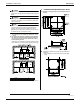
Specifications
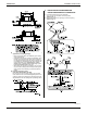

Installation of indoor unit EDUS281104
98 Installation of indoor / outdoor unit
3PN06240-3E
13
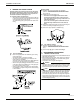
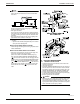
10-3 CONTROL BY 2 REMOTE CONTROLLERS
(Controlling 1 indoor unit by 2 remote controllers)
• When using 2 remote controllers, one must be set to “MAIN”
and the other to “SUB”.
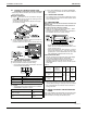
MAIN/SUB CHANGEOVER
(1) Insert a screw driver into the recess between the upper
and lower part of remote controller and, working from the 2
positions, pry off the upper part.
The remote controller PC board is attached to the upper
part of remote controller.
(2) Turn the MAIN/SUB changeover switch on one of the two
remote controllers PC boards to “S”.
(Leave the switch of the other remote controller set to “M”.)
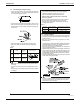
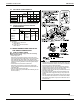
10-4 COMPUTERISED CONTROL (FORCED OFF
AND ON/OFF OPERATION)
See “FIELD SETTING” on page 13 for local settings.
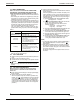
(1) Wire specifications and how to perform wiring
• Connect the input from outside to terminals T1 and T2 of
the transmission terminal block.
(2) Actuation
• The following table explains FORCED OFF and ON/OFF
OPERATIONS in response to Input A.
(3) How to select FORCED OFF and ON/OFF OPERATION
• Turn the power on and then use the remote controller to
select operation.
10-5 CENTRALIZED CONTROL
• For centralized control, it is necessary to designate the group
No. For details, refer to the manual of each optional control-
lers for centralized control.
11. FIELD SETTING
Make sure the control box lids are closed on the indoor and
outdoor units.
Field setting must be made from the remote controller in
accordance with the installation condition.
• Setting can be made by changing the “Mode No.”, “FIRST
CODE NO.”, and “SECOND CODE NO.”.
• For setting and operation, refer to the “FIELD SETTING” in
the installation manual of the remote controller.
• Set the remote controller to the field set mode. For
details, refer to the “HOW TO SET IN THE FIELD”, in the
remote controller manual.
• When in the field set mode, select mode No. 12, then set
the first code (switch) No. to “1”. Then set second code
(position) No. to “01” for FORCED OFF and “02” for ON/
OFF OPERATION. (FORCED OFF at factory set)
SETTING AIR FILTER SIGN
• Remote controllers are equipped with liquid crystal display
air filer signs to display the time to clean air filters.
• Change the SECOND CODE NO. according to Table 5
depending on the amount of dirt or dust in the room.
(SECOND CODE NO. is factory set to “01” for filter contam-
ination-light)
Ta b l e 5
〈
〈〈
〈When using wireless remote controllers〉
〉〉
〉
• When using wireless remote controllers, wireless remote
controller address setting is necessary. Refer to the installa-
tion manual attached to the wireless remote controller for
setting instructions.
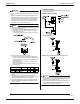
12. INSTALLATION OF THE DECORATION
PANEL
Refer to the installation manual attached to the decoration panel.
After installing the decoration panel, ensure that there is no
space between the unit body and decoration panel.
Wire specification Sheathed vinyl wire or cable (2 wires)
Gauge AWG 18-16
Length Max. 328ft.
External terminal
Contact that can ensure the minimum appli-
cable load of 15V DC, 10mA.
FORCED OFF ON/OFF OPERATION
Input “ON” stops operation (impossible by
remote controllers.)
Input OFF → ON turns
ON unit.
Input OFF enables control by remote con-
troller.
Input ON → OFF turns
OFF unit.
Setting
Spacing time of
display air
filter sign
(long life type)
Mode
No.
FIRST
CODE
NO.
SECOND
CODE
NO.
Air filter
contamination-
light
Approx. 2500 hrs
10
(20)
0
01
Air filter
contamination-
heavy
Approx. 1250 hrs 02