
Specifications
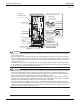

EDUS281104 Installation of indoor unit
Installation of indoor / outdoor unit 149
C: 3PN07521-2C
21 English
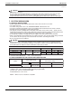
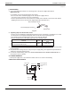
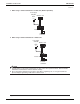
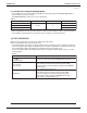
SETTING AIR FLOWRATE INCREASE MODE9-2
It is possible to raise set air fl ow (HIGH and LOW) from the fi eld. Change the SECOND CODE NO. as •
shown in Table 4 to suit your needs.
(SECOND CODE NO. is factory set to “01” for Standard.)
Table 4
Setting Mode No. FIRST CODE NO. SECOND CODE NO.
Standard
13 (23) 0
01
A little increase 02
Increase 03
〈
When using wireless remote controllers
〉
When using wireless remote controllers, wireless remote controller address setting is necessary. Refer to •
the installation manual attached to the wireless remote controller for setting instructions.
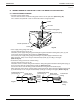
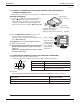
TEST OPERATION10.
Make sure the service lids are closed on the indoor and outdoor units.
Refer to the installation manual of the outdoor unit.
The operation lamp of the remote controller will fl ash when a malfunction occurs. Check the malfunction •
code on the liquid crystal display to identify the point of trouble. An explanation of malfunction codes and
the corresponding trouble is provided in the installation manual of the outdoor unit.
If any of the items in Table 5 are displayed, there may be a problem with the wiring or power, so check
the wiring again.
Table 5
Remote controller display Content
“
” (under centralized
control) is lit up
There is a short circuit at the FORCED OFF terminals (T1, T2). •
“U4” is lit up
“UH” is lit up
The power on the outdoor unit is off. •
The outdoor unit has not been wired for power supply. •
Incorrect wiring for the transmission wiring and/or FORCED •
OFF wiring.
The transmission wiring is cut. •
No display
The power on the indoor unit is off. •
The indoor unit has not been wired for power supply. •
Incorrect wiring for the remote controller wiring, the •
transmission wiring, and/or the FORCED OFF wiring.
The remote controller wiring is cut. •
If “U3” is lit up, the malfunction code shows the test operation has not been performed yet. •