
Specifications

EDUS281104 Installation of indoor unit
Installation of indoor / outdoor unit 143
3PN07521-2C
15 English
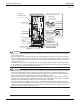
WIRING EXAMPLE AND HOW TO SET THE REMOTE CONTROLLER8.
HOW TO CONNECT WIRINGS8-1
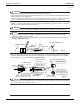
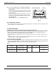
Conduit for power supply wiring •
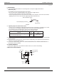
Unscrew and remove the conduit mounting plate from the electric parts box. (Refer to Fig. 20)
Fix a conduit to the plate with a lock nut and reattach them at original position.
Electric parts box
Refrigerant piping
Conduit
Lock nut
Conduit mounting plate
Screw
Fig. 20
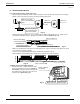
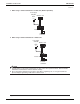
Power supply wiring and ground wiring •
Unscrew and remove the service lid.
Thread the power supply wiring and ground wiring through the included insulating tube (short) (7) and
secure them with the included clamp (small) (5). (Refer to Fig. 21)
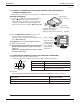
Connect the power supply wiring and ground wiring to the power supply terminal block (3P).
When doing this, fi rmly secure using the included clamp (small) (5) according to the fi gure.
(Refer to Fig. 22)
Transmission wiring and remote controller wiring •
Unscrew and remove the service lid.
Thread the remote controller wiring and transmission wiring through the included insulating tube (long) (7)
and secure them with the included clamp (small) (5). (Refer to Fig. 21)
Connect the remote controller wiring and the transmission wiring to the terminal block (6P).
When doing this, tie the remote controller wiring and the transmission wiring using the included clamp (small)
(5) and then fi rmly secure using the included clamp (small) (5) according to the fi gure. (Refer to Fig. 22)
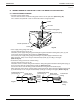
Insulating tube (short)
(accessory) (7)
Insulating tube (long)
(accessory) (7)
Clamp small
(accessory) (5)
Power
supply
wiring
Ground
wiring
Clamp small
(accessory) (5)
Tra nsmission
wiring
Remote
controller
wiring
Fig. 21
(1in.)
(1in.)