
Specifications
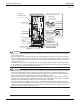

Installation of indoor unit EDUS281104
142 Installation of indoor / outdoor unit
3PN07521-2C
14English
CAUTION
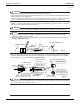
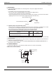
Drain piping connections •
Do not connect the drain piping directly to sewage pipes that smell of ammonia. The ammonia in the
sewage might enter the indoor unit through the drain pipes and corrode the heat exchanger.
Keep in mind that it will become the cause of getting drain pipe blocked if water collects on drain pipe.
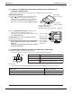
ELECTRIC WIRING WORK7.
GENERAL INSTRUCTIONS7-1
All fi eld supplied parts and materials and electric works must conform to local codes. •
Use copper wire only. •
For electric wiring work, refer to also “WIRING DIAGRAM” attached to the unit. •
For remote controller wiring details, refer to the installation manual attached to the remote controller. •
All wiring must be performed by an authorized electrician. •
This system consists of multiple indoor units. Mark each indoor unit as unit A, unit B..., and be sure the •
terminal block wiring to the outdoor unit and BS unit is properly matched. If wiring and piping between the
outdoor unit and indoor unit are mismatched, the system may cause a malfunction.
A circuit breaker capable of shutting down power supply to the entire system must be installed. •
Refer to the installation manual attached to the outdoor unit for the size of power supply wiring connected •
to the outdoor unit, the capacity of the circuit breaker and switch, and wiring instructions.
Be sure to ground the air conditioner. •
DANGER
Do not ground units to water pipes, telephone wires or lightning rods because incomplete grounding •
could cause a severe shock hazard resulting in severe injury or death, and to gas pipes because a gas
leak could result in an explosion which could lead to severe injury or death.
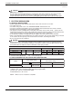
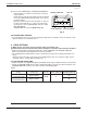
ELECTRICAL CHARACTERISTICS7-2
Units Power supply Fan motor
Model Hz Volts Voltage range MCA MFA W FLA
FAQ18PVJU
60 208-230
Max. 253
Min. 187
0.4 15 43 0.3
FAQ24PVJU 0.6 15 43 0.5
MCA: Min. Circuit Amps (A); MFA: Max. Fuse Amps (A)
W: Fan Motor Rated Output (W); FLA: Full Load Amps (A)
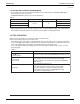
SPECIFICATIONS FOR FIELD SUPPLIED FUSES AND WIRE7-3
Model
Power supply wiring
Remote controller wiring
Transmission wiring
Field fuses
Size Wire Size
FAQ18PVJU
15A
Size must comply
with local codes.
Sheathed wire (2 wire)
AWG18-16
FAQ24PVJU
Allowable length of transmission wiring and remote controller wiring are as follows. •
(1) Outdoor unit - Indoor unit:Max.3280ft. (Total wiring length: 6560ft.)
(2) Indoor unit - Remote controller:Max.1640ft.
Insulated thickness: 1/16” or more.
./4%%ITHERAFUSEORABREAKERISACCEPTABLE