
Specifications
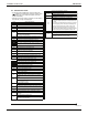
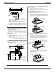
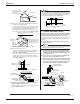
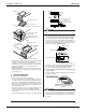

Installation of indoor unit EDUS281104
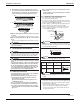
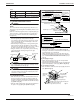
100 Installation of indoor / outdoor unit
3PN06240-3E
15
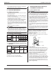
13-3 MALFUNCTION CODE
• For places where the Malfunction code is left blank, the
“ ” indication is not displayed. Though the system contin-
ues operating, be sure to inspect the system and make
repairs as necessary.
• Depending on the type of indoor or outdoor unit, the malfunc-
tion code may or may not be displayed.
Code Malfunction/Remarks
A1 Indoor unit’s PC board faulty
A3 Drain water level abnormal
A6 Indoor fan motor overloaded, overcurrent or locked.
A7 Air flow direction adjust motor is fault.
A9 Drive for electronic expansion valve is fault.
AJ
Type set improper
Capacity data is wrongly preset. Or there is nothing pro-
grammed in the data hold IC.
C4 Sensor R2T for heat exchanger temperature is fault.
C5 Sensor R3T for heat exchanger temperature is fault.
C9 Sensor R1T for suction air temperature is fault.
CJ
Sensor for remote controller is fault.
The remote controller thermistor does not function, but
the system thermo run is possible.
E3 High pressure abnormal (outdoor unit)
E4 Low pressure abnormal (outdoor unit)
E5 Compressor motor lock malfunction
E7
Outdoor fan motor lock malfunction
Outdoor fan instantaneous overcurrent malfunction
E9 Electronic expansion valve faulty (outdoor unit)
F3 Discharge pipe temperature abnormal (outdoor unit)
F6 The refrigerant is overcharged.
H9
Outdoor air thermistor faulty (outdoor unit)
J3
Discharge pipe thermistor faulty (outdoor unit)
J5 Suction pipe thermistor faulty (outdoor unit)
J6
Heat exchanger thermistor faulty (outdoor unit)
J9 Sensor for heat exchanger is fault.
JA Sensor for high pressure is fault.
JC Sensor for low pressure is fault.
L4
Overheated heat-radiating fin (outdoor)
Inverter cooling defect.
L5
Instantaneous overcurrent (outdoor)
Possible earth fault or short circuit in the compressor
motor.
L8
Electric thermal (outdoor)
Possible electrical overload in the compressor or cut line
in the compressor motor.
L9
Stall prevention (outdoor)
Compressor possibly locked.
LC
Transmission malfunction between the outdoor control
units’ inverters (outdoor)
P1 Open-phase (outdoor)
P3 PC board temperature sensor malfunction (outdoor)
P4
Heat-radiating fin temperature sensor malfunction
(outdoor)
PJ
Type set improper (outdoor unit)
Capacity data is wrongly preset. Or there is nothing pro-
grammed in the data hold IC.
U0
Suction pipe temperature abnormal
U2
Power source voltage malfunction
Includes the defect in K1M.
U3 The check operation has not performed.
U4
UF
Transmission error (indoor unit – outdoor unit)
Miswiring between indoor and outdoor units or malfunc-
tion of the PC board mounted on the indoor and the out-
door units.
If UF is shown, the wire between the indoor and outdoor
units is not properly wired. Therefore, immediately dis-
connect the power supply and correct the wire. (The
compressor and the fan mounted on the outdoor unit
may start operation independent of the remote controller
operation.) The power is not supplied to outdoor unit.
U9 Same transmission for in / outdoor unit is fault.
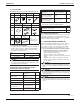
UA
Miss setting for multi system
Setting is wrong for selector switch of multi-system. (see
switch SS2 on the main unit’s PC board)