
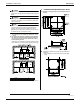
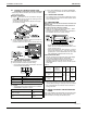
Specifications

EDUS281104 Installation of indoor unit
Installation of indoor / outdoor unit 99
3PN06240-3E
14
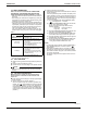
13. TEST OPERATION
Refer to the section of “FOR THE FOLLOWING ITEMS,
TAKE SPECIAL CARE DURING CONSTRUCTION AND
CHECK AFTER INSTALLATION IS FINISHED.” on page 4.
• Make sure if the service lids are closed on the indoor and out-
door units.
• After finishing the construction of refrigerant pipe, drain pipe
and electric wire, conduct the check operation referring to the
installation manual of the outdoor unit.
• The operation lamp of the remote controller will flash when a
malfunction occurs. Check the malfunction code on the liquid
crystal display to identify the point of trouble. An explanation
of malfunction codes and the corresponding trouble is pro-
vided in the installation manual of the outdoor unit.
If any of the items in Table 6 are displayed, there may be a
problem with the wiring or power, so check the wiring again.
Table 6
• If “U3” is lit up, the malfunction code shows the check oper-
ation has not been performed yet.
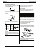
13-1 TEST OPERATION
(1) Make sure if the gas side and the liquid side stop valves are
open.
(2) Electrify crank case heater for 6 hours.
(3) Confirm function of unit according to the operation manual.
NOTE
• Refer to the diagnoses below if the unit does not operate
properly.
13-2 CAUTIONS FOR SERVICING
With the power on. Troubles can be monitored on the
remote controller or the LED’s on the PC board of the
indoor unit.
■ Trouble shooting with the display on the liquid crystal display
remote controller.
(1) With the wired remote controller. (NOTE 1)
When the operation stops due to trouble, operation lamp
flashed, and “ ” and the Malfunction code are indicated
on the liquid crystal display. In such a case, diagnose the
fault contents by referring to the table on the Malfunction
code list it case of group control, the unit No. is displayed so
that the indoor unit no with the trouble can be recognized.
(NOTE 2)
(2) With the wireless remote controller.
(Refer also to the operation manual attached to the wireless
remote controller)
When the operation stops due to trouble, the display on the
indoor unit flashes. In such a case, diagnose the fault con-
tents with the table on the Malfunction code list looking for
the Malfunction code which can be found by following pro-
cedures. (NOTE 2)
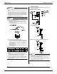
(1) Press the INSPECTION /TEST OPERATION button,
“ ” is displayed and “ 0 ” flashes.
(2) Press the PROGRAMMING TIME button and find the
unit No. which stopped due to trouble.
Number of beeps 3 short beeps Perform all the
following operations
1 short beep Perform (3) and (6)
1 long beep No trouble
(3) Press the OPERATION MODE SELECTOR button and
upper figure of the Malfunction code flashes.
(4) Continue pressing the PROGRAMMING TIME button
unit it makes 2 short beeps and find the upper code.
(5) Press the Operation selector button and lower figure of
the Malfunction code flashes.
(6) Continue pressing the PROGRAMMING TIME button
unit it makes a long beep and find the lower code.
• A long beep indicate the Malfunction code.
NOTE)
1. In case wired remote controller. Press the INSPECTION /
TEST OPERATION button on remote controller, “ ”
starts flashing.
2. Keep down the ON/OFF button for 5 seconds or longer in
the inspection mode and the above trouble history disap-
pears, after the trouble code goes on and off twice, followed
by the code “00”(normal).
The display changes from the inspection mode to the nor-
mal mode.
Remote control display Content
“ ” (under cen-
tralized control) is lit up.
• There is a short circuit at the FORCED OFF
terminals (T1, T2)
“U4” is lit up
“UH” is lit up
• The power on the outdoor unit is off.
• The outdoor unit has not been wired for
power supply.
• Incorrect wiring for the transmission wiring
and / or FORCED OFF wiring.
• The transmission wiring is cut.
No display
• The power on the indoor unit is off.
• The indoor unit has not been wired for
power supply.
• Incorrect wiring for the remote controller
wiring, the transmission wiring and / or the
FORCED OFF wiring.
• The remote controller wiring is cut.