EDUS281104 Cooling Only 60Hz Heat Pump 60Hz RZR-P, RZQ-P(9) series AMERICAS
EDUS281104 SkyAir Engineering Data 1. External appearance ..................................................................................3 1.1 Indoor unit .................................................................................................... 3 1.2 Outdoor unit.................................................................................................. 4 2. Model name, power supply and nomenclature ...........................................5 2.1 Model name and power supply ..........
EDUS281104 11.Operation limits ......................................................................................... 66 12.Accessories...............................................................................................68 12.1 12.2 12.3 12.4 Indoor unit .................................................................................................. 68 Outdoor unit................................................................................................ 69 Indoor unit ................
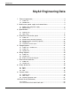
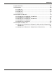
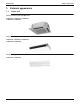
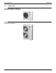
EDUS281104 External appearance 1. External appearance 1.
External appearance 1.
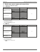
EDUS281104 Model name, power supply and nomenclature 2. Model name, power supply and nomenclature 2.1 Model name and power supply 2.1.
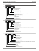
Model name, power supply and nomenclature 2.
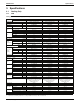
EDUS281104 Specifications 3. Specifications 3.1 Cooling Only 3.1.1 FCQ Ceiling mounted cassette type (Multi flow) Model Indoor unit FCQ18PVJU FCQ24PVJU Outdoor unit RZR18PVJU RZR24PVJU RZR30PVJU 1 phase, 208/230V, 60Hz 1 phase, 208/230V, 60Hz 1 phase, 208/230V, 60Hz Power supply Cooling capacity 1 Btu/h Indoor unit Dimensions H×W×D in.
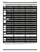
Specifications EDUS281104 Ceiling mounted cassette type (Multi flow), continued Model Indoor unit FCQ36MVJU Outdoor unit RZR36PVJU RZR42PVJU 1 phase, 208/230V, 60Hz 1 phase, 208/230V, 60Hz Power supply Cooling capacity 1 Btu/h Indoor unit Dimensions H×W×D in. (mm) Type Coil Rows×Stages×FPI Face area ft² (m²) Model Fan Type Motor output Airflow rate (H/L) Piping connections QTS45A17M Turbo fan Turbo fan 90 1,030/870 — — Lbs (kg) 74 (33.6) 74 (33.6) φ3/8 (9.
EDUS281104 3.1.2 Specifications FHQ Ceiling suspended type Model Indoor unit FHQ18PVJU FHQ24PVJU Outdoor unit RZR18PVJU RZR24PVJU RZR30PVJU 1 phase, 208/230V, 60Hz 1 phase, 208/230V, 60Hz 1 phase, 208/230V, 60Hz Power supply Cooling capacity 1 Btu/h Indoor unit Color Dimensions H×W×D in. (mm) Type Coil Rows×Stages×FPI Face area Fan ft² (m²) Cross fin coil Cross fin coil 2 × 12 × 15 + 2 × 10 × 15 2 × 12 × 15 + 2 × 10 × 15 3.66 + 2.95 (1.1 x 0.
Specifications EDUS281104 Ceiling suspended type, continued Model Indoor unit FHQ36MVJU Outdoor unit RZR36PVJU RZR42PVJU 1 phase, 208/230V, 60Hz 1 phase, 208/230V, 60Hz Power supply Cooling capacity 1 Btu/h Indoor unit Color Dimensions H×W×D in. (mm) Type Coil Rows×Stages×FPI Face area Fan ft² (m²) Motor output 3.66 + 2.95 (1.1 + 0.9) W 130 130 830/670 850/700 Resin net (With mold resistant) Resin net (With mold resistant) Lbs (kg) 90 (41) 90 (41) in. (mm) φ3/8 (9.
EDUS281104 3.1.3 Specifications FAQ Wall mounted type Model Indoor unit FAQ18PVJU Outdoor unit RZR18PVJU RZR24PVJU 1 phase, 208/230V, 60Hz 1 phase, 208/230V, 60Hz Power supply Cooling capacity 1 Btu/h Indoor unit Color Dimensions H×W×D in. (mm) Type Coil Rows×Stages×FPI Face area ft² (m²) Model Fan Type Motor output Airflow rate (H/L) Liquid Piping connections 2.29 (0.
Specifications EDUS281104 3.2 Heat Pump 3.2.
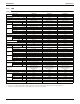
EDUS281104 Specifications Ceiling mounted cassette type (Multi flow), continued Model Indoor unit FCQ36MVJU FCQ42MVJU Outdoor unit RZQ36PVJU9 RZQ42PVJU9 Power supply 1 phase, 208/230V, 60Hz 1 phase, 208/230V, 60Hz Cooling capacity 1 Btu/h 36,000 40,500 Heating capacity 2 Btu/h 39,500 41,500 FCQ36MVJU FCQ36MVJU 11–3/8 × 33–1/8 × 33–1/8 (289 x 841 x 841) 11–3/8 × 33–1/8 × 33–1/8 (289 x 841 x 841) Cross fin coil Cross fin coil 2 × 12 × 17 2 × 12 × 17 Indoor unit Dimensions H×W×D i
Specifications 3.2.2 EDUS281104 FHQ Ceiling suspended type Model Indoor unit FHQ18PVJU FHQ24PVJU Outdoor unit RZQ18PVJU9 RZQ24PVJU9 RZQ30PVJU 1 phase, 208/230V, 60Hz 1 phase, 208/230V, 60Hz 1 phase, 208/230V, 60Hz 30,000 Power supply FHQ30PVJU Cooling capacity 1 Btu/h 18,000 24,000 Heating capacity 2 Btu/h 20,000 27,000 34,000 FHQ18PVJU FHQ24PVJU FHQ30PVJU Indoor unit Color Dimensions H×W×D in.
EDUS281104 Specifications Ceiling suspended type, continued Model Indoor unit FHQ36MVJU FHQ42MVJU Outdoor unit RZQ36PVJU9 RZQ42PVJU9 Power supply 1 phase, 208/230V, 60Hz 1 phase, 208/230V, 60Hz Cooling capacity 1 Btu/h 36,000 40,500 Heating capacity 2 Btu/h 37,500 39,500 FHQ36MVJU FHQ42MVJU Indoor unit Color Dimensions H×W×D in.
Specifications 3.2.3 EDUS281104 FAQ Wall mounted type Model Indoor unit FAQ18PVJU FAQ24PVJU Outdoor unit RZQ18PVJU9 RZQ24PVJU9 Power supply 1 phase, 208/230V, 60Hz 1 phase, 208/230V, 60Hz Cooling capacity 1 Btu/h 18,000 24,000 Heating capacity 2 Btu/h 20,000 26,000 FAQ18PVJU FAQ24PVJU Indoor unit Color Dimensions H×W×D in.
EDUS281104 Dimensions and service space 4. Dimensions and service space 4.1 Indoor unit 4.1.1 FCQ (Ceiling mounted cassette type) RZR-P, RZQ-P(9) 3D042633B Unit (in.
Dimensions and service space 4.1.2 EDUS281104 FHQ (Ceiling suspended type) Hanger bracket Unit (in.
EDUS281104 4.1.3 Dimensions and service space FAQ (Wall mounted type) Front grille Unit (in.
Dimensions and service space 4.2 EDUS281104 Wired remote controller (Optional) 20 3D065275 Unit (in.
EDUS281104 4.3 Dimensions and service space Wireless remote controller (Optional) RZR-P, RZQ-P(9) 3D049735 Unit (in.
Dimensions and service space EDUS281104 22 3D049336 Unit (in.
EDUS281104 Dimensions and service space RZR-P, RZQ-P(9) 3D049736 Unit (in.
Dimensions and service space 4.4 EDUS281104 Outdoor unit 24 3D064212A Unit (in.
EDUS281104 Dimensions and service space RZR-P, RZQ-P(9) 3D065351A Unit (in.
Dimensions and service space 4.
EDUS281104 Dimensions and service space 3D064213A RZR-P, RZQ-P(9) 27
Dimensions and service space EDUS281104 3D064213A 28 RZR-P, RZQ-P(9)
EDUS281104 Dimensions and service space RZR36PVJU / RZR42PVJU RZQ36PVJU9 / RZQ42PVJU9 3D047381B RZR-P, RZQ-P(9) 29
Dimensions and service space EDUS281104 3D047381B 30 RZR-P, RZQ-P(9)
EDUS281104 Piping diagrams 5. Piping diagrams 5.
Piping diagrams 5.
EDUS281104 5.
Wiring diagrams EDUS281104 6. Wiring diagrams 6.
EDUS281104 Wiring diagrams 3D048116A FHQ18PVJU / FHQ24PVJU / FHQ30PVJU FHQ36MVJU / FHQ42MVJU RZR-P, RZQ-P(9) 35
Wiring diagrams EDUS281104 3D046039D FAQ18PVJU / FAQ24PVJU 36 RZR-P, RZQ-P(9)
EDUS281104 6.
Wiring diagrams EDUS281104 GROUND GROUND 3D071178 RZR36PVJU / RZR42PVJU RZQ36PVJU9 / RZQ42PVJU9 38 RZR-P, RZQ-P(9)
EDUS281104 6.
Wiring diagrams EDUS281104 RZR36PVJU / RZR42PVJU RZQ36PVJU9 / RZQ42PVJU9 FUSE / BREAKER FUSE / BREAKER 3D071667 40 RZR-P, RZQ-P(9)
EDUS281104 Electrical characteristics 7. Electrical characteristics 7.1 Indoor unit FCQ18PVJU / FCQ24PVJU / FCQ30PVJU FCQ36MVJU / FCQ42MVJU 5. Either a fuse or a circuit breaker is acceptable.
Electrical characteristics EDUS281104 FHQ18PVJU / FHQ24PVJU / FHQ30PVJU FHQ36MVJU / FHQ42MVJU 5. Either a fuse or a circuit breaker is acceptable.
EDUS281104 Electrical characteristics FAQ18PVJU / FAQ24PVJU 5. Either a fuse or a circuit breaker is acceptable.
Electrical characteristics 7.2 EDUS281104 Outdoor unit RZR18PVJU / RZR24PVJU / RZR30PVJU RZQ18PVJU9 / RZQ24PVJU9 / RZQ30PVJU Model Units Outdoor H/P C/O Hz RZQ18PVJU9 H/P 60 RZQ24PVJU9 H/P 60 RZQ30PVJU H/P 60 RZR18PVJU C/O 60 RZR24PVJU C/O 60 RZR30PVJU C/O 60 Power Supply Volts Min. Max 208 187 229 230 209 253 208 187 229 230 209 253 208 187 229 230 209 253 208 187 229 230 209 253 208 187 229 230 209 253 208 187 229 230 209 253 Comp.
EDUS281104 Electrical characteristics RZR36PVJU / RZR42PVJU RZQ36PVJU9 / RZQ42PVJU9 Model Units Power Supply Comp. Outdoor H/P C/O Hz Volts Min. Max MCA MOP MSC RLA RZQ36PVJU9 H/P 60 208/230 187 253 27.0 30 − 18.6 RZQ42PVJU9 H/P 60 208/230 187 253 27.0 30 − 19.6 RZR36PVJU C/O 60 208/230 187 253 27.0 30 − 18.6 RZR42PVJU C/O 60 208/230 187 253 27.0 30 − 19.6 NOTES: 1.
Safety devices list EDUS281104 8. Safety devices list 8.
EDUS281104 8.
Safety devices list 8.
EDUS281104 Capacity tables 9. Capacity tables 9.1 Cooling Only 9.1.1 FCQ FCQ18PVJU + RZR18PVJU Cooling Capacity Indoor Air Temp. 68 TC SHC EDB(˚FDB) EWB(˚FWB) k B T U H M B h 57.0 11.68 10.3 68.0 61.0 14.21 11.1 72.0 64.0 16.10 11.9 77.0 67.0 18.00 12.8 80.0 72.0 20.79 13.6 86.0 75.0 21.14 13.6 90.0 230V–60Hz PI kW 0.63 0.74 0.83 0.95 1.14 1.14 77 TC SHC kBTUH MBh 11.68 10.3 14.21 11.1 16.10 11.9 18.00 12.8 20.06 13.4 20.41 13.3 PI kW 0.67 0.83 0.96 1.10 1.25 1.
Capacity tables EDUS281104 FCQ30PVJU + RZR30PVJU Cooling Capacity Indoor Air Temp. 68 TC SHC EDB(˚FDB) EWB(˚FWB) k B T U H M B h 57.0 19.47 16.8 68.0 61.0 23.68 20.1 72.0 64.0 26.84 21.2 77.0 67.0 30.00 23.1 80.0 72.0 34.65 24.4 86.0 75.0 35.24 22.2 90.0 230V–60Hz PI kW 1.24 1.50 1.71 1.97 2.39 2.40 77 TC SHC kBTUH MBh 19.47 16.8 23.68 20.1 26.84 21.2 30.00 23.1 33.43 23.7 34.02 21.4 PI kW 1.35 1.69 1.99 2.31 2.64 2.66 Outdoor Air 86 TC SHC PI kBTUH MBh kW 1.55 19.47 16.8 1.96 23.68 20.1 2.31 26.
EDUS281104 9.1.2 Capacity tables FHQ FHQ18PVJU + RZR18PVJU Cooling Capacity Indoor Air Temp. 68 TC SHC EDB(˚FDB) EWB(˚FWB) k B T U H M B h 57.0 11.68 10.6 68.0 61.0 14.21 11.9 72.0 64.0 16.10 12.7 77.0 67.0 18.00 13.3 80.0 72.0 20.79 14.2 86.0 75.0 21.14 13.5 90.0 230V–60Hz PI kW 0.61 0.58 0.67 0.78 0.96 0.97 77 TC SHC kBTUH MBh 11.68 10.6 14.21 11.9 16.10 12.7 18.00 13.3 20.06 14.0 20.41 13.2 PI kW 0.65 0.80 0.93 1.07 1.22 1.22 Outdoor Air 86 TC SHC PI kBTUH MBh kW 0.74 11.68 10.6 0.92 14.21 11.
Capacity tables EDUS281104 FHQ36MVJU + RZR36PVJU Cooling Capacity Indoor Air Temp. 230V–60Hz 68 TC EDB(˚FDB) EWB(˚FWB) M B h 23.4 57.0 68.0 28.4 61.0 72.0 32.2 64.0 77.0 36.0 67.0 80.0 41.6 72.0 86.0 42.3 75.0 90.0 77 PI kW 1.40 1.70 1.94 2.25 2.73 2.75 TC MBh 23.4 28.4 32.2 36.0 40.1 40.8 PI kW 1.52 1.93 2.27 2.64 3.03 3.05 Outdoor Air Temp. ˚FDB 86 90 TC PI TC PI MBh kW MBh kW 23.4 1.87 23.4 1.76 28.4 2.39 28.4 2.24 32.2 2.83 32.2 2.64 36.0 3.31 36.0 3.09 38.0 3.47 38.6 3.34 38.7 3.49 39.4 3.
EDUS281104 9.1.3 Capacity tables FAQ FAQ18PVJU + RZR18PVJU Cooling Capacity Indoor Air Temp. 68 TC SHC EDB(˚FDB) EWB(˚FWB) k B T U H M B h 57.0 11.68 8.9 68.0 61.0 14.21 11.7 72.0 64.0 16.10 12.7 77.0 67.0 18.00 13.7 80.0 72.0 20.79 14.1 86.0 75.0 21.14 12.8 90.0 230V–60Hz PI kW 0.60 0.74 0.84 0.98 1.19 1.20 77 TC SHC kBTUH MBh 11.68 8.9 14.21 11.7 16.10 12.7 18.00 13.7 20.06 14.1 20.41 12.8 PI kW 0.66 0.84 0.99 1.15 1.33 1.34 Outdoor Air 86 TC SHC PI kBTUH MBh kW 0.76 11.68 8.9 0.97 14.21 11.
Capacity tables EDUS281104 9.2 Heat Pump 9.2.1 FCQ FCQ18PVJU + RZQ18PVJU9 Cooling Capacity Indoor Air Temp. 68 TC SHC EDB(˚FDB) EWB(˚FWB) k B T U H M B h 57.0 11.68 10.3 68.0 61.0 14.21 11.1 72.0 64.0 16.10 11.9 77.0 67.0 18.00 12.8 80.0 72.0 20.79 13.6 86.0 75.0 21.14 13.6 90.0 Heating Capacity Indoor Air Temp. EDB(˚FDB) 61 64 68 70 72 75 230V–60Hz PI kW 0.63 0.74 0.83 0.95 1.14 1.14 23 PI kW 2.80 2.64 2.42 2.32 2.21 2.06 PI kW 0.67 0.83 0.96 1.10 1.25 1.
EDUS281104 Capacity tables FCQ30PVJU + RZQ30PVJU Cooling Capacity Indoor Air Temp. 68 TC SHC EDB(˚FDB) EWB(˚FWB) k B T U H M B h 57.0 19.47 16.8 68.0 61.0 23.68 20.1 72.0 64.0 26.84 21.2 77.0 67.0 30.00 23.1 80.0 72.0 34.65 24.4 86.0 75.0 35.24 22.2 90.0 Heating Capacity Indoor Air Temp. EDB(˚FDB) 61 64 68 70 72 75 230V–60Hz PI kW 1.24 1.50 1.71 1.97 2.39 2.40 23 PI kW 2.72 2.80 2.91 2.96 3.02 3.10 PI kW 1.35 1.69 1.99 2.31 2.64 2.66 Outdoor Air 86 TC SHC PI kBTUH MBh kW 1.55 19.47 16.8 1.96 23.
Capacity tables EDUS281104 FCQ42MVJU + RZQ42PVJU9 Cooling Capacity Indoor Air Temp. 68 TC EDB(˚FDB) EWB(˚FWB) M B h 26.3 57.0 68.0 32.0 61.0 72.0 36.2 64.0 77.0 40.5 67.0 80.0 46.8 72.0 86.0 47.6 75.0 90.0 77 PI kW 1.94 2.36 2.70 3.12 3.80 3.82 Heating Capacity Indoor Air Temp. EDB(˚FDB) 61 64 68 70 72 75 230V–60Hz TC MBh 26.3 32.0 36.2 40.5 45.1 45.9 23 PI kW 3.53 3.64 3.77 3.84 3.91 4.01 95 TC MBh 26.3 32.0 36.2 40.5 41.8 42.6 104 PI kW 2.80 3.60 4.28 5.01 5.07 5.10 TC MBh 26.3 32.0 36.2 38.
EDUS281104 9.2.2 Capacity tables FHQ FHQ18PVJU + RZQ18PVJU9 Cooling Capacity Indoor Air Temp. 68 TC SHC EDB(˚FDB) EWB(˚FWB) k B T U H M B h 57.0 11.68 10.6 68.0 61.0 14.21 11.9 72.0 64.0 16.10 12.7 77.0 67.0 18.00 13.3 80.0 72.0 20.79 14.2 86.0 75.0 21.14 13.5 90.0 Heating Capacity Indoor Air Temp. EDB(˚FDB) 61 64 68 70 72 75 230V–60Hz PI kW 0.61 0.58 0.67 0.78 0.96 0.97 23 PI kW 2.77 2.61 2.39 2.29 2.19 2.04 PI kW 0.65 0.80 0.93 1.07 1.22 1.22 Outdoor Air 86 TC SHC PI kBTUH MBh kW 0.74 11.
Capacity tables EDUS281104 FHQ30PVJU + RZQ30PVJU Cooling Capacity Indoor Air Temp. 68 TC SHC EDB(˚FDB) EWB(˚FWB) k B T U H M B h 57.0 19.47 15.6 68.0 61.0 23.68 18.5 72.0 64.0 26.84 19.9 77.0 67.0 30.00 21.1 80.0 72.0 34.65 21.8 86.0 75.0 35.24 21.1 90.0 Heating Capacity Indoor Air Temp. EDB(˚FDB) 61 64 68 70 72 75 230V–60Hz PI kW 1.15 1.40 1.59 1.84 2.23 2.25 23 PI kW 2.97 3.06 3.18 3.24 3.30 3.39 PI kW 1.25 1.58 1.86 2.16 2.48 2.49 Outdoor Air 86 TC SHC PI kBTUH MBh kW 1.44 19.47 15.6 1.83 23.
EDUS281104 Capacity tables FHQ42MVJU + RZQ42PVJU9 Cooling Capacity Indoor Air Temp. 68 TC EDB(˚FDB) EWB(˚FWB) M B h 26.3 57.0 68.0 32.0 61.0 72.0 36.2 64.0 77.0 40.5 67.0 80.0 46.8 72.0 86.0 47.6 75.0 90.0 77 PI kW 1.66 2.02 2.31 2.67 3.26 3.28 Heating Capacity Indoor Air Temp. EDB(˚FDB) 61 64 68 70 72 75 230V–60Hz TC MBh 26.3 32.0 36.2 40.5 45.1 45.9 23 PI kW 3.48 3.58 3.71 3.78 3.85 3.95 95 TC MBh 26.3 32.0 36.2 40.5 41.8 42.6 104 PI kW 2.40 3.09 3.67 4.30 4.35 4.38 TC MBh 26.3 32.0 36.2 38.
Capacity tables 9.2.3 EDUS281104 FAQ FAQ18PVJU + RZQ18PVJU9 Cooling Capacity Indoor Air Temp. 68 TC SHC EDB(˚FDB) EWB(˚FWB) k B T U H M B h 57.0 11.68 8.9 68.0 61.0 14.21 11.7 72.0 64.0 16.10 12.7 77.0 67.0 18.00 13.7 80.0 72.0 20.79 14.1 86.0 75.0 21.14 12.8 90.0 Heating Capacity Indoor Air Temp. EDB(˚FDB) 61 64 68 70 72 75 230V–60Hz PI kW 0.60 0.74 0.84 0.98 1.19 1.20 23 PI kW 3.59 3.36 3.08 2.94 2.80 2.60 PI kW 0.66 0.84 0.99 1.15 1.33 1.34 Outdoor Air 86 TC SHC PI kBTUH MBh kW 0.76 11.68 8.
EDUS281104 9.
Capacity tables EDUS281104 3D071685 RZR36PVJU / RZR42PVJU 62 RZR-P, RZQ-P(9)
EDUS281104 Capacity tables C: 3D047383B RZQ36PVJU9 / RZQ42PVJU9 RZR-P, RZQ-P(9) 63
Sound Levels (Reference) EDUS281104 10. Sound Levels (Reference) 10.1 Overall Location of microphone RZQ36PVJU9 / RZQ42PVJU9 RZR36PVJU / RZR42PVJU Location of microphone RZQ18PVJU9 / RZQ24PVJU9 / RZQ30PVJU RZR18PVJU / RZR24PVJU / RZR30PVJU MIC. POSITION 3.3 ft (1 m) 4.9 ft (1.5 m) MIC. POSITION 4.9 ft (1.5 m) 3.
EDUS281104 Sound Levels (Reference) RZQ42PVJU9 / RZR42PVJU RZR-P, RZQ-P(9) 65
Operation limits EDUS281104 11. Operation limits Range for continuous operation RZR18PVJU / RZR24PVJU / RZR30PVJU RZQ18PVJU9 / RZQ24PVJU9 / RZQ30PVJU C: 3D064229A NOTE: Operation can be extended to 0°F in cooling with use of the optional wind baffle.
EDUS281104 Operation limits Range for continuous operation RZR36PVJU / RZR42PVJU RZQ36PVJU9 / RZQ42PVJU9 C: 3D065369A NOTE: Operation can be extended to 0°F in cooling with use of the optional wind baffle.
Accessories EDUS281104 12. Accessories 12.1 Indoor unit 12.1.1 FCQ Optional accessories (For unit) No.
EDUS281104 Accessories 12.1.2 FHQ Optional accessories (For unit) Model No. Item 1 Replacement long life filter FHQ18PVJU FHQ24PVJU FHQ30PVJU FHQ36MVJU FHQ42MVJU Resin net KAF501DA160 Optional accessories (For controls) Model No.
EDUS281104 13. Center of gravity 13.1 Indoor unit FCQ18PVJU / FCQ24PVJU / FCQ30PVJU FCQ36MVJU / FCQ42MVJU Unit (in.
EDUS281104 13.2 Outdoor unit RZR18PVJU / RZR24PVJU / RZR30PVJU RZQ18PVJU9 / RZQ24PVJU9 / RZQ30PVJU Unit (in.
EDUS281104 RZR36PVJU / RZR42PVJU RZQ36PVJU9 / RZQ42PVJU9 Unit (in.
EDUS281104 Installation of indoor unit 14. Installation of indoor unit 14.1 FCQ18PVJU / FCQ24PVJU / FCQ30PVJU SPLIT SYSTEM Air Conditioners CONTENTS 1. 2. 3. 4. 5. 6. 7. 8. 9. 10. 11. 12. 13. 1. SAFETY CONSIDERATIONS ........................................... 1 BEFORE INSTALLATION .................................................. 2 SELECTING INSTALLATION SITE ................................... 3 PREPARATIONS BEFORE INSTALLATION .....................
Installation of indoor unit • When wiring the power supply and connecting the remote controller wire and transmission wire, position the wires so that the control box lid can be securely fastened. Improper positioning of the control box lid may result in electric shocks, fire or the terminals overheating. • Before touching electrical parts, turn off the unit. • Do not touch the switch with wet fingers. Touching a switch with wet fingers can cause electric shock. • Be sure to install an earth leakage breaker.
EDUS281104 Installation of indoor unit • This unit, both indoor and outdoor, is suitable for installation in a commercial and light industrial environment. If installed as a household appliance it could cause electromagnetic interference. Table 2 Remote controller Wired type Wireless type BRC1C71 BRC7C812 WARNING • Entrust installation to the place of purchase or a qualified person. Improper installation could lead to leak and, in worse cases, electric shock of fire.
Installation of indoor unit EDUS281104 4. PREPARATIONS BEFORE INSTALLATION (1) Relation of ceiling opening to unit and suspension bolt position 33 1/16 (Indoor unit) Refrigerant pipe 30 11/16 (Suspension bolt pitch) WARNING • If the supporting structural members are not strong enough to take the unit’s weight, the unit could fall out of place and cause serious injury. H 11 3/4 or more (length: in.
EDUS281104 Installation of indoor unit Installation example ® 33 13/16 (Opening dimension inside the frame for ceiling) Ceiling slap 1 15/16 3 15/16 Anchor Long nut or turn-buckle Frame False ceiling Suspension bolt False ceiling NOTE) All the above parts are field supplied. 13/16 or more 33 13/16-*35 13/16 (Ceiling opening dimension) 13/16 or more (Ceiling-panel overlapping dimension) (length: in.) 5.
Installation of indoor unit EDUS281104 6-1 Insulation (field supply) Put the insulation tightly around the hole of the unit as shown. The ends of the side plate and the inner insulation must be completely adhered without leaving any clearance along the circumference of the hole. Inner insulation For new ceilings (2) • Refer to the paper pattern for installation (5) for ceiling opening dimension. Consult the builder or carpenter for details.
EDUS281104 7. Installation of indoor unit REFRIGERANT PIPING WORK 7-1 NOTE GENERAL INSTRUCTIONS • For refrigerant pipe of outdoor units, see the installation manual attached to the outdoor unit. • Before refrigerant piping work, check which type of refrigerant is used. Proper operation is not possible if the types of refrigerant are not the same. • The outdoor unit is charged with refrigerant.
Installation of indoor unit EDUS281104 CAUTION 1/100 gradient or more 3.28 - 4.92ft. • Be sure to insulate any field piping all the way to the piping connection inside the unit. Any exposed pipe may cause condensate or burns if touched. 7-4 Brazing refrigerant piping • Before brazing local refrigerant pipe, nitrogen gas shall be blown through the pipe to expel air from the pipe.
EDUS281104 Installation of indoor unit Power supply terminal block NOTE • The incline of attached drain hose (1) should be 2 15/16 in. or less so that the drain socket does not have to stand additional force. 2 15/16 or less 29 1/2 or less Drain hose (1) (accessory) (length: in.) Select converging drain pipe whose gauge is suitable for the operating capacity of the unit. • Drain pipe connections Do not connect the drain pipe directly to sewage pipes that smell of ammonia.
Installation of indoor unit 9-3 EDUS281104 SPECIFICATIONS FOR FIELD SUPPLIED FUSES AND WIRES Power supply wiring Field fuses Size Model FCQ18PVJU FCQ24PVJU FCQ30PVJU 15A Clamp A Transmission wiring Wire Wire size must comply Sheathed wire with local (2 wires) codes. P1 P2 10.
EDUS281104 Installation of indoor unit 1. When using 1 remote controller for 1 indoor unit. (Normal operation) Connect wires of the same gauge to both sides. Power Supply 208-230V ~ Outdoor unit Control box 60Hz IN/D OUT/D F1 F2 F1 F2 L1 L2 2. Tightening torque for the terminal screws. • Use the correct screwdriver for tightening the terminal screws. If the blade of screwdriver is too small, the head of the screw might be damaged, and the screw will not be properly tightened.
Installation of indoor unit EDUS281104 (2) Turn the MAIN/SUB changeover switch on one of the two remote controllers PC boards to “S”. (Leave the switch of the other remote controller set to “M”.) (Factory setting) S M Remote controller PC board Only one remote controller needs to be changed if factory settings have remained untouched. S M 11. FIELD SETTING Make sure the control box lids are closed on the indoor and outdoor units.
EDUS281104 Installation of indoor unit 13. TEST OPERATION Refer to the section of “FOR THE FOLLOWING ITEMS, TAKE SPECIAL CARE DURING CONSTRUCTION AND CHECK AFTER INSTALLATION IS FINISHED.” on page 3. • Make sure if the service lids are closed on the indoor and outdoor units. • After finishing the construction of refrigerant pipe, drain pipe and electric wire, conduct the check operation referring to the installation manual of the outdoor unit.
Installation of indoor unit E5 E7 E9 F3 F6 H9 J3 J5 J6 J9 JA JC L4 L5 L8 L9 LC P1 P3 P4 PJ U0 U2 U3 U4 UF U9 UA English EDUS281104 Compressor motor lock malfunction Outdoor fan motor lock malfunction Outdoor fan instantaneous overcurrent malfunction Electronic expansion valve faulty (outdoor unit) Discharge pipe temperature abnormal (outdoor unit) The refrigerant is overcharged.
EDUS281104 14.2 Installation of indoor unit FCQ36MVJU / FCQ42MVJU SPLIT SYSTEM Air Conditioners CONTENTS 1. 2. 3. 4. 5. 6. 7. 8. 9. 10. 11. 12. 13. 1. SAFETY CONSIDERATIONS ..........................................2 BEFORE INSTALLATION ................................................3 SELECTING INSTALLATION SITE..................................4 PREPARATIONS BEFORE INSTALLATION....................5 INSTALLATION PROCEDURES FOR FRESH AIR INTAKE DUCT CONNECTION .................................
Installation of indoor unit • Do not install the air conditioner in the following locations: (a) where a mineral oil mist or an oil spray or vapor is produced, for example in a kitchen Plastic parts may deteriorate and fall off or result in water leakage. (b) where corrosive gas, such as sulfurous acid gas, is produced Corroding copper pipes or soldered parts may result in refrigerant leakage.
EDUS281104 2-1 Installation of indoor unit ACCESSORIES Check the following accessories are included with your unit. Name (1) Drain hose (2) Metal clamp (3) Washer for hanger bracket (4) Clamp Quantity 1 pc. 1 pc. 8 pcs. 4 pcs. a. Items to be checked after completion of work Shape Name (5) Paper pattern for installation (6) Screws (M5) (7) Washer fixing plate Insulation for fitting 1 pc. 4 pcs. 4 pcs.
Installation of indoor unit EDUS281104 4. DANGER • Do not install unit in an area where flammable materials are present due to the risk explosion resulting in serious injury or death. PREPARATIONS BEFORE INSTALLATION (1) Relation of ceiling opening to unit and suspension bolt position WARNING • If the supporting structural members are not strong enough to take the unit’s weight, the unit could fall out of place and cause serious injury.
EDUS281104 Installation of indoor unit 5. INSTALLATION PROCEDURES FOR FRESH AIR INTAKE DUCT CONNECTION (1) Cut off the knockout hole on the side plate. Then, cut the inner insulation of the hole portion. (Refer to Fig. 1) (2) Adhere the insulation for opening of unit to the opening. (Refer to Fig. 2) (2) Make the ceiling opening needed for installation where applicable. (For existing ceilings) • Refer to the paper pattern for installation (5) for ceiling opening dimensions.
Installation of indoor unit 6. INDOOR UNIT INSTALLATION Installing optional accessories (except for the decoration panel) before installing the indoor unit is easier. However, for existing ceilings, install fresh air inlet component kit and branch duct before installing the unit. (1) Install the indoor unit temporarily. • Attach the hanger bracket to the suspension bolt. Be sure to fix it securely by using a nut and washer from the upper and lower sides of the hanger bracket.
EDUS281104 7-2 Installation of indoor unit Connecting the refrigerant pipe • When connecting the flare nut, coat the flare both inside and outside with ester oil or ether oil and initially tighten by hand 3 or 4 turns before tightening firmly. Not recommended but in case of emergency You must use a torque wrench but if you are obliged to install the unit without a torque wrench, you may follow the installation method mentioned below.
Installation of indoor unit 7-4 EDUS281104 Brazing refrigerant piping • Before brazing local refrigerant pipe, nitrogen gas shall be blown through the pipe to expel air from the pipe. If your brazing is done without nitrogen gas blowing, a large amount of oxide film develops inside the pipe, and could cause system malfunction. • When brazing the refrigerant pipe, only begin brazing after having carried out nitrogen substitution or while inserting nitrogen into the refrigerant pipe.
EDUS281104 Installation of indoor unit NOTE • The incline of attached drain hose (1) should be 2 15/16 in. or less so that the drain socket does not have to stand additional force. Select converging drain pipe whose gauge is suitable for the operating capacity of the unit. • Drain pipe connections Do not connect the drain pipe directly to sewage pipes that smell of ammonia. The ammonia in the sewage might enter the indoor unit through the drain pipe and corrode the heat exchanger.
Installation of indoor unit 9-2 EDUS281104 ELECTRICAL CHARACTERISTICS Power supply Units Model Hz Volts Voltage range 60 208230V Max. 253 Min. 187 MCA FCQ24MVJU FCQ30MVJU FCQ36MVJU FCQ42MVJU Fan motor MFA KW FLA 1.3 15 0.09 1.0 1.3 15 0.09 1.0 1.4 15 0.09 1.1 1.4 15 0.09 1.1 MCA: Min. Circuit Amps (A) MFA: Max.
EDUS281104 WARNING • Never connect power supply wiring to the terminal block for remote controller wiring as this could damage the entire system. • Use only specified wire and connect wires to the terminal tightly. Be careful wires do not place external stress on terminals. Keep wires in neat order so as to not obstruct other equipment. Make sure that the electric box lid fits tightly. Incomplete connections could result in overheating and, in worse case, result in electric shock or fire.
Installation of indoor unit EDUS281104 10-3 CONTROL BY 2 REMOTE CONTROLLERS (Controlling 1 indoor unit by 2 remote controllers) • When using 2 remote controllers, one must be set to “MAIN” and the other to “SUB”. MAIN/SUB CHANGEOVER (1) Insert a screw driver into the recess between the upper and lower part of remote controller and, working from the 2 positions, pry off the upper part. The remote controller PC board is attached to the upper part of remote controller.
EDUS281104 Installation of indoor unit 13. TEST OPERATION Refer to the section of “FOR THE FOLLOWING ITEMS, TAKE SPECIAL CARE DURING CONSTRUCTION AND CHECK AFTER INSTALLATION IS FINISHED.” on page 4. • Make sure if the service lids are closed on the indoor and outdoor units. • After finishing the construction of refrigerant pipe, drain pipe and electric wire, conduct the check operation referring to the installation manual of the outdoor unit.
Installation of indoor unit EDUS281104 13-3 MALFUNCTION CODE • For places where the Malfunction code is left blank, the “ ” indication is not displayed. Though the system continues operating, be sure to inspect the system and make repairs as necessary. • Depending on the type of indoor or outdoor unit, the malfunction code may or may not be displayed. Code A1 Drain water level abnormal A6 Indoor fan motor overloaded, overcurrent or locked. A7 Air flow direction adjust motor is fault.
EDUS281104 14.3 Installation of indoor unit FHQ18PVJU / FHQ24PVJU / FHQ30PVJU SPLIT SYSTEM Air Conditioners CONTENTS 1. 2. 3. 4. 5. 6. 7. 8. 9.
Installation of indoor unit • Before touching electrical parts, turn off the unit. • Do not touch the switch with wet fingers. Touching a switch with wet fingers can cause electric shock. • Be sure to install an earth leakage breaker. Failure to install an earth leakage breaker may result in electric shocks, or fire. • Do not install the air conditioner in the following locations : (a) where a mineral oil mist or an oil spray or vapor is produced, for example in a kitchen.
EDUS281104 Installation of indoor unit 2-1 ACCESSORIES Check the following accessories are included with your unit. Name (1) Drain pipe Quantity 1 pc. (2) Metal clamp 1 pc. (3) Washer for hanger bracket 8 pcs. (4) Clamp 9 pcs. Shape (5) Paper pattern for installation Quantity 1 pc. Insulation pipe cover 1 each (6) For gas pipe Name Shape (7) For liquid pipe Is the unit safely grounded? It may result in electric shock.
Installation of indoor unit EDUS281104 ∗ 1 3/16 or more Air outlet Required service space Air inlet 12 or more ∗ 1 3/16 or more Obstruction Floor (2) Make holes for suspension bolts, refrigerant and drain pipe, and wire. • Refer to the paper pattern for installation. • Select the location for each of holes and open the holes in the ceiling. (3) Remove the parts from the indoor unit. (3-1) Detach the suction grille.
EDUS281104 Installation of indoor unit NOTE (ii) If it raises too much, a hook stops catching and falling out. Protection net (i) Hook • Use a hole-in anchor for existing ceilings, and a sunken insert, sunken anchor or other field supplied parts for new ceilings to reinforce the ceiling to bear the weight of the unit. Adjust clearance from the ceiling before proceeding further. Ceiling slab Anchor 1–2 3/16 Fig.
Installation of indoor unit EDUS281104 (5) When hanging the indoor unit main body, be sure to use a level or a plastic tube with water in it to make sure the drain piping is set either level or slightly tilted, in order to ensure proper drainage. (Refer to Fig. 12) A 1˚ or less B 1˚ or less A.B 1˚ or less • Before refrigerant pipe work, check which type of refrigerant is used. Proper operation is not possible if the types of refrigerant are not the same.
EDUS281104 Installation of indoor unit Table 3 Pipe size Recommended arm length of tool Further tightening angle (in.) (in.) φ3/8 60 to 90 degrees Approx. 7 7/8 φ5/8 30 to 60 degrees Approx. 11 13/16 After the work is finished, make sure to check that there is no gas leak.
Installation of indoor unit EDUS281104 Good Top plate Tilt down Wrong Do not lift Make sure there is no slack Make sure it is not in the water Top penetration lid This hole not using it. Cut out Fig. 18 (A figure from an inside bottom) Fig. 21 CAUTION Upward-facing refrigerant pipe L-shaped branch pipe kit (Optional accessories) Fig. 19 Thermistor lead line Top penetration lid clamp section • Water accumulating in the drain piping can cause the drain to clog.
EDUS281104 Installation of indoor unit • Keep in mind that it will become the cause of getting drain pipe blocked if water collects on drain pipe. 8. CAUTION 8-1 GENERAL INSTRUCTIONS • All field supplied parts and materials and electric works must conform to local codes. • Use copper wire only. • For electric wiring work, refer to also “Wiring diagram label” attached to the control box lid. • For remote controller wiring details, refer to the installation manual attached to the remote controller.
Installation of indoor unit EDUS281104 Refer to Fig. 27 Power supply Remote controller wire terminal block (2P) Transmission and transmission wire Control box terminal block (6P) Ground terminal Power supply wire • Use the specified electric wire. Connect the wire securely to the terminal. Lock the wire down without applying excessive force to the terminal. (Tightening torque: 0.
EDUS281104 Installation of indoor unit 1. When using 1 remote controller for 1 indoor unit. (Normal operation) Power supply 208-230V Decoration panel Outdoor unit 60Hz Control box IN/D OUT/D F1 F2 F1 F2 L1 L2 (ii) Protection net Hook (i) (ii) L1 L2 P1 P2 F1 F2 T1 T2 Indoor unit P1 P2 Remote controller Hook 2. When using 2 remote controllers for 1 indoor unit.
Installation of indoor unit EDUS281104 11-2 2 remote controllers control (Controlling 1 indoor unit by 2 remote controllers) • When using 2 remote controllers, one must be set to “MAIN” and the other to “SUB”. MAIN/SUB CHANGEOVER (1) Insert a screw driver into the recess between the upper and lower part of remote controller and, working from the 2 positions, pry off the upper part. The remote controller PC board is attached to the upper part of remote controller. (Refer to Fig.
EDUS281104 If nothing is displayed in the remote controller, check the following items before attempting a diagnosis based on the malfunction code, as they might be a cause. • Disconnected or incorrect wiring (between power supply and the outdoor unit, between the outdoor and indoor units, and between the indoor unit and the remote controller) • Burnt out indoor or outdoor unit fuse • “ ” will be displayed for a few seconds on the remote controller immediately after the power is turned on.
Installation of indoor unit EDUS281104 Instantaneous overcurrent (outdoor) L5 Possible earth fault or short circuit in the compressor motor. Electric thermal (outdoor) L8 L9 Possible electrical overload in the compressor or cut line in the compressor motor. Stall prevention (outdoor) Compressor possibly locked.
EDUS281104 14.4 Installation of indoor unit FHQ36MVJU / FHQ42MVJU SPLIT SYSTEM Air Conditioners CONTENTS 1. 2. 3. 4. 5. 6. 7. 8. 9. SAFETY CONSIDERATIONS ..........................................2 BEFORE INSTALLATION.................................................3 SELECTING INSTALLATION SITE ..................................4 PREPARATIONS BEFORE INSTALLATION........................ 5 INDOOR UNIT INSTALLATION........................................6 REFRIGERANT PIPING WORK ..........................
Installation of indoor unit • Before touching electrical parts, turn off the unit. • Do not touch the switch with wet fingers. Touching a switch with wet fingers can cause electric shock. • Be sure to install an earth leakage breaker. Failure to install an earth leakage breaker may result in electric shocks, or fire. • Do not install the air conditioner in the following locations : (a) where a mineral oil mist or an oil spray or vapor is produced, for example in a kitchen.
EDUS281104 Installation of indoor unit 2-1 ACCESSORIES Check the following accessories are included with your unit. Name (1) Drain pipe Quantity 1 pc. (2) Metal clamp (3) Washer for hanger bracket (4) Clamp 8 pcs. 9 pcs. 1 pc. Shape Is the unit safely grounded? It may result in electric shock. Is wiring size according to specifications? The unit may malfunction or the components burn out.
Installation of indoor unit EDUS281104 ∗ 1 3/16 or more ∗ 1 3/16 or more (2) Make holes for suspension bolts, refrigerant and drain pipe, and wire. • Refer to the paper pattern for installation. • Select the location for each of holes and open the holes in the ceiling. (3) Remove the parts from the indoor unit. (3-1) Detach the suction grille. Required service space Air inlet • Slide the locking knobs (×2) on the suction grille inward (direction of arrows) and lift upwards. (Refer to Fig.
EDUS281104 Installation of indoor unit NOTE (ii) If it raises too much, a hook stops catching and falling out. Protection net (i) Hook • Use a hole-in anchor for existing ceilings, and a sunken insert, sunken anchor or other field supplied parts for new ceilings to reinforce the ceiling to bear the weight of the unit. Adjust clearance from the ceiling before proceeding further. Ceiling slab Anchor 1–2 3/16 Fig.
Installation of indoor unit EDUS281104 (5) When hanging the indoor unit main body, be sure to use a level or a plastic tube with water in it to make sure the drain piping is set either level or slightly tilted, in order to ensure proper drainage. (Refer to Fig. 12) A 1˚ or less B 1˚ or less A.B 1˚ or less • Before refrigerant pipe work, check which type of refrigerant is used. Proper operation is not possible if the types of refrigerant are not the same.
EDUS281104 Installation of indoor unit 3PN06240-2H Table 3 Pipe size Recommended arm length of tool Further tightening angle (in.) (in.) φ3/8 60 to 90 degrees Approx. 7 7/8 φ5/8 30 to 60 degrees Approx. 11 13/16 After the work is finished, make sure to check that there is no gas leak.
Installation of indoor unit EDUS281104 3PN06240-2H Good Top plate Tilt down Wrong Do not lift Make sure there is no slack Make sure it is not in the water Top penetration lid This hole not using it. Cut out Fig. 18 (A figure from an inside bottom) Fig. 21 CAUTION • Water accumulating in the drain piping can cause the drain to clog. Upward-facing refrigerant pipe L-shaped branch pipe kit (Optional accessories) Fig.
EDUS281104 Installation of indoor unit 3PN06240-2H • Keep in mind that it will become the cause of getting drain pipe blocked if water collects on drain pipe. 8. CAUTION 8-1 GENERAL INSTRUCTIONS • All field supplied parts and materials and electric works must conform to local codes. • Use copper wire only. • For electric wiring work, refer to also “Wiring diagram label” attached to the control box lid.
Installation of indoor unit EDUS281104 C: 3PN06240-2H Refer to Fig. 27 Power supply Remote controller wire terminal block (2P) Transmission and transmission wire Control box terminal block (6P) Ground terminal Power supply wire • Use the specified electric wire. Connect the wire securely to the terminal. Lock the wire down without applying excessive force to the terminal. (Tightening torque: 0.
EDUS281104 Installation of indoor unit C: 3PN06240-2H 1. When using 1 remote controller for 1 indoor unit. (Normal operation) Power supply 208-230V Decoration panel Outdoor unit 60Hz Control box IN/D OUT/D F1 F2 F 1 F2 L1 L2 (ii) Protection net Hook (i) (ii) L1 L2 P1 P2 F1 F2 T1 T2 Indoor unit P 1 P2 Remote controller Hook 2. When using 2 remote controllers for 1 indoor unit.
Installation of indoor unit EDUS281104 C: 3PN06240-2H 11-2 2 remote controllers control (Controlling 1 indoor unit by 2 remote controllers) • When using 2 remote controllers, one must be set to “MAIN” and the other to “SUB”. MAIN/SUB CHANGEOVER (1) Insert a screw driver into the recess between the upper and lower part of remote controller and, working from the 2 positions, pry off the upper part. The remote controller PC board is attached to the upper part of remote controller. (Refer to Fig.
EDUS281104 Installation of indoor unit 3PN06240-2H If nothing is displayed in the remote controller, check the following items before attempting a diagnosis based on the malfunction code, as they might be a cause.
Installation of indoor unit EDUS281104 C: 3PN06240-2H Instantaneous overcurrent (outdoor) L5 Possible earth fault or short circuit in the compressor motor. Electric thermal (outdoor) L8 L9 Possible electrical overload in the compressor or cut line in the compressor motor. Stall prevention (outdoor) Compressor possibly locked.
EDUS281104 Installation of indoor unit 3PN06240-2H 14.5 FAQ18PVJU / FAQ24PVJU SPLIT SYSTEM Air Conditioner Installation manual CONTENTS 1. 2. 3. 4. 5. 6. 7. 8. 9. 10.
Installation of indoor unit EDUS281104 3PN07521-2C DANGER • Do not ground the unit to water pipes, telephone wires or lightning rods as incomplete grounding could cause a severe shock hazard resulting in severe injury or death, and to gas pipes because a gas leak could result in an explosion which could lead to severe injury or death. • Do not install unit in an area where flammable materials are present due to risk of explosion resulting in serious injury or death.
EDUS281104 Installation of indoor unit 3PN07521-2C (b) where corrosive gas, such as sulfurous acid gas, is produced. Corroding copper pipes or soldered parts may result in refrigerant leakage. (c) near machinery emitting electromagnetic waves. Electromagnetic waves may disturb the operation of the control system and result in a malfunction of the equipment.
Installation of indoor unit EDUS281104 C: 3PN07521-2C • For the installation of an outdoor unit, refer to the installation manual attached to the outdoor unit. • When using the wireless remote controller, refer to the installation manual attached to the wireless remote controller. • Do not install or operate the unit in rooms mentioned below. • Laden with mineral oil, or filled with oil vapor or spray like in kitchens.
EDUS281104 Installation of indoor unit 3PN07521-2C FOR THE FOLLOWING ITEMS, TAKE SPECIAL CARE DURING CONSTRUCTION AND CHECK AFTER INSTALLATION IS FINISHED. 1. Items to be checked after completion of work Items to be checked If not properly done, what is likely to occur Are the indoor and outdoor unit fixed The units may drop, vibrate or make noise. firmly? Is the gas leak test finished? It may result in insufficient cooling. Is the unit fully insulated? Condensate water may drip.
Installation of indoor unit EDUS281104 3PN07521-2C • Where the wall is not significantly tilted. • Where piping between indoor and outdoor units is possible within the allowable limit. (Refer to the installation manual of the outdoor unit.) • Install the indoor and outdoor units, power supply wiring and connecting wires at least 3.5ft. away from televisions or radios in order to prevent image interference or noise. (Depending on the radio waves, a distance of 3.5ft.
EDUS281104 Installation of indoor unit 3PN07521-2C 4. INDOOR UNIT INSTALLATION • Use only accessories and parts which are of the designated specification when installing. CAUTION • Install so that the unit does not tilt to either side or forward. • Do not hold the unit by the horizontal flaps when lifting it. (This may damage the horizontal flaps.) (1) Open the piping through-hole.
Installation of indoor unit EDUS281104 3PN07521-2C (4) Remove the front panel and the service lid. (Refer to Fig. 5) < How to remove the front panel and service lid > (1) Open the front panel to the point where it stops. (2) Push the axes on either side of the front panel towards the center of the main unit and remove. (You can also remove it by sliding the front panel either to the left or right and pulling it forward.) (3) Remove the screw from the service lid and pull the handle forward.
EDUS281104 Installation of indoor unit 3PN07521-2C • Remove the drain plug, the insulation tube, and the drain hose from the drain pan and replace. (Refer to Fig. 8) • Connect the local refrigerant piping ahead of time, matching it to the liquid pipe and gas pipe marks engraved on the installation panel (accessory) (1). < Replacing the drain hose and drain plug > (1) Remove the drain plug and insulation tube. (2) Remove the drain hose and replace onto the left side.
Installation of indoor unit EDUS281104 3PN07521-2C (8) Connect the piping. (See “5.REFRIGERANT PIPING WORK” and Fig. 10) Refrigerant piping Secure with vinyl tape. Drain hose Transmission wiring and remote controller wiring A Transmission wiring and remote controller wiring Refrigerant piping A arrow view Conduit Seal with putty corking material. Fig. 10 Wrap the insulating tape overlapping at least half the width with each wrap. Wrap the insulating tape all the way to the L-shaped bend.
EDUS281104 Installation of indoor unit 3PN07521-2C NOTE • Use a pipe cutter and flare suitable for the type of refrigerant. • To prevent dust, moisture or other foreign matter from infiltrating the tube, either pinch the end or cover it with tape. • Do not allow anything other than the designated refrigerant to get mixed into the refrigerant circuit, such as air, etc. • If any refrigerant gas leaks while working on the unit, ventilate the room thoroughly right away.
Installation of indoor unit EDUS281104 3PN07521-2C CAUTION • CAUTION TO BE TAKEN WHEN BRAZING REFRIGERANT PIPING “Do not use flux when brazing refrigerant piping. Therefore, use the phosphor copper brazing filter metal (BCuP) which does not require flux.” (Flux has an extremely negative effect on refrigerant piping systems. For instance, if chlorine based flux is used, it will cause pipe corrosion. If the flux contains fluorine, it will damage the refrigerant oil.
EDUS281104 Installation of indoor unit 3PN07521-2C 6. DRAIN PIPING WORK (1) Install the drain piping. (Refer to Fig. 16) • The drain pipe should be short with a downward slope and should prevent air pockets from forming. • Watch out for the points in the figure 16 when performing drain work. Make sure the drain hose is at a downward slope. Drain hose Drain hose (Downward slope) Make sure the tip does not go underwater even when water is added. Fig.
Installation of indoor unit EDUS281104 3PN07521-2C CAUTION • Drain piping connections Do not connect the drain piping directly to sewage pipes that smell of ammonia. The ammonia in the sewage might enter the indoor unit through the drain pipes and corrode the heat exchanger. Keep in mind that it will become the cause of getting drain pipe blocked if water collects on drain pipe. 7.
EDUS281104 Installation of indoor unit 3PN07521-2C 8. WIRING EXAMPLE AND HOW TO SET THE REMOTE CONTROLLER 8-1 HOW TO CONNECT WIRINGS • Conduit for power supply wiring Unscrew and remove the conduit mounting plate from the electric parts box. (Refer to Fig. 20) Fix a conduit to the plate with a lock nut and reattach them at original position. Conduit Lock nut Conduit mounting plate Refrigerant piping Electric parts box Screw Fig.
Installation of indoor unit EDUS281104 C: 3PN07521-2C Power supply terminal block (3P) < Wiring clamp method > Clamp small (accessory) (5) Power supply wiring Ground terminal Ground wiring Insulating tube L1 L2 Ground wiring Remote controller wiring Clamp small (accessory) (5) Power supply wiring Remote controller wiring P1 P2 F1 F2 T1 T2 REMOTE TRANSMISSION FORCED CNTRL WIRING OFF Terminal block (6P) Transmission wiring Insulating tube Clamp small (accessory) (5) (3 places) Cut off any exces
EDUS281104 Installation of indoor unit 3PN07521-2C [ PRECAUTIONS ] 1. Use round crimp-style terminals for connecting wires to the power supply terminal block. (Refer to Fig. 23) If unavailable, observe the following points when wiring. • Do not connect wires of different gauge to the same power supply terminal. (Looseness in the connection may cause overheating.) • Use the specified electric wire. Connect the wire securely to the terminal.
Installation of indoor unit EDUS281104 3PN07521-2C 1. When using 1 remote controller for 1 indoor unit. (Normal operation) Power Supply 208-230V ~ Outdoor unit 60Hz Control box IN/D OUT/D F1 F2 F1 F2 L1 L2 L1 L2 P1 P2 F1 F2 T1 T2 Indoor unit P1 P2 Remote controller 2. When using 2 remote controllers for 1 indoor unit. Power Supply 208-230V Outdoor unit ~ Control box 60Hz IN/D OUT/D F1 F2 F1 F2 L1 L2 L1 L2 P1 P2 F1 F2 T1 T2 Indoor unit P1 P 2 P 1 P2 For use with 2 remote controllers NOTE 1.
EDUS281104 Installation of indoor unit 3PN07521-2C 8-3 CONTROL BY 2 REMOTE CONTROLLERS (CONTROLLING 1 INDOOR UNIT BY 2 REMOTE CONTROLLERS) • When using 2 remote controllers, one must be set to “MAIN” and the other to “SUB”. Upper part of remote controller MAIN/SUB CHANGEOVER (1) Insert a screwdriver into the recess between the upper and lower part of remote controller, and working from the 2 positions, pry off the upper part.
Installation of indoor unit EDUS281104 3PN07521-2C (3) How to select FORCED OFF and ON/OFF OPERATION SECOND CODE NO. Mode No. • Turn the power on and then use the remote controller to select operation. • Set the remote controller to the field set mode. For details, refer to the “HOW TO SET IN THE FIELD”, in the remote controller manual. • When in the field set mode, select mode No. 12, then set SETTING the first code (switch) No. to “1”. Then set second code (position) No.
EDUS281104 Installation of indoor unit C: 3PN07521-2C 9-2 SETTING AIR FLOWRATE INCREASE MODE • It is possible to raise set air flow (HIGH and LOW) from the field. Change the SECOND CODE NO. as shown in Table 4 to suit your needs. (SECOND CODE NO. is factory set to “01” for Standard.) Table 4 Setting Standard A little increase Increase Mode No. FIRST CODE NO. 13 (23) 0 SECOND CODE NO.
Installation of indoor unit EDUS281104 3PN07521-2C 150 Installation of indoor / outdoor unit
EDUS281104 Installation of outdoor unit 15. Installation of outdoor unit 15.1 RZR18PVJU / RZR24PVJU / RZR30PVJU / RZQ18PVJU9 / RZQ24PVJU9 / RZQ30PVJU SPLIT SYSTEM Air Conditioners CONTENTS 1. 2. 3. 4. 5. 6. 7. 8. 9. 10. 1. SAFETY CONSIDERATIONS ........................................... 1 INTRODUCTION ............................................................... 3 BEFORE INSTALLATION .................................................. 4 SELECTION OF INSTALLATION LOCATION ...................
Installation of outdoor unit • When wiring, position the wires so that the control box cover can be securely fastened. Improper positioning of the control box cover may result in electric shocks, fire, or the terminals overheating. • Before touching electrical parts, turn off the unit. • Be sure to install a ground fault circuit interrupter if one is not already available. This helps prevent electrical shocks or fire. • Securely fasten the outdoor unit terminal cover (panel).
EDUS281104 Installation of outdoor unit • This air conditioner is an appliance that should not be accessible to the general public. • The wall thickness of field-installed pipes should be selected in accordance with the relevant local, state, and national regulations. 〈Safety Precaution〉 The PCI Data Station is a class A product. In a domestic environment this product may cause radio interference in which case the user may be required to take adequate measures. 2.
Installation of outdoor unit EDUS281104 2-5 Main components For main components and function of the main components, refer to the Engineering Data Book. 3. BEFORE INSTALLATION 〈Bringing-in〉 Bring in the outdoor unit slowly by holding the lugs provided on the left and right sides as shown in the figures below. (Take care so that hands and objects do not touch the fin on the rear.
EDUS281104 Installation of outdoor unit Branch switch and overcurrent protective device Branch switch and overcurrent protective device re 40 or more Indoor remote controller 4 0 o r mo ore 60 or m Indoor unit (2) When two or more outdoor units are installed side by side • When an obstruction is present on the both sides 40 or mo re ore 60 or m ore m or 60 re 8o (in.
Installation of outdoor unit EDUS281104 H • When the upward area is open (1) When one outdoor unit is installed individually L (B) When an obstruction is present on the air outlet side • When the upward area is open (1) When one outdoor unit is installed individually ore rm ore 20 or m ore L>H or m (2) When two or more outdoor units are installed side by side H L (2) When two or more outdoor units are installed side by side 20 4o ore ore or m 40 L>H • When an obstruction is present
EDUS281104 Installation of outdoor unit • When an obstruction is present also in the upward area (1) When one outdoor unit is installed individually s r les 20 ess or l L L H 40 or more 20 o 40 or more (2) When only two outdoor units are installed side by side ore H o 40 1 A The dimensional relationship between H, L and A is as shown in the table below. L≤H H
Installation of outdoor unit EDUS281104 (D) When outdoor units are stacked (1) When an obstruction is present on the air outlet side (2) When two or more outdoor units are installed side by side L Z 4 A ore H m 0 or ore 40 or m ore r 24 o e 12 mor rm 60 o The dimensional relationship between H, L and A is as shown in the table below. NOTE 1. Only two outdoor units can be stacked. 2. About 4 in. is required as the drain piping size for the upper outdoor unit. 3.
EDUS281104 6. Installation of outdoor unit REFRIGERANT PIPING WORK Location CAUTION Outdoor • Make sure to open the stop valves after finishing the piping work. (Refer to the table shown in “ 6-7 Additional refrigerant charge”.) (Operating the air conditioner with the stop valve shut may damage the compressor.) • Use R410A to add refrigerant. (The R410A refrigerant cylinder has a pink stripe painted around it.
Installation of outdoor unit EDUS281104 Tightening torque (ft·lbf) Flare dimension A (in.) φ3/8” 24.1 - 29.4 0.504 - 0.520 φ5/8” 45.6 - 55.6 0.760 - 0.776 Cautions on connecting the connection piping Flare shape (in.) R0.016 ~0.031 A 90°± 2° 45° ± 2° Pipe size Ester oil or ether oil • If you are obliged to install the unit without a torque wrench, you may follow the installation method mentioned below. After the work is finished, make sure to check that there is no gas leak.
EDUS281104 Installation of outdoor unit • Vacuum drying - Use a vacuum pump which can evacuate up to –14.6 psi or less. [Procedure] Operate the vacuum pump for evacuation for 2 hours or more using both liquid pipe and gas pipe until the vacuum pressure reaches –14.6 psi or less. Leave the air conditioner at –14.6 psi or less for 1 hour or more, and confirm that the vacuum pressure indicated by the vacuum gage does not increase.
Installation of outdoor unit EDUS281104 [Stop valve operation method] Prepare hexagon wrenches (whose size is 4 mm and 6 mm). Stop valve operation Cautions on handling the stop valve • The figure below shows the name of each part required in handling the stop valve. At the time of shipment, the stop valve is closed. Service port Valve stem Valve cap Silicon sealant (Take care not to generate cavity.) Field piping connection part How to open the stop valve 1.
EDUS281104 Installation of outdoor unit • Perform the electric wiring work in accordance with the “electric wiring diagram label”. Make sure to turn OFF the branch switch and overcurrent protective device before starting the work. • Perform grounding to the indoor unit and outdoor unit. • Use only copper wires. • Make sure to turn the power off before starting the electric wiring work. Do not turn ON any switch until the work is completed.
Installation of outdoor unit EDUS281104 CAUTION • After finishing the electric wiring work, confirm that all the wirings are connected securely. Screw (accessory) Lock nut Cover Cover (Handle) (accessory) Conduit 〈〈Precautions when laying power wiring〉〉 • Two electric wires of different thickness cannot be connected to the power terminal block. (Slack in the electric wires may generate abnormal heat.) • Use round pressure terminals with insulting sleeve for connection to the power terminal block.
EDUS281104 Installation of outdoor unit 7-4 Transmission wiring connection procedure • If an excessive force is applied while connecting a cable to the terminal block on the PC board, the PC board may be damaged. IN/D OUT/D F1 F2 F1 F2 IN/D OUT/D F1 F2 F1 F2 L1 L2 5. Piping size and heat insulation: Refer to “6-1 Selection of piping material”, “6-5 Heat insulation of piping”. 6. Check of stop valve: Confirm that the stop valve is open on both the liquid line and gas line. 7.
Installation of outdoor unit EDUS281104 • In the check operation, the status of the outdoor unit is checked, and incorrect wiring is checked for. (1) • Close the front panel of the outdoor unit. • Turn ON the power to the outdoor unit and indoor unit. Make sure to turn on the power 6 hours before Caution starting operation for supplying the power to the crankcase heater. (2) • Open the front panel of the outdoor unit.
EDUS281104 Installation of outdoor unit When a malfunction code is displayed in the remote controller (Check a malfunction code in the remote controller connected to the indoor unit.) Malfunction code E3 E4 F3 F6 U3 U4 UA UF UH Cause Solution The stop valves in Open the stop valve on both the the outdoor unit gas and liquid lines. remain closed. Calculate again the required amount of refrigerant to be charged The refrigerant is based on the piping length, recover overcharged.
Installation of outdoor unit EDUS281104 Pay a special attention to the place, such as a basement, etc. where refrigerant can stay, since refrigerant is heavier than air. Procedure for checking maximum concentration Check the maximum concentration level in accordance with steps 1 to 4 below and take whatever action is necessary to comply. 1. Calculate the amount of refrigerant (lb.) charged to each system separately.
EDUS281104 15.2 Installation of outdoor unit RZR36PVJU / RZR42PVJU / RZQ36PVJU9 / RZQ42PVJU9 SPLIT SYSTEM Air Conditioners CONTENTS 1. 2. 3. 4. 5. 6. 7. 8. 9. 10. 1. SAFETY CONSIDERATIONS.................................................. 1 INTRODUCTION...................................................................... 2 BEFORE INSTALLATION........................................................ 3 SELECTION OF INSTALLATION LOCATION......................... 3 CAUTIONS ON INSTALLATION.................
Installation of outdoor unit • Heat exchanger fins are sharp enough to cut. To avoid injury wear glove or cover the fins when working around them. • Install drain piping to proper drainage. Improper drain piping may result in water leakage and property damage. • Insulate piping to prevent condensation. • Be careful when transporting the product. • Do not turn off the power immediately after stopping operation. Always wait for at least 5 minutes before turning off the power.
EDUS281104 Installation of outdoor unit 4. 2-3 Electrical specifications (∗ in the table indicates the operating condition (shown in the previous figure).) Model RZQ30PVJU9 Power Phase Frequency (Hz) Voltage (V) Voltage tolerance (%) Max. Overcurrent (A) Protective device Min. Circuit Amps. (A) Compressor Phase Frequency (Hz) Voltage (V) RZQ36PVJU9 RZQ42PVJU9 RZR36PVJU RZR42PVJU Precaution ~ 60 208/230 ±10 30 ∗ 27.
Installation of outdoor unit EDUS281104 (5) The inverter type air conditioner may cause noise in electric products. When selecting an installation location, keep sufficient distance from the air conditioner unit and wiring to radios, personal computers, stereos, etc. as shown in the figure below. In areas with weak electric waves, keep a distance of 120 in. or more from the indoor remote controller, etc., put the power cables and connection cables in conduit tubes, and ground the conduit tubes.
EDUS281104 Installation of outdoor unit (2)When two or more outdoor units are installed side by side H L (2)When two or more outdoor units are installed side by side ore 40 ore or m L>H ore • When an obstruction is present also in the upward area (1)When one outdoor unit is installed individually or m or m 40 • When an obstruction is present also in the upward area (1)When one outdoor unit is installed individually s 40 or more r les 20 o s r les 40 or more 20 o L ore or m ore H
Installation of outdoor unit EDUS281104 (2)When only two outdoor units are installed side by side ess or l 40 or more 20 L H H When an obstruction on the air outlet side is lower than the outdoor unit (There is no restriction in the height of obstruction on the air inlet side.
EDUS281104 Installation of outdoor unit (E) When outdoor units are installed in rows (on the rooftop, etc.) (1)When one outdoor unit is installed in each row • In the drain piping work, make sure that drainage is discharged securely. (When routing the piping downward, check for water leakage.
Installation of outdoor unit EDUS281104 6-1 Selection of piping material 1. Foreign materials inside pipes (including oils for fabrication) must be 2. Tightening Flare dimension A (in.) torque (ft·lbf) φ3/8” 24.1 - 29.4 0.504 - 0.520 φ5/8” 45.6-55.6 0.760 - 0.776 0.14gr/10ft. or less. Use the following material specification for refrigerant piping: • construction material: Phosphoric acid deoxidized seamless copper for refrigerant. Flare shape (in.) R0.016 ~0.
EDUS281104 Installation of outdoor unit Cautions on connecting the connection piping • Be careful not to let the field piping come into contact with the compressor terminal cover. Adjust the height of the insulation material on liquid pipe when it has the possibility of getting in contact with the terminal. Also make sure that the field piping does not touch the mounting bolt of the compressor.
Installation of outdoor unit EDUS281104 • If the outdoor unit is not in operation and the total amount cannot be charged, follow the procedures for additional refrigerant charge shown below. • Make sure to use installation tools you exclusively use on R410A installations to withstand the pressure and to prevent foreign materials from mixing into the system. • Procedures for charging additional refrigerant.
EDUS281104 Installation of outdoor unit 7-2 Routing power supply wiring and transmission wiring CAUTION • Do not operate the air conditioner until the refrigerant piping work is completed. (Operating the air conditioner before the refrigerant piping work is completed may damage the compressor.) • Install a ground fault circuit interrupter. (The inverter is provided in the air conditioner.
Installation of outdoor unit EDUS281104 7-3 Power supply wiring connection procedure Terminal block (X2M) WARNING Transmission wiring (To X2M [TO IN/ D UNIT](F1, F2)) Insulation tube (Small) (accessory) • Never connect power supply wiring to the terminal block for remote controller wiring as this could damage the entire system. Install a ground fault circuit interrupter. • It is obliged to install a ground fault circuit interrupter to prevent electric shock and fire accident.
EDUS281104 Installation of outdoor unit 7-4 Transmission wiring connection procedure 8. • If an excessive force is applied while connecting a cable to the terminal block on the PC board, the PC board may be damaged. Terminal block (X2M) F1 F2 F1 F2 Use the conductor of sheathed wire (2 wire) (no polarity) F1 F2 Indoor unit CAUTION • For low-noise operation, it is necessary to install the optional “External control adaptor for outdoor unit”.
Installation of outdoor unit EDUS281104 9-1 Power on and check operation • Make sure to perform the check operation after installation. (If the air conditioner is operated using the indoor remote controller without performing the check operation, the malfunction code “U3” is displayed in the indoor remote controller, and normal operation is disabled.) • In the check operation, the status of the outdoor unit is checked, and incorrect wiring is checked for. (1) • Close the front panel of the outdoor unit.
EDUS281104 Installation of outdoor unit When a malfunction code is displayed in the remote controller (Check a malfunction code in the remote controller connected to the indoor unit.) Malfunction code Cause The stop valves in the outdoor unit remain closed. E3 F6 Open the stop valve on both the gas side and liquid side. The operation mode on the remote control- Set the operation mode on all indoor unit remote controllers to ler was changed “cooling.” before the check operation.
Installation of outdoor unit EDUS281104 NOTE • Where a single refrigerant facility is divided into 2 entirely independent refrigerant systems then use the amount of refrigerant with which each separate system is charged. 3 2. Calculate a room volume (ft ) 3. Calculate the refrigerant concentration by using the results of the calculations in steps 1 and 2 above.
Daikin Industries, Ltd.’s products are manufactured for export to numerous countries throughout the world. Daikin Industries, Ltd. does not have control over which products are exported to and used in a particular country. Prior to purchase, please therefore confirm with your local authorized importer, distributor and/or retailer whether this product conforms tot he applicable standards, and is suitable for use, in the region where the product will be used.