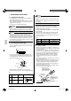
INSTALLATION MANUAL SPLIT SYSTEM Air Conditioners MODELS Ceiling-mounted Cassette type (Multi flow model) FCQ18PVJU FCQ24PVJU FCQ30PVJU English Français Read these instructions carefully before installation. Keep this manual in a handy place for future reference. This manual should be left with the equipment owner. Español Lire soigneusement ces instructions avant l’installation. Conserver ce manuel à portée de main pour référence ultérieure. Ce manuel doit être donné au propriétaire de l’équipement.
SPLIT SYSTEM Air Conditioners CONTENTS 1. 2. 3. 4. 5. 6. 7. 8. 9. 10. 11. 12. 13. 1. SAFETY CONSIDERATIONS ........................................... 1 BEFORE INSTALLATION .................................................. 2 SELECTING INSTALLATION SITE ................................... 3 PREPARATIONS BEFORE INSTALLATION ..................... 4 INSTALLATION PROCEDURES FOR FRESH AIR INTAKE DUCT CONNECTION.......................................... 5 INDOOR UNIT INSTALLATION ..............................
• When wiring the power supply and connecting the remote controller wire and transmission wire, position the wires so that the control box lid can be securely fastened. Improper positioning of the control box lid may result in electric shocks, fire or the terminals overheating. • Before touching electrical parts, turn off the unit. • Do not touch the switch with wet fingers. Touching a switch with wet fingers can cause electric shock. • Be sure to install an earth leakage breaker.
• This unit, both indoor and outdoor, is suitable for installation in a commercial and light industrial environment. If installed as a household appliance it could cause electromagnetic interference. Table 2 Remote controller Wired type Wireless type BRC1C71 BRC7C812 WARNING • Entrust installation to the place of purchase or a qualified person. Improper installation could lead to leak and, in worse cases, electric shock of fire.
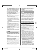
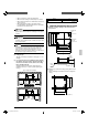
• If the supporting structural members are not strong enough to take the unit’s weight, the unit could fall out of place and cause serious injury. PREPARATIONS BEFORE INSTALLATION Refrigerant pipe 30 11/16 (Suspension bolt pitch) WARNING 4. (1) Relation of ceiling opening to unit and suspension bolt position 33 1/16 (Indoor unit) • Do not install unit in an area where flammable materials are present due to the risk explosion resulting in serious injury or death. H 11 3/4 or more (length: in.
Installation example ® 33 13/16 (Opening dimension inside the frame for ceiling) Ceiling slap 1 15/16 3 15/16 Anchor Long nut or turn-buckle Frame False ceiling Suspension bolt False ceiling NOTE) All the above parts are field supplied. 13/16 or more 33 13/16-*35 13/16 (Ceiling opening dimension) 13/16 or more (Ceiling-panel overlapping dimension) (length: in.) 5.
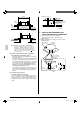
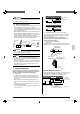
6-1 Insulation (field supply) Put the insulation tightly around the hole of the unit as shown. The ends of the side plate and the inner insulation must be completely adhered without leaving any clearance along the circumference of the hole. Inner insulation For new ceilings (2) • Refer to the paper pattern for installation (5) for ceiling opening dimension. Consult the builder or carpenter for details. • The center of the ceiling opening is indicated on the paper pattern for installation.
7. REFRIGERANT PIPING WORK 7-1 NOTE GENERAL INSTRUCTIONS • For refrigerant pipe of outdoor units, see the installation manual attached to the outdoor unit. • Before refrigerant piping work, check which type of refrigerant is used. Proper operation is not possible if the types of refrigerant are not the same. • The outdoor unit is charged with refrigerant. DANGER • Refrigerant gas may produce toxic gas if it comes in contact with fire such as from a fan heater, stove or cooking device.
CAUTION 1/100 gradient or more 3.28 - 4.92ft. • Be sure to insulate any field piping all the way to the piping connection inside the unit. Any exposed pipe may cause condensate or burns if touched. 7-4 Brazing refrigerant piping • Before brazing local refrigerant pipe, nitrogen gas shall be blown through the pipe to expel air from the pipe. If your brazing is done without nitrogen gas blowing, a large amount of oxide film develops inside the pipe, and could cause system malfunction.
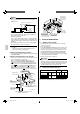
Power supply terminal block NOTE • The incline of attached drain hose (1) should be 2 15/16 in. or less so that the drain socket does not have to stand additional force. 2 15/16 or less 29 1/2 or less Drain hose (1) (accessory) (length: in.) Select converging drain pipe whose gauge is suitable for the operating capacity of the unit. • Drain pipe connections Do not connect the drain pipe directly to sewage pipes that smell of ammonia.
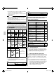
9-3 SPECIFICATIONS FOR FIELD SUPPLIED FUSES AND WIRES Power supply wiring Field fuses Size Model FCQ18PVJU FCQ24PVJU FCQ30PVJU 15A Clamp A Transmission wiring Wire Size Wire size must comply Sheathed wire with local (2 wires) codes. P1 P2 10.
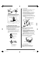
1. When using 1 remote controller for 1 indoor unit. (Normal operation) Connect wires of the same gauge to both sides. Power Supply 208-230V ~ Outdoor unit Control box 60Hz IN/D OUT/D F1 F2 F1 F2 L1 L2 2. Tightening torque for the terminal screws. • Use the correct screwdriver for tightening the terminal screws. If the blade of screwdriver is too small, the head of the screw might be damaged, and the screw will not be properly tightened.
(2) Turn the MAIN/SUB changeover switch on one of the two remote controllers PC boards to “S”. (Leave the switch of the other remote controller set to “M”.) (Factory setting) S M Remote controller PC board Only one remote controller needs to be changed if factory settings have remained untouched. S M 11. FIELD SETTING Make sure the control box lids are closed on the indoor and outdoor units. Field setting must be made from the remote controller in accordance with the installation condition.
13. TEST OPERATION Refer to the section of “FOR THE FOLLOWING ITEMS, TAKE SPECIAL CARE DURING CONSTRUCTION AND CHECK AFTER INSTALLATION IS FINISHED.” on page 3. • Make sure if the service lids are closed on the indoor and outdoor units. • After finishing the construction of refrigerant pipe, drain pipe and electric wire, conduct the check operation referring to the installation manual of the outdoor unit. • The operation lamp of the remote controller will flash when a malfunction occurs.
E5 E7 E9 F3 F6 H9 J3 J5 J6 J9 JA JC L4 L5 L8 L9 LC P1 P3 P4 PJ U0 U2 U3 U4 UF U9 UA English 01_EN_3PN06240-13M.indd 14 Compressor motor lock malfunction Outdoor fan motor lock malfunction Outdoor fan instantaneous overcurrent malfunction Electronic expansion valve faulty (outdoor unit) Discharge pipe temperature abnormal (outdoor unit) The refrigerant is overcharged.
3PN06240-13M EM08A095 00_CV_3PN06240-13M.