
Service manual


ESIEN05-04 Disassembly and Maintenance
Part 5 – Disassembly and Maintenance 5–83
3
5
1
5
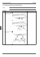
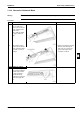
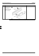
3 Pull down the control box
and let it hang by the 2
locations in the rear.
Electrical parts can now
be removed.
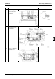
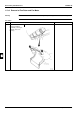
4 Disconnect the
connector mounted on
the PC board.
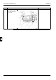
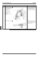
5 Remove the PC board
installation screw.
Step Procedure Points