
Service manual

Disassembly and Maintenance ESIEN05-04
5–70 Part 5 – Disassembly and Maintenance
3
1
55
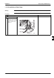
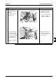
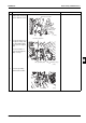
9 Install the drain pan
putting the lead wire of
float switch and drain
pump into the wire
groove securely.
When install the drain
pan, put the lead wires in
wiring groove and pass
the lead wires above the
black sealing material on
the drain pan securely.
(Otherwise, due dripping
may occur due to leakage
of cool air.)
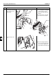
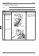
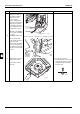
10 Installing the bell mouth.
When install the bell
mouth, put the lead wires
of fan motor and
thermistor into the wiring
groove securely as they
were, taking care that the
wires do not contact with
fan rotor.
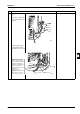
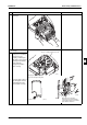
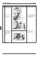
11 Tighten the two screws to
install the bell mouth.
(Bell mouth is formed
with step.)
Q A convex protrusion is
provided at the position of bell
mouth fixing screw to prevent
misjudgment with switch box
fixing position.
Step Procedure Points
Wiring groove
(S2685)
Wiring groove
Fan motor lead wire
Thermistor ass'y wire
(S2686)
(S2653)
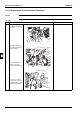
(S2654)