
Service manual

ESIEN05-04 Disassembly and Maintenance
Part 5 – Disassembly and Maintenance 5–21
3
5
1
5
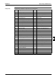
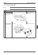
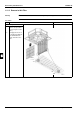
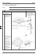
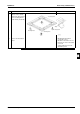
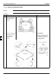
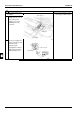
Components The table below contains the components of the exploded view.
No. Component No. Component
1 Top plate assy 7.5 Flare nut 5/8
2 Suction plate assy 8 Drain pan sealing assy
3 Air filter 9 Drain pan fixing
4 Fan assy 10 Discharge plate assy
4.1 Fan top plate assy 11 Bottom assy
4.2 Fan housing bottom (small) 12 Filter holding plate
4.3 Fan housing top (small) 13 Hook
4.4.1 Rotor assy 14 Pipe support plate
4.4.2 Rotor assy 15 Pipe sealing
4.4.2 Rotor assy 16 Switch box assy
4.5 Fan motor assy 16.1 Switch box cover assy
4.6 Fan motor stand 16.2 Switch box mounting plate assy
4.7 Motor fixing plate assy 16.3 Resin case
4.8 Capacitor 5 microf 16.4 PCB assy
4.9 Cable holder 16.5 Transformer
4.10 Bearing board 16.6 Terminal board
4.11 Vibro proof rubber assy 16.7 Terminal strip
4.12 Bearing fixing plate 16.8 Tie wrap with clip (l=140)
4.13 Shaft assy 16.9 Wire harness (X2M - X27A)
4.14 Cuppling 16.10 Wire harness (X1M - X5A)
4.15 Hexagon socket screw 16.11 Blind rubber butching
5 Right side plate assy 16.12 Thermistor (air)
6 Left side plate assy 16.13 Thermistor (liquid)
7 Heat exchanger assy 17
7.1 Distributor with filter 18
7.2 Single union joint 3/8 19
7.3 Flare nut 3/8 20
7.4 Single union joint 5/8