
Service manual


ESIEN05-04 Disassembly and Maintenance
Part 5 – Disassembly and Maintenance 5–17
3
5
1
5
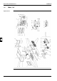
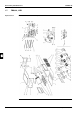
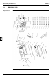
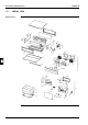
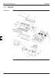
Components The table below contains the components of the exploded view.
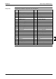
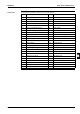
No. Component No. Component
1 Top plate assy 6.22 Thermistor
2 Fan assy + fan mounting plate 6.23 Tie wrap with clip
3 Side plate right 6.24 PCB assy
4 Side plate left 6.25 Power supply transformer
5 Service cover assy 6.26 Earth wire
6 Switch box assy 6.27 Insulation switch box
6.1 Switch box fixing plate 6.28 Insulation switch box
6.3 Terminal fixing plate 6.29 Insulation switch box
6.4 Magnetic contacor 7 Hook
6.6 Switch box body 8 Filter cover
6.7 Option fixing plate left 9 Fixture heat exchanger right
6.8 Option fixing plate right 10 Fixture heat exchanger left
6.9 Wire harness 11 By-pass sealing plate
6.10 Wire harness 12 Heat exchanger lassy
6.14 Wire harness 13 Drain pan assy
6.15 Wire harness 14 Bottom plate assy
6.16 Wire harness 15 Airfilter
6.17 Wire harness 16 Pipe fixing plate
6.18 PCB assy 17 Clamp
6.19 Locking guard spacer 18 Clamp
6.20 Terminal strip 19 Thermistor fixing
6.21 Thermistor