
Service manual


ESIEN05-04 Disassembly and Maintenance
Part 5 – Disassembly and Maintenance 5–15
3
5
1
5
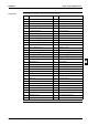
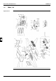
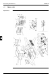
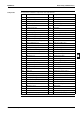
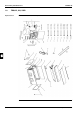
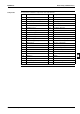
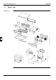
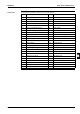
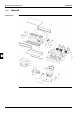
Components The table below contains the components of the exploded view.
No. Component No. Component
1 Top plate assy 31 Fan assy
2 Right plate assy 31.1 Fan top plate
3 Left plate assy 31.2 Fan housing bottom
4 Interchangeable plate 31.3 Fan housing top
5 Small bottom plate 31.4 Rotor assy
6 Large bottom plate 31.5 Fan motor
7 Air outlet flange 31.6 Fan motor stand
8 Center stay assy 31.7 Motor fixing plate assy
9 Air filter holding plate assy 31.8 Rotor assy
10 Stay for fan top panel assy 31.8.1 Hexagon socket screw
11 Fan side blind plate assy 31.9 Shaft assy
12 Cooler side blind plate assy 31.10 Coupling
13 Pipe setting plate assy 31.11 Vibro proof rubber assy
14 Swtich box cover assy 31.12 Bearing board
15 Drain pan setting plate 31.13 Bearing fixing plate
16 Drain socket cover assy 1 32 Switch box assy
17 Drain socket cover assy 2 32.1 Switch box body
18 Hanger bracket 32.2 Switch box fixing plate
19 Drain pan assy 32.3 Terminal fixing plate
19.1 Drain socket cap 32.4 Option fixing plate left
20 Heat exchanger assy 32.5 Option fixing plate right
20.1 Distributor with filter assy 32.6 PCB assy
20.2 Single union joint 32.7 Air thermistor
20.3 Single union joint 32.8 Power supply transformer
20.4 Flare nut 32.9 Fan motor capacitor
20.5 Flare nut 32.10 Terminal for remote control
21 Air filter assy 32.11 Terminal for power supply
22 Service cover assy 32.12 Wire harness
23 Drain pump fixing plate 32.13 Wire harness
24 Service cover cap assy 32.14 Tie wrap with clip
25 Drain pump 33 Thermistor (liquid)
26 Float switch 35 Thermistor fixing blade
27 Drain hose assy 36 Metal clamp
28 Vibration absorber 37 Drain hose
29 Plain washer 38 Insulation for joint (gas)
30 Fitting bolt drain pump 39 Insulation for joint (liquid)