
Service manual

ESIEN05-04 Disassembly and Maintenance
Part 5 – Disassembly and Maintenance 5–9
3
5
1
5
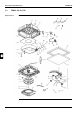
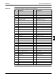
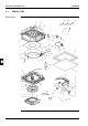
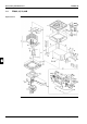
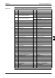
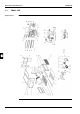
Components The table below contains the components of the exploded view.
No. Component No. Component
B1 Heat exchanger assy E21 Lock metal
B1-1 Header assy E22 Single phase AC fan motor
B1-1-1 Single union joint 3/8
(Only for FFQ25 and FFQ35)
E23 Vibro-isolating bolt
E24 Vibration isolator
B1-1-1 Single union joint 1/2
(Only for FFQ50 and FFQ60)
E25 Drain pump ASSY
E25-1 Drain pump
B1-2 Liquid pipe assy E25-2 Drain pump mounting plate
B1-2-1 Distributor E25-3 Mounting bolt
B1-2-2 Single union joint 1/4 E25-4 Rubber vibration isolator
B3 Flare nut E26 Float switch mounting plate assy
B4 Flare nut E26-1 Float switch mounting plate
C1 Turbo fan rotor E26-2 Float switch assy
C2 Fan rotation stopper F1 Top plate assy
C3 Insulation nut F2 Front plate sealing assy
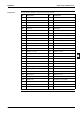
E1 Electric components assy F3 Localized die rear plate
E2 Switch box assy F4 Localized die rear plate
E3 Cover, switch box F5 Localized die rear plate
E4 Power transformer F6 Hanger metal assy
E5 Printed circuit assy F7 Blind plate assy
E5-1 Capacity setting adapter F7-1 Grounding wire
E6 Housing, printed circuit F7-2 Grounding screw
E7 Capacitor, fan Motor F7-3 Locking wire saddle
E8 Terminal block F8 H/E mounting plate
E9 Terminal block F9 Hold Plate assy
E10 Wire harness (transmission) F10 Bell mouth assy
E10-1 Fuse holder F11 Inner insulation top panel
E10-2 Fuse F12 Drain pan top assy
E11 Wire harness assy F12-1 Drain plug
E12 Wire harness assy (swing motor) F13 Thermistor mounting spring
E13 Relay harness for fan motor F14 Bushing
E14 Thermistor (for air) G1 Drain hose assy
E15 Thermistor assy K1 Internal drain hose
E15-1 Thermistor K2 Hose band
E16 Grounding screw K3 Insulation for joint (liquid)
E17 Grounding wire K4 Insulation for joint (gas)
E18 Grounding wire K6 Drain hose sealing material
E19 Wire clip K7 sealing material
E20 Wire clip